ASRock X570 Phantom Gaming 4 Quick Installation Guide
ASRock X570 Phantom Gaming 4 Manual
 |
View all ASRock X570 Phantom Gaming 4 manuals
Add to My Manuals
Save this manual to your list of manuals |
ASRock X570 Phantom Gaming 4 manual content summary:
- ASRock X570 Phantom Gaming 4 | Quick Installation Guide - Page 1
documentation are furnished for informational use only and subject to change without notice, and should not be constructed as a commitment by ASRock. ASRock assumes no responsibility for any errors or omissions that may appear in this documentation. With respect to the contents of this documentation - ASRock X570 Phantom Gaming 4 | Quick Installation Guide - Page 2
if the goods fail to be of acceptable quality and the failure does not amount to a major failure. If you require assistance please call ASRock Tel : +886-2-28965588 ext.123 (Standard International call charges apply) The terms HDMI® and HDMI High-Definition Multimedia Interface, and the HDMI logo - ASRock X570 Phantom Gaming 4 | Quick Installation Guide - Page 3
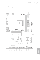
: MIC IN USB 3.2 Gen1 Top: T: USB5 RJ-45 B: USB6 CHA_FAN3/WP SPI_TPM_J1 X570 PHANTOM GAMING 4 1 PCIE1 1 USB_1 USB3_7_8 1 CHA_FAN1/WP M2_2 M2_1 SATA3_5_6 SATA3_7_8 RoHS PCIE2 1 TB1 PCIE3 CMOS Battery AMD Premium X570 SATA3_1_2 M2_3 PCIE4 HD_AUDIO1 1 1 TPMS1 COM1 1 1 RGB_LED1 - ASRock X570 Phantom Gaming 4 | Quick Installation Guide - Page 4
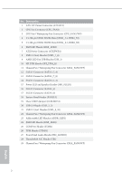
Fan / Waterpump Fan Connector (CPU_FAN2/WP) 4 2 x 288-pin DDR4 DIMM Slots (DDR4_A1, DDR4_B1) 5 2 x 288-pin DDR4 DIMM Slots (DDR4_A2, DDR4_B2) 6 RGB LED Header (RGB_LED2) 7 ATX Power Connector (ATXPWR1) 8 USB 3.2 Gen1 Header (USB3_7_8) 9 AMD LED Fan USB Header (USB_1) 10 SPI TPM Header (SPI_TPM_J1 - ASRock X570 Phantom Gaming 4 | Quick Installation Guide - Page 5
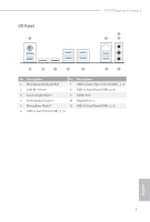
I/O Panel 1 X570 Phantom Gaming 4 3 2 4 11 10 9 8 7 6 5 No. Description 1 PS/2 Mouse/Keyboard Port 2 LAN RJ-45 Port* 3 Line In (Light Blue)** 4 Front Speaker (Lime)** 5 Microphone (Pink)** 6 USB 3.2 Gen1 Ports (USB3_5_6) No. Description 7 USB 3.2 Gen2 Type-A Port (USB31_1_2) 8 USB 3.2 - ASRock X570 Phantom Gaming 4 | Quick Installation Guide - Page 6
Speed LED Status Off Orange Green Description 10Mbps connection 100Mbps connection 1Gbps connection ** Function of the Audio Ports in 7.1-channel Configuration: Port Light Blue (Rear panel) Lime (Rear panel) Pink (Rear panel) Lime (Front panel) Function Rear Speaker Out Front Speaker Out Central - ASRock X570 Phantom Gaming 4 | Quick Installation Guide - Page 7
VGA cards and CPU support list on ASRock's website as well. ASRock website http://www.asrock.com. 1.1 Package Contents • ASRock X570 Phantom Gaming 4 Motherboard (ATX Form Factor) • ASRock X570 Phantom Gaming 4 Quick Installation Guide • ASRock X570 Phantom Gaming 4 Support CD • 2 x Serial ATA (SATA - ASRock X570 Phantom Gaming 4 | Quick Installation Guide - Page 8
Capacitor design • 2oz Copper PCB • Supports AMD AM4 socket RyzenTM 2000 and 3000 series processors • Digi Power design • 10 Power Phase design Chipset • AMD X570 Memory • Dual Channel DDR4 Memory Technology • 4 x DDR4 DIMM Slots • AMD Ryzen series CPUs (Matisse) support DDR4 4066+ (OC)/3466(OC - ASRock X570 Phantom Gaming 4 | Quick Installation Guide - Page 9
X570 Phantom Gaming 4 Graphics AMD Ryzen series CPUs (Pinnacle Ridge) • 2 x PCI Express 3.0 x16 Slots (PCIE1/PCIE3: single at x16 (PCIE1); dual at x16 (PCIE1) / x4 (PCIE3))* AMD Ryzen series CPUs (Picasso) • 2 x PCI Express 3.0 x16 Slots (PCIE1/PCIE3: single at x8 (PCIE1); dual at x8 (PCIE1) / x4 - ASRock X570 Phantom Gaming 4 | Quick Installation Guide - Page 10
Supports Wake-On-LAN • Supports Lightning/ESD Protection • Supports Energy Efficient Ethernet 802.3az • Supports 10 Gb/s) (Supports ESD Protection) • 6 x USB 3.2 Gen1 Ports (Supports ESD Protection) • 1 x RJ-45 LAN Port with • 1 x Hyper M.2 Socket (M2_3), supports M Key type 2230/2242/2260/2280/22110 - ASRock X570 Phantom Gaming 4 | Quick Installation Guide - Page 11
X570 Phantom Gaming 4 Connector • 1 x COM Port Header • 1 x TPM Header • 1 x SPI TPM Header • 1 x Power LED and Speaker Header • 2 x RGB LED Headers * Support in total up to 12V/3A, 36W LED Strip • 1 x Addressable LED Header * Supports in total up to 5V/3A, 15W LED Strip • 1 x CPU Fan Connector - ASRock X570 Phantom Gaming 4 | Quick Installation Guide - Page 12
detailed product information, please visit our website: http://www.asrock.com Please realize that there is a certain risk involved with overclocking, including adjusting the setting in the BIOS, applying Untied Overclocking Technology, or using third-party overclocking - ASRock X570 Phantom Gaming 4 | Quick Installation Guide - Page 13
X570 Phantom Gaming 4 Chapter 2 Installation This is an ATX form factor motherboard. Before you install the motherboard, study the configuration of your chassis to ensure that the motherboard fits into it. Pre-installation Precautions Take note of the following precautions before you install - ASRock X570 Phantom Gaming 4 | Quick Installation Guide - Page 14
2.1 Installing the CPU Unplug all power cables before installing the CPU. 1 2 12 English - ASRock X570 Phantom Gaming 4 | Quick Installation Guide - Page 15
X570 Phantom Gaming 4 3 13 English - ASRock X570 Phantom Gaming 4 | Quick Installation Guide - Page 16
the CPU into this motherboard, it is necessary to install a larger heatsink and cooling fan to dissipate heat. You also need to spray thermal grease between other. Please turn off the power or remove the power cord before changing a CPU or heatsink. Installing the CPU Box Cooler SR1 1 2 14 English - ASRock X570 Phantom Gaming 4 | Quick Installation Guide - Page 17
X570 Phantom Gaming 4 3 4 CPU_FAN1 15 English - ASRock X570 Phantom Gaming 4 | Quick Installation Guide - Page 18
Installing the AM4 Box Cooler SR2 1 2 16 English - ASRock X570 Phantom Gaming 4 | Quick Installation Guide - Page 19
X570 Phantom Gaming 4 3 17 English - ASRock X570 Phantom Gaming 4 | Quick Installation Guide - Page 20
4 CPU_FAN1 18 English - ASRock X570 Phantom Gaming 4 | Quick Installation Guide - Page 21
Installing the AM4 Box Cooler SR3 1 X570 Phantom Gaming 4 2 19 English - ASRock X570 Phantom Gaming 4 | Quick Installation Guide - Page 22
3 4 20 English - ASRock X570 Phantom Gaming 4 | Quick Installation Guide - Page 23
X570 Phantom Gaming 4 5 4-pin FAN cable CPU_FAN1 6 CPU_FAN1 USB_5 Please note that this connector is the interface to the LED control board on the SR3, it requires the AMD utility "SR3 Settings Software" to control the LED. *The diagrams shown here are for reference only. The headers might be - ASRock X570 Phantom Gaming 4 | Quick Installation Guide - Page 24
and DIMM may be damaged. 4. We suggest that you install the memory modules on DDR4_A2 and DDR4_B2 first for better DRAM compatibility on 2 DIMMs configuration. AMD non-XMP Memory Frequency Support Ryzen Series CPUs (Matisse): UDIMM Memory Slot A1 A2 B1 B2 Frequency (Mhz) - SR - - 3200 - ASRock X570 Phantom Gaming 4 | Quick Installation Guide - Page 25
Ryzen Series CPUs (Picasso): UDIMM/SO-DIMMs Memory Slot # of DIMMs on # of Ranks the Channel per DIMM 1.20V 1 of 1 1 of 2 SR: 2933 xR DR: 2677 SR: 2667 xR-0 rank DIMM, 1Rx4 or 1Rx8 on DIMM module label DR: Dual rank DIMM, 2Rx4 or 2Rx8 on DIMM module label X570 Phantom Gaming 4 English 23 - ASRock X570 Phantom Gaming 4 | Quick Installation Guide - Page 26
The DIMM only fits in one correct orientation. It will cause permanent damage to the motherboard and the DIMM if you force the DIMM into the slot at incorrect orientation. 1 2 3 24 English - ASRock X570 Phantom Gaming 4 | Quick Installation Guide - Page 27
X570 Phantom Gaming 4 2.4 Expansion Slots (PCI Express Slots) There are 4 PCI Express slots on the motherboard. Before installing an expansion card, please make sure that the power supply is switched off or the power cord is unplugged. Please read the documentation of the - ASRock X570 Phantom Gaming 4 | Quick Installation Guide - Page 28
CLRCMOS1 for 3 seconds. Please remember to remove the jumper cap after clearing the CMOS. If you need to clear the CMOS when you just finish updating the BIOS, you must boot up the system first, and then shut it down before you do the clear-CMOS action. English 26 - ASRock X570 Phantom Gaming 4 | Quick Installation Guide - Page 29
X570 Phantom Gaming 4 2.6 Onboard Headers and Connectors Onboard headers and connectors are NOT jumpers. Do NOT place jumper caps over these headers and connectors. Placing jumper caps over - ASRock X570 Phantom Gaming 4 | Quick Installation Guide - Page 30
p.1, No. 16) SATA3_2 SATA3_8 SATA3_6 SATA3_1 SATA3_7 SATA3_5 SATA3_3 SATA3_4 These eight SATA3 connectors support SATA data cables for internal storage devices with up to 6.0 Gb/s data transfer rate. AMD LED Fan USB Header (4-pin USB_1) (see p.1, No. 9) 1 GND P- P+ USB_PWR This header is used - ASRock X570 Phantom Gaming 4 | Quick Installation Guide - Page 31
X570 Phantom Gaming 4 Front Panel Audio Header (9-pin HD_AUDIO1) (see p.1, No. 27) GND PRESENCE# MIC_RET OUT_RET 1 OUT2_L J_SENSE OUT2_R MIC2_R MIC2_L This header is for connecting audio devices to the front audio panel. 1. High Definition Audio supports Jack Sensing, but the panel wire on the - ASRock X570 Phantom Gaming 4 | Quick Installation Guide - Page 32
No. 26) 1 PCICLK FRAME PCIRST# LAD3 +3V LAD0 +3VSB GND GND SMB_CLK_MAIN SMB_DATA_MAIN LAD2 LAD1 GND S_PWRDWN# SERIRQ# GND This connector supports Trusted Platform Module (TPM) system, which can securely store keys, digital certificates, passwords, and data. A TPM system also helps enhance network - ASRock X570 Phantom Gaming 4 | Quick Installation Guide - Page 33
X570 Phantom Gaming SPI_DQ2 This connector supports SPI Trusted Platform slot). * For the further information, please visit www.asrock.com. 1 12V G R B RGB header is used to connect RGB LED extension cable which allows users to choose from various LED lighting effects. Caution: Never install - ASRock X570 Phantom Gaming 4 | Quick Installation Guide - Page 34
LED extension cable which allows users to choose from various LED lighting effects. Caution: Never install the Addressable LED cable in the wrong orientation; otherwise, the cable may be damaged. * Please refer to page 43 for further instructions on this header. Serial Port Header (9-pin COM1) (see - ASRock X570 Phantom Gaming 4 | Quick Installation Guide - Page 35
X570 Phantom Gaming 4 2.7 Post Status Checker Post Status Checker (PSC) diagnoses the computer when users power on the machine. It emits a red light to indicate whether the CPU, memory, VGA or storage is dysfunctional. The lights go off if the four mentioned above are functioning normally. 33 - ASRock X570 Phantom Gaming 4 | Quick Installation Guide - Page 36
2.8 M.2_SSD (NGFF) Module Installation Guide (M2_1) The M.2, also known as the Next Generation Form Factor (NGFF), is a small size and versatile card edge connector that aims to replace mPCIe and mSATA. The M.2 Socket (M2_1) supports M Key type 2230/2242/2260/2280/22110 M.2 PCI Express module up to - ASRock X570 Phantom Gaming 4 | Quick Installation Guide - Page 37
D C B A E D C B A E D C B A X570 Phantom Gaming 4 Step 3 Move the standoff based on the module type and length. the motherboard. Step 5 Gently insert the M.2 (NGFF) SSD module into the M.2 slot. Please be aware that the M.2 (NGFF) SSD module only fits in one orientation. E D C B - ASRock X570 Phantom Gaming 4 | Quick Installation Guide - Page 38
-SD6PP4M-128G( Gen2 x2) INTEL 6000P-SSDPEKKF256G7 (nvme) INTEL 6000P-SSDPEKKF512G7 (nvme) Kingston SHPM2280P2 / 240G (Gen2 x4) Samsung XP941-MZHPU512HCGL(Gen2x4) For the latest updates of M.2_SSD (NFGG) module support list, please visit our website for details: http://www.asrock.com English 36 - ASRock X570 Phantom Gaming 4 | Quick Installation Guide - Page 39
X570 Phantom Gaming 4 2.9 M.2 WiFi/BT Module Installation Guide (M2_2) The M.2, also known as the Next Generation Form Factor (NGFF), is a small size and versatile card edge connector that aims to replace mPCIe and mSATA. The M.2 Socket (Key E) supports type 2230 WiFi/BT module. * The M.2 socket - ASRock X570 Phantom Gaming 4 | Quick Installation Guide - Page 40
A A 20o A Step 3 Gently insert the WiFi/BT module into the M.2 slot. Please be aware that the module only fits in one orientation. Step 4 Tighten the screw with a screwdriver to secure the module into place. Please do not overtighten the screw as this might damage the module. English 38 - ASRock X570 Phantom Gaming 4 | Quick Installation Guide - Page 41
X570 Phantom Gaming 4 2.10 M.2_SSD (NGFF) Module Installation Guide (M2_3) The M.2, also known as the Next Generation Form Factor (NGFF), is a small size and versatile card edge connector that aims to replace mPCIe and mSATA. The M.2 Socket (M2_3) supports M Key type 2230/2242/2260/2280/22110 M.2 - ASRock X570 Phantom Gaming 4 | Quick Installation Guide - Page 42
nut to be used. Hand tighten the standoff into the desired nut location on the motherboard. Step 5 Gently insert the M.2 (NGFF) SSD module into the M.2 slot. Please be aware that the M.2 (NGFF) SSD module only fits in one orientation. E D C B A 20o English 40 - ASRock X570 Phantom Gaming 4 | Quick Installation Guide - Page 43
E D NUT2 NUT1 X570 Phantom Gaming 4 Step 6 Tighten the screw with a screwdriver to secure the module into place. Please do not overtighten the screw as this might damage the module. M.2_SSD (NGFF) Module Support List Vendor SanDisk Intel Intel Kingston Samsung ADATA Crucial ezlink Intel - ASRock X570 Phantom Gaming 4 | Quick Installation Guide - Page 44
. Connecting the LED Strip Connect your RGB LED strip to the RGB LED Header (RGB_LED1) on the motherboard. X570 PHANTOM GAMING 4 1 B 12V G R RGB_LED2 1 12V G R B RGB_LED1 1 12V G R B 1. Never install the RGB LED cable in the wrong orientation; otherwise, the cable may be damaged. 2. Before - ASRock X570 Phantom Gaming 4 | Quick Installation Guide - Page 45
the Addressable RGB LED Strip Connect your Addressable RGB LED strip to the Addressable LED Header (ADDR_LED1) on the motherboard. ADDR_LED1 1 GND DO_ADDR VOUT X570 PHANTOM GAMING 4 1 1. Never install the RGB LED cable in the wrong orientation; otherwise, the cable may be damaged. 2. Before - ASRock X570 Phantom Gaming 4 | Quick Installation Guide - Page 46
. Download this utility from the ASRock Live Update & APP Shop and start coloring your PC style your way! Drag the tab to customize your preference. Toggle on/off the RGB LED switch Sync RGB LED effects for all LED regions of the motherboard Select a RGB LED light effect from the drop-down menu - ASRock X570 Phantom Gaming 4 | Quick Installation Guide - Page 47
• ASRock X570 Phantom Gaming 4-Motherboard (ATX-Formfaktor) • ASRock X570 Phantom Gaming 4-Schnellinstallationsanleitung • ASRock X570 Phantom Gaming 4-Support-CD • 2 x Serial-ATA- (SATA) Datenkabel (optional) • 3 x Schrauben für M.2-Sockel (optional) • 1 x E/A-Blendenabschirmung 45 Deutsch - ASRock X570 Phantom Gaming 4 | Quick Installation Guide - Page 48
ützt AMD-AM4-Sockel für Prozessoren der Serie RyzenTM 2000 und 3000 • Digi Power design • 10-Leistungsphasendesign • AMD X570 • Dualkanal Weitere Informationen finden Sie in der Speicherkompatibilitätsliste auf der ASRock-Webseite. (http://www.asrock.com/) * Bitte beachten Sie Seite 22 für die - ASRock X570 Phantom Gaming 4 | Quick Installation Guide - Page 49
X570 Phantom Gaming 4 Grafikkarte CPUs der AMD-Ryzen-Serie (Pinnacle Ridge) • 2 PCI Express 3.0 x16-Steckplätze (PCIE1/PCIE3:einzeln bei x16 (PCIE1); doppelt bei x16 (PCIE1) / x4 (PCIE3))* Prozessoren der AMD . Freigabespeicher von 16GB erfordert die Installation von 32GB Systemspeicher. • Dualer - ASRock X570 Phantom Gaming 4 | Quick Installation Guide - Page 50
6 x USB-3.2-Gen1-Ports (unterstützt Schutz gegen elektrostatische Entladung) • 1 x RJ-45-LAN-Port mit LED (Aktivität/Verbindung-LED und Geschwindigkeit-LED) • HD-Audioanschlüsse: Line /s) (mit Pinnacle Ridge und Picasso)* * Unterstützt NVMe-SSD als Bootplatte * Unterstützt ASRock U.2-Kit Deutsch 48 - ASRock X570 Phantom Gaming 4 | Quick Installation Guide - Page 51
X570 Phantom Gaming 4 Anschluss BIOSFunktion • 1 x COM-Anschluss-Stiftleiste • 1 x TPM-Stiftleiste • 1 x SPI-TPM-Stiftleiste • an Frontblende • 1 x AMD-LED-Lüfter-USB-Stiftleiste • 1 x Thunderbolt Erweiterungskartenanschluss (5-polig) (Unterstützt nur ASRock Thunderbolt AIC-Karten) • 1 - ASRock X570 Phantom Gaming 4 | Quick Installation Guide - Page 52
Netzteil erforderlich) * Detaillierte Produktinformationen finden Sie auf unserer Webseite: http://www.asrock.com Bitte beachten Sie, dass mit einer Übertaktung, zu der die Anpassung von BIOS-Einstellungen, die Anwendung der Untied Overclocking Technology oder die Nutzung von Übertaktungswerkzeugen - ASRock X570 Phantom Gaming 4 | Quick Installation Guide - Page 53
X570 Phantom Gaming 4 1.3 Jumpereinstellung Die Abbildung zeigt, wie die Jumper eingestellt werden. Wenn die nach der CMOS-Löschung zu entfernen. Falls Sie den CMOS direkt nach Abschluss der BIOS-Aktualisierung löschen müssen, starten Sie das System zunächst; fahren Sie es dann vor der CMOS - ASRock X570 Phantom Gaming 4 | Quick Installation Guide - Page 54
1.4 Integrierte Stiftleisten und Anschlüsse Integrierte Stiftleisten und Anschlüsse sind KEINE Jumper. Bringen Sie KEINE Jumper-Kappen an diesen Stiftleisten und Anschlüssen an. Durch Anbringen von Jumper-Kappen an diesen Stiftleisten und Anschlüssen können Sie das Motherboard dauerhaft beschädigen. - ASRock X570 Phantom Gaming 4 | Quick Installation Guide - Page 55
X570 Phantom Gaming 4 Serial-ATA-IIIAnschlüsse (SATA3_5_6: siehe S. 1, Nr. 12) (SATA3_7_8: siehe S. 1, Nr. 13) (SATA3_1_2: für interne Speichergeräte mit einer Datenübertragungsg eschwindigkeit bis 6,0 Gb/s. SATA3_3 SATA3_4 AMD-LED-Lüfter-USBStiftleiste (4-polig, USB_1) (siehe S. 1, Nr. 9) USB - ASRock X570 Phantom Gaming 4 | Quick Installation Guide - Page 56
Audiostiftleiste (Frontblende) (9-polig, HD_AUDIO1) (siehe S. 1, Nr. 27) GND PRESENCE# MIC_RET OUT_RET 1 OUT2_L J_SENSE OUT2_R MIC2_R MIC2_L Diese Stiftleiste dient dem Anschließen von Audiogeräten an der Frontblende. 1. High Definition Audio unterstützt Anschlusserkennung, der Draht am Gehäuse - ASRock X570 Phantom Gaming 4 | Quick Installation Guide - Page 57
X570 Phantom Gaming 4 CPU-WasserpumpenLüfteranschluss (4-polig, CPU_FAN2/WP) (siehe S. 1, Nr. 3) FAN_SPEED_CONTROL CPU_FAN_SPEED FAN_VOLTAGE GND 1 2 34 ATX-Netzanschluss (24-polig, ATXPWR1) (siehe S. 1, Nr. 7) 12 24 ATX-12-VNetzanschluss (8- - ASRock X570 Phantom Gaming 4 | Quick Installation Guide - Page 58
SPI-TPM-Stiftleiste (13-polig, SPI_TPM_J1) (siehe S. 1, Nr. 10) SPI_DQ3 +3.3V Dummy CLK SPI_MOSI RST# TPM_PIRQ 1 SPI_TPM_CS# GND RSMRST# SPI_MISO SPI_CS0 SPI_DQ2 ThunderboltErweiterungskartenanschluss (5-polig, TB1) (siehe S. 1, Nr. 28) RGB-LED-Stiftleisten (4-polig, RGB_LED1) (siehe S. 1, Nr. 24 - ASRock X570 Phantom Gaming 4 | Quick Installation Guide - Page 59
X570 Phantom Gaming 4 Adressierbare-LEDStiftleiste (3-polig, ADDR_LED1) (siehe S. 1, Nr. 23) Serieller-Port-Stiftleiste (9-polig, COM1) (siehe S. 1, Nr. 25) 1 GND DO_ADDR VOUT RRXD1 DDTR#1 DDSR#1 CCTS#1 1 RRI#1 RRTS#1 GND - ASRock X570 Phantom Gaming 4 | Quick Installation Guide - Page 60
sur le site Internet de ASRock. Site Internet ASRock http://www.asrock.com. 1.1 Contenu de l'emballage • Carte mère ASRock X570 Phantom Gaming 4 (facteur de forme ATX) • Guide d'installation rapide ASRock X570 Phantom Gaming 4 • CD d'assistance ASRock X570 Phantom Gaming 4 • 2 x câbles de données - ASRock X570 Phantom Gaming 4 | Quick Installation Guide - Page 61
X570 Phantom Gaming 4 1.2 Spécifications Plateforme Processeur Chipset • Facteur de forme ATX • Conception à condensateurs solides • PCB cuivre 2 onces • Prend en charge la gamme de processeurs AMD AM4 socket RyzenTM 2000 et 3000 • Digi Power design • Alimentation à 10 phases • AMD X570 Mémoire - ASRock X570 Phantom Gaming 4 | Quick Installation Guide - Page 62
Express 4.0 x1 • Prend en charge AMD Quad CrossFireXTM et CrossFireXTM • 1 x socket M.2 (Touche E), prend en charge les modules WiFi/BT type 2230 • Contact doré ée maximum de 16 Gb nécessite 32 Gb de mémoire système installée. • Double sortie graphique :Prend en charge les ports HDMI et DisplayPort - ASRock X570 Phantom Gaming 4 | Quick Installation Guide - Page 63
X570 Phantom Gaming 4 Audio • Audio 7.1 CH HD avec protection du 6 x ports USB 3.2 Gen1 (Protection contre les décharges électrostatiques) • 1 x port RJ-45 LAN avec LED (LED ACT/LIEN et LED VITESSE) • Connecteurs jack audio HD : Entrée ligne marrage * Prend en charge le kit ASRock U.2 61 Français - ASRock X570 Phantom Gaming 4 | Quick Installation Guide - Page 64
d'alimentation 12 V 8 broches • 1 x connecteur audio panneau frontal • 1 x embase USB de ventilateur LED AMD • 1 x connecteur Thunderbolt AIC (5 broches) (Prise en charge de la carte ASRock Thunderbolt AIC uniquement) • 1 x embase USB 2.0 (2 ports USB 2.0 pris en charge) (Protection contre les - ASRock X570 Phantom Gaming 4 | Quick Installation Guide - Page 65
X570 Phantom Gaming 4 Surveillance du matériel • Détection de température : Ventilateurs de CPU, CPU/pompe notre site : http://www.asrock.com Il est important de signaler que l'overclocking présente certains risques, incluant des modifications du BIOS, l'application d'une technologie d' - ASRock X570 Phantom Gaming 4 | Quick Installation Guide - Page 66
le capuchon du cavalier est installé sur les broches, le cavalier est « court-circuité ». Si le capuchon du cavalier n'est pas installé sur les broches, le données CMOS après une mise à jour du BIOS, vous devez tout d'abord redémarrer le système, puis l'éteindre avant de procéder à l'effacement - ASRock X570 Phantom Gaming 4 | Quick Installation Guide - Page 67
X570 Phantom Gaming 4 1.4 Embases et connecteurs de la carte mère Les embases et bouton de réinitialisation du panneau frontal du châssis. Appuyez sur le bouton de réinitialisation pour redémarrer l'ordinateur en cas de plantage ou de dysfonctionnement au démarrage. PLED (LED d'alimentation du - ASRock X570 Phantom Gaming 4 | Quick Installation Guide - Page 68
No. 20) 1 GND P- P+ USB_PWR USB_PWR PP+ GND DUMMY 1 GND P+ PUSB_PWR Cette embase sert à connecter le connecteur USB sur le dissipateur thermique AMD SR3. Cette carte mère comprend un connecteur. Cette embase USB 2.0 peut prendre en charge deux ports. Français Embases USB 3.2 Gen1 (USB3_7_8 à 19 - ASRock X570 Phantom Gaming 4 | Quick Installation Guide - Page 69
X570 Phantom Gaming 4 Embase audio du panneau frontal (HD_AUDIO1 à 9 broches) (voir p.1, No avec la HDA pour fonctionner correctement. Veuillez suivre les instructions figurant dans notre manuel et dans le manuel du châssis pour installer votre système. 2. Si vous utilisez un panneau audio - ASRock X570 Phantom Gaming 4 | Quick Installation Guide - Page 70
Connecteur pour ventilateur de pompe à eau du processeur (CPU_FAN2/WP à 4 broches) (voir p.1, No. 3) FAN_SPEED_CONTROL CPU_FAN_SPEED FAN_VOLTAGE GND 1 2 34 Cette carte mère est dotée d'un connecteur pour ventilateur de processeur à refroidissement par eau à 4 broches. Si vous envisagez de - ASRock X570 Phantom Gaming 4 | Quick Installation Guide - Page 71
X570 Phantom Gaming 4 Embase SPI TPM (SPI_TPM_J1 à 13 broches (AIC) Thunderbolt™ au connecteur AIC Thunderbolt via le câble GPIO. *Veuillez installer la carte Thunderbolt™ AIC sur PCIE3 (emplacement par défaut). Embase LED RVB 42 pour des instructions supplémentaires sur cette embase. Français 69 - ASRock X570 Phantom Gaming 4 | Quick Installation Guide - Page 72
jamais le câble LED adressable dans le mauvais sens. Dans le cas contraire, le câble peut être endommagé. *Veuillez consulter la page 43 pour des instructions supplémentaires sur cette embase. Cette embase COM1 prend en charge un module de port série. Français 70 - ASRock X570 Phantom Gaming 4 | Quick Installation Guide - Page 73
anche sul sito Web di ASRock. Sito Web di ASRock http://www.asrock.com. 1.1 Contenuto della confezione • Scheda madre ASRock X570 Phantom Gaming 4 (Form Factor ATX) • Guida rapida di installazione ASRock X570 Phantom Gaming 4 • CD di supporto ASRock X570 Phantom Gaming 4 • 2 x cavi dati Serial ATA - ASRock X570 Phantom Gaming 4 | Quick Installation Guide - Page 74
rame • Supporta processori socket AMD AM4 RyzenTM serie 2000 e 3000 • Digi Power design • Potenza a 10 fasi Chipset • AMD X570 Memoria • Tecnologia memoria riferimento all'elenco dei supporti di memoria sul sito di ASRock. (http://www.asrock.com/) * Fare riferimento a pagina 22 per il supporto - ASRock X570 Phantom Gaming 4 | Quick Installation Guide - Page 75
X570 Phantom Gaming 4 Grafica CPU serie AMD Ryzen (Pinnacle Ridge) • 2 alloggiamenti PCI Express 3.0 x16 (PCIE1/PCIE3:singolo a x16 (PCIE1); doppio a x16 (PCIE1) / x4 (PCIE3))* CPU serie AMD Ryzen (Picasso) • 2 alloggiamenti PCI Express 3.0 x16 (PCIE1/PCIE3:singolo a x8 (PCIE1); doppio a x8 (PCIE1 - ASRock X570 Phantom Gaming 4 | Quick Installation Guide - Page 76
• 6 x porte USB 3.2 Gen1 (supporto protezione da scariche elettrostatiche) • 1 x porta LAN RJ-45 con LED (ACT/LINK LED e SPEED LED) • Connettori audio HD: Ingresso linea / altoparlante frontale / Ridge e Picasso)* * Supporto di SSD NVMe come disco d'avvio * Supporta kit ASRock U.2 Italiano 74 - ASRock X570 Phantom Gaming 4 | Quick Installation Guide - Page 77
X570 Phantom Gaming 4 Connettore • 1 x connettore porta COM • 1 x connettore TPM x collettore USB AMD LED FAN • 1 x connettore Thunderbolt AIC (5-pin) (supporta solo carta ASRock Thunderbolt AIC) • da scariche elettrostatiche) Funzionalità BIOS • AMI UEFI Legal BIOS con interfaccia di supporto • - ASRock X570 Phantom Gaming 4 | Quick Installation Guide - Page 78
dettagliate sul prodotto, visitare il nostro sito Web: http://www.asrock.com Prestare attenzione al potenziale rischio previsto nella pratica di overclocking, inclusa la regolazione delle impostazioni nel BIOS, l'applicazione di tecnologia di Untied Overclocking o l'utilizzo - ASRock X570 Phantom Gaming 4 | Quick Installation Guide - Page 79
X570 Phantom Gaming 4 1.3 Impostazione jumper L'illustrazione mostra in che modo vengono impostati i jumper. Quando dopo aver azzerato la CMOS. Se è necessario azzerare la CMOS dopo l'aggiornamento del BIOS, è necessario riavviare prima il sistema e in seguito spegnerlo prima di eseguire l' - ASRock X570 Phantom Gaming 4 | Quick Installation Guide - Page 80
1.4 Header e connettori su scheda Gli header e i connettori sulla scheda NON sono jumper. NON posizionare cappucci del jumper su questi header e connettori. Il posizionamento di cappucci del jumper su header e connettori provocherà danni permanenti alla scheda madre. Header sul pannello del sistema - ASRock X570 Phantom Gaming 4 | Quick Installation Guide - Page 81
X570 Phantom Gaming 4 Connettori Serial ATA3 (SATA3_5_6: vedere pag. 1, n. 12) (SATA3_7_8: vedere pag. 1, n. 13) (SATA3_1_2: vedere pag.1, n. 14) (SATA3_3: vedere pag.1, n. 17) (SATA3_4: vedere pag.1, n. 16) Collettore USB AMD connettore USB sul dissipatore di calore AMD SR3. Su questa scheda madre - ASRock X570 Phantom Gaming 4 | Quick Installation Guide - Page 82
Jack sensing, ma il filo del pannello sullo chassis deve supportare HDA per funzionare correttamente. Seguire le istruzioni presenti nel nostro manuale e nel manuale dello chassis per installare il sistema. 2. Se si utilizza un pannello audio AC'97, installarlo sull'header audio del pannello - ASRock X570 Phantom Gaming 4 | Quick Installation Guide - Page 83
X570 Phantom Gaming 4 Connettore ventola pompa dell'acqua CPU (CPU_FAN2/WP a 4 pin) (vedere pag. 1, n. 3) FAN_SPEED_CONTROL CPU_FAN_SPEED FAN_VOLTAGE GND 1 2 34 Connettore di alimentazione ATX (ATXPWR1 a 24 pin) (vedere pag. 1, n. 7) - ASRock X570 Phantom Gaming 4 | Quick Installation Guide - Page 84
aggiuntiva Thunderbolt™ (AIC) al connettore Thunderbolt AIC utilizzando il cavo GPIO. * Installare la scheda AIC Thunderbolt™ su PCIE3 (slot predefinito). Collettore LED RGB (RGB_LED1 a 4 pin) (vedere pag. 1, n. 24) (RGB_LED2 a 4 pin) (vedere pag. 1, n. 6) 1 12V G R B Il collettore RGB viene - ASRock X570 Phantom Gaming 4 | Quick Installation Guide - Page 85
X570 Phantom Gaming 4 Header LED indirizzabile (ADDR_LED1 a 3 pin) (vedere pag. 1, n. 23) Header porta seriale (COM1 a 9 pin) (vedere pag. 1, n. 25) 1 GND DO_ADDR VOUT RRXD1 DDTR#1 DDSR#1 CCTS#1 1 RRI#1 RRTS#1 - ASRock X570 Phantom Gaming 4 | Quick Installation Guide - Page 86
X570 Phantom Gaming 4, una placa base fiable fabricada según el rigurosísimo control de calidad de ASRock. Ofrece un rendimiento excelente con un diseño resistente de acuerdo con el compromiso de calidad y resistencia de ASRock. Ya que las especificaciones de la placa base y el software de la BIOS - ASRock X570 Phantom Gaming 4 | Quick Installation Guide - Page 87
X570 Phantom Gaming 4 1.2 Especificaciones Plataforma CPU • Factor de forma ATX • Diseño de condensador sólido • Circuito impreso (PCB) de 2 oz de cobre • Admite los procesadores AM4 RyzenTM serie 2000 y 3000 con zócalo AMD en el sitio web de ASRock. (http://www.asrock.com/) * Consulte la pá - ASRock X570 Phantom Gaming 4 | Quick Installation Guide - Page 88
))* * Admite unidad de estado sólido de NVMe como disco de arranque • 2 x Ranuras PCI Express 4.0 x1 • Compatible con AMD Quad CrossFireXTM y CrossFireXTM • 1 x Zócalo M.2 (clave E), admite el tipo de módulo 2230 WiFi/BT • Contacto 15μGold en ranura VGA PCIe (PCIE1) • Tarjeta gráfica de la serie - ASRock X570 Phantom Gaming 4 | Quick Installation Guide - Page 89
X570 Phantom Gaming 4 LAN • Gigabit LAN 10/100/1000 Mb/s • Puertos USB 3.2 Gen1 (admite protección contra descargas electrostáticas) • 1 x Puerto LAN RJ-45 con LED (LED DE ACTIVIDAD/ENLACE y LED DE VELOCIDAD) • Conector de audio HD: Entrada de arranque * Admite el Kit U.2 de ASRock Español 87 - ASRock X570 Phantom Gaming 4 | Quick Installation Guide - Page 90
audio en el panel frontal • 1 x Base de conexiones USB de ventilador de LED AMD • 1 x conector Thunderbolt AIC (5 contactos) (Solamente se admite tarjeta AIC Thunderbolt) Español Función de la • BIOS legal UEFI AMI compatible con interfaz gráfica de usuario BIOS • Compatible con "Plug and Play" - ASRock X570 Phantom Gaming 4 | Quick Installation Guide - Page 91
X570 Phantom Gaming 4 Monitor de hardware detallada del producto, visite nuestro sitio Web: http://www.asrock.com Tenga en cuenta que hay un cierto riesgo implícito en las operaciones de overclocking, incluido el ajuste de la BIOS, aplicando la tecnología de overclocking liberada o utilizando las - ASRock X570 Phantom Gaming 4 | Quick Installation Guide - Page 92
durante 3 segundos. Acuérdese de retirar la tapa de puente después de borrar el CMOS. Si necesita borrar el CMOS cuando acabe de actualizar la BIOS, deberá arrancar el sistema primero y, a continuación, deberá apagarlo antes de que realice el borrado del CMOS. Español 90 - ASRock X570 Phantom Gaming 4 | Quick Installation Guide - Page 93
X570 Phantom Gaming 4 1.4 Conectores y cabezales incorporados Los cabezales y conectores incorporados NO son puentes. NO coloque tapas de puente sobre estos cabezales y conectores. Si coloca tapas de puente sobre - ASRock X570 Phantom Gaming 4 | Quick Installation Guide - Page 94
de 9 contactos) (consulte la pág. 1, nº 20) 1 GND P- P+ USB_PWR Esta base de conexiones se utiliza para enchufar el conector USB del disipador SR3 AMD. USB_PWR PP+ GND DUMMY 1 GND P+ PUSB_PWR Esta placa base tiene otra base de conexiones. Cada base de conexiones USB 2.0 admite dos puertos. Espa - ASRock X570 Phantom Gaming 4 | Quick Installation Guide - Page 95
X570 Phantom Gaming 4 Cabezal de audio del panel frontal (HD_AUDIO1 de 9 contactos) (consulte la con HDA para que pueda funcionar correctamente. Siga las instrucciones que se indican en nuestro manual y en el manual del chasis para instalar su sistema. 2. Si utiliza un panel de audio AC'97, - ASRock X570 Phantom Gaming 4 | Quick Installation Guide - Page 96
(TPM, en inglés), que puede almacenar de forma segura claves, certificados digitales, contraseñas y datos. Un sistema TPM también ayuda a aumentar la seguridad en la red, protege las identidades digitales y garantiza la integridad de la plataforma. Español 94 - ASRock X570 Phantom Gaming 4 | Quick Installation Guide - Page 97
X570 Phantom Gaming 4 Conector SPI TPM (SPI_TPM_J1 de 13 contactos) (consulte la pág. 1, nº 10) red, protege las identidades digitales y garantiza la integridad de la plataforma. Enchufe una tarjeta complementaria (AIC) Thunderbolt™ al conector Thunderbolt AIC a través del cable GPIO. * Instale - ASRock X570 Phantom Gaming 4 | Quick Installation Guide - Page 98
conexiones se usa para conectar el alargador de LED direccionable que permite a los usuarios elegir entre varios efectos de iluminación LED. Precaución: Nunca instale el cable de LED direccionable con la orientación incorrecta ya que, de lo contrario, el cable puede dañarse. *Consulte la página 43 - ASRock X570 Phantom Gaming 4 | Quick Installation Guide - Page 99
X570 Phantom Gaming 4 1 ASRock X570 Phantom Gaming 4 ASRock ASRock BIOS ASRock ASRock VGA ASRock http://www.asrock.com. 1.1 ASRock X570 Phantom Gaming 4 ATX ASRock X570 Phantom Gaming 4 ASRock X570 Phantom Gaming 4 • 2 Serial ATA (SATA 3 M.2 1 97 - ASRock X570 Phantom Gaming 4 | Quick Installation Guide - Page 100
) /3200(OC)/2933/2667/2400/2133 с ECC и без ECC AMD серии Ryzen (Picasso DDR4 3466+ (OC)/3200(OC)/2933/2667/ 2400/2133 ECC Ryzen (Picasso ECC PRO Memory Support List ASRock. (http://www.asrock.com DDR4 UDIMM 22 128 15 DIMM AMD Ryzen (Matisse) • 2 PCI Express 4.0 x16 PCIE1/PCIE3 x16 - ASRock X570 Phantom Gaming 4 | Quick Installation Guide - Page 101
X570 Phantom Gaming 4 AMD Ryzen (Pinnacle Ridge) • 2 PCI Express 3.0 x16 PCIE1/PCIE3 x16 (PCIE1 x16 (PCIE1) / x4 (PCIE3 AMD Ryzen (Picasso) • 2 PCI Express 3.0 x16 PCIE1/PCIE3 x8 (PCIE1 x8 (PCIE1) / x4 (PCIE3 SSD NVMe • 2 слота PCI Express 4.0 x1 AMD Quad CrossFireXTM и - ASRock X570 Phantom Gaming 4 | Quick Installation Guide - Page 102
1 порт HDMI • 1 порт DisplayPort 1.2 • 2 USB 3.2 Gen2 Type-A (10 6 USB 3.2 Gen1 1 RJ-45 HD Audio • 8 x порта SATA3 6,0 RAID (RAID 0, RAID 1 и RAID 10), NCQ, AHCI • 1 слот Gen4 x4 (64 Matisse) или Gen3 x4 (32 Pinnacle Ridge и Picasso) * SSD NVMe ASRock U.2 100 - ASRock X570 Phantom Gaming 4 | Quick Installation Guide - Page 103
X570 Phantom Gaming 4 • 1 1 1 SPI ТРМ • 1 2 RGB 12 В/3 36 Вт). • 1 5 В/3 15 Вт). • 1 4 1 А (12 Вт). • 1 4 2 А (24 Вт) • 3 4 2 А (24 CPU_FAN2/WP, CHA_FAN1/WP, CHA_FAN2/ WP и CHA_FAN3/WP 3- или 4 1 24 1 12 В, 8 1 1 USB AMD 1 AIC Thunderbolt (5 ASRock Thunderbolt - ASRock X570 Phantom Gaming 4 | Quick Installation Guide - Page 104
• AMI UEFI Legal BIOS Plug and Play ACPI 5.1 JumperFree SMBIOS 2.3 CPU VDDCR_SOC, DRAM, VPPM, PREM VDD_CLDO, PERM VDDCR_SOC, +1,8 VDDCR_SOC, +1,8 В, VDDP Microsoft® Windows® 10 (64 • FCC, CE ErP/EuP ErP/EuP) http://www.asrock.com. BIOS Untied Overclocking 102 - ASRock X570 Phantom Gaming 4 | Quick Installation Guide - Page 105
X570 Phantom Gaming 4 1.3 CMOS (CLRCMOS1 1, № 19) CMOS 2 CLRCMOS1 CMOS CMOS CLRCMOS1 на 3 CMOS CMOS BIOS CMOS. 103 - ASRock X570 Phantom Gaming 4 | Quick Installation Guide - Page 106
1.4 9 PA- PLED+ PLEDPWRBTN# GND NEL1 1, № 18) 1 GND RESET# GND HDLEDHDLED+ PWRBTN RESET PLED S1/S3 S4 S5 HDLED 7 SPK_ PLED1 1, № 15) 104 SPEAKER DUMMY DUMMY +5V 1 PLED+ PLED+ PLED- - ASRock X570 Phantom Gaming 4 | Quick Installation Guide - Page 107
X570 Phantom Gaming 4 Serial ATA3 (SATA3_5_6 1, № 12) (SATA3_7_8 1, № 13) (SATA3_1_2 1,№ 14) (SATA3_3 1,№ 17) (SATA3_4 1,№ 16) USB AMD 4 USB_1 1, № 9) USB 2.0 (9 USB_2_3 1, № 20) SATA3_3 SATA3_4 1 GND P- P+ USB_PWR USB_PWR PP+ GND DUMMY 1 GND P+ PUSB_PWR SATA3_2 SATA3_8 SATA3_6 - ASRock X570 Phantom Gaming 4 | Quick Installation Guide - Page 108
9 HD_ AUDIO1 1, № 27) GND PRESENCE# MIC_RET OUT_RET 1 OUT2_L J_SENSE OUT2_R MIC2_R MIC2_L 1 HDA 2 AC'97 A Mic_IN (MIC) к MIC2_L. B Audio_R (RIN) к OUT2_R, Audio_L (LIN) к OUT2_L. C GND GND). D MIC_RET и OUT_RET AC'97 E FrontMic Realtek Recording Volume 4 CHA_ FAN1/WP - ASRock X570 Phantom Gaming 4 | Quick Installation Guide - Page 109
X570 Phantom Gaming 4 4 CPU_ FAN1 1, № 2) 4 CPU_ FAN2/WP 1, № 3) +12V CPU_FAN_SPEED GND FAN_SPEED_CONTROL 4 1 2 3 4 3 1-3. FAN_SPEED_CONTROL CPU_FAN_SPEED FAN_VOLTAGE GND 1 2 34 4 3 1-3. 24 ATXPWR1 1, № 7) 12 В (8 ATX12V1 1, № 1) 12 24 1 13 - ASRock X570 Phantom Gaming 4 | Quick Installation Guide - Page 110
GND SMB_CLK_MAIN SMB_DATA_MAIN LAD2 LAD1 GND S_PWRDWN# SERIRQ# GND 17 TPMS1 1, № 26) SPI ТРМ (13 SPI_ TPM_J1 1, № 10) Thunderbolt AIC (5 TB1 1, № 28) PCICLK FRAME PCIRST# LAD3 +3V LAD0 +3VSB GND Trusted Platform Module (TPM 1 SPI_DQ3 +3.3V Dummy CLK SPI_MOSI RST# TPM_PIRQ 1 - ASRock X570 Phantom Gaming 4 | Quick Installation Guide - Page 111
X570 Phantom Gaming 4 RGB 4 RGB_ LED1 1, № 24) (4 RGB_ LED2 1, № 6) 3 ADDR_ LED1 1, № 23) 9 COM1 1, № 25) 1 12V G R B 1 GND DO_ADDR VOUT RRXD1 DDTR#1 DDSR#1 CCTS#1 1 RRI#1 RRTS#1 GND TTXD1 DDCD#1 RGB RGB RGB 42. 43. COM1 109 - ASRock X570 Phantom Gaming 4 | Quick Installation Guide - Page 112
suportadas no site da ASRock. Site da ASRock http:// www.asrock.com. 1.1 Conteúdo da embalagem • Placa Mãe ASRock X570 Phantom Gaming 4 (Fator de Forma ATX) • Guia de Instalação Rápida da ASRock X570 Phantom Gaming 4 • CD de Suporte do ASRock X570 Phantom Gaming 4 • 2 x Cabos de dados Serial - ASRock X570 Phantom Gaming 4 | Quick Installation Guide - Page 113
X570 Phantom Gaming 4 1.2 Especificações Plataforma CPU Chipset Memória Slot de expansão • Formato ATX • Design de condensador sólido • PCB 2oz de Cobre • Suporta processadores AMD AM4 soquete RyzenTM série 2000 e 3000 • Digi Power design • Design com 10 fases de alimentação • AMD X570 • - ASRock X570 Phantom Gaming 4 | Quick Installation Guide - Page 114
x4 (PCIE3))* * Suporta NVMe SSD nos discos de inicialização • 2 x Slots PCI Express 4.0 x1 • Suporta AMD Quad CrossFireXTM e CrossFireXTM • 1 x soquete M.2 (Chave E), suporta Módulo tipo 2230 WiFi/BT • Contato em Ouro 15μ no Slot PCIe VGA (PCIE1) • AMD RadeonTM Integrado Série Vega Gráficas na Série - ASRock X570 Phantom Gaming 4 | Quick Installation Guide - Page 115
X570 Phantom Gaming 4 Áudio • Áudio HD de 7.1 canais com Proteção ESD) • 6 x Portas USB 3.2 Gen1 (Suporta Proteção ESD) • 1 x Porta LAN RJ-45 com LED (LED ACT/LINK e LED DE VELOCIDADE) • Fichas de áudio HD: Entrada de Linha / nos discos de inicialização * Suporta Kit U.2 ASRock Português 113 - ASRock X570 Phantom Gaming 4 | Quick Installation Guide - Page 116
pinos • 1 x Conector de energia 8-pinos 12V • 1 x Conector de áudio do painel frontal • 1 x Plataforma AMD LED Fan USB • 1 x Conector Thunderbolt AIC (5 pinos)(Suporta Cartão ASRock Thunderbolt AIC única) • 1 x Plataforma USB 2.0 (Suporta 2 portas USB 2.0) (Suporta Pro- teção ESD) • 2 x Plataforma - ASRock X570 Phantom Gaming 4 | Quick Installation Guide - Page 117
X570 Phantom Gaming 4 Monitor de hardware • Sensor de Temperatura: CPU, CPU/Bomba de Água, Chassi visite o nosso site: http://www.asrock.com Por favor, observe que existe um certo risco envolvendo overclocking, incluindo o ajuste das definições na BIOS, a aplicação de tecnologia Untied Overclocking - ASRock X570 Phantom Gaming 4 | Quick Installation Guide - Page 118
. Por favor, não se esqueça de retirar a tampa do jumper depois de apagar o CMOS. Se você precisar apagar o CMOS logo após ter terminado uma atualização da BIOS, deverá primeiro iniciar o sistema e voltar a encerrá-lo antes de apagar o CMOS. Português 116 - ASRock X570 Phantom Gaming 4 | Quick Installation Guide - Page 119
X570 Phantom Gaming 4 1.4 Suportes e conectores onboard Os conectores e suportes onboard NÃO são jumpers. NÃO coloque tampas de jumpers sobre estes terminais e conectores Colocar tampas de jumpers sobre os terminais e conectores irá - ASRock X570 Phantom Gaming 4 | Quick Installation Guide - Page 120
uma taxa de transferência de dados de até 6,0 Gb/s. SATA3_3 SATA3_4 Plataforma AMD LED Fan USB (USB_1 de 4 pinos) (ver p.1, N.º 9) Suporte USB Este cabeçote é utilizado para conectar o conector USB ao Dissipador de calor AMD SR3. Há um cabeçote nesta placa-mãe. Cada suporte USB 2.0 pode ter - ASRock X570 Phantom Gaming 4 | Quick Installation Guide - Page 121
X570 Phantom Gaming 4 Português Suporte de áudio do painel frontal (HD_AUDIO1 de 9 pinos) (ver p.1, N.º . Por favor, siga as instruções no nosso manual e no manual do chassi para instalar o seu sistema. 2. Se utilizar um painel de áudio AC'97, instale-o no terminal de áudio do painel frontal de - ASRock X570 Phantom Gaming 4 | Quick Installation Guide - Page 122
Conector de ventoinha de bomba de água CPU (CPU_FAN2/WP de 4 pinos) (ver p.1, N.º 3) FAN_SPEED_CONTROL CPU_FAN_SPEED FAN_VOLTAGE GND 1 2 34 Conector de alimentação ATX (ATXPWR1 de 24 pinos) (ver p.1, N.º 7) Conector de alimentação de 12V ATX (ATX12V1 de 8 pinos) (ver p.1, N.º 1) 12 24 1 13 - ASRock X570 Phantom Gaming 4 | Quick Installation Guide - Page 123
X570 Phantom Gaming 4 Plataforma SPI TPM (SPI_TPM_J1 de 13 pinos) (ver p.1, N.º 10) Conector Thunderbolt (AIC) a este conector Thunderbolt AIC através do cabo GPIO. * Por favor, instale o cartão Thunderbolt ™ AIC para PCIE3 (slot padrão). Cabeçotes de LED RGB (RGB_LED1 de 4 pinos) (ver p.1, N.º - ASRock X570 Phantom Gaming 4 | Quick Installation Guide - Page 124
usada para conectar caboi de extensão Ajustável de LED que permite aos usuários escolher entre vários efeitos de iluminação de LED. Atenção: Nunca instale o cabo de LED Ajustável na orientação errada, caso contrário o cabo pode ser danificado. * Consulte a página 43 para obter mais informações sobre - ASRock X570 Phantom Gaming 4 | Quick Installation Guide - Page 125
ługiwanych CPU. Strona internetowa ASRock http://www.asrock.com. 1.1 Zawartość opakowania • Płyta główna ASRock X570 Phantom Gaming 4 (Współczynnik kształtu ATX) • Skrócona instrukcja instalacji ASRock X570 Phantom Gaming 4 • Pomocnicza płyta CD ASRock X570 Phantom Gaming 4 • 2 x kable danych Serial - ASRock X570 Phantom Gaming 4 | Quick Installation Guide - Page 126
ługa procesorów serii AMD AM4 Socket RyzenTM 2000 i 3000 • Digi Power design • Sekcja zasilania 10 Power Phase Design Chipset • AMD X570 Pamięć • Technologia ę obsługiwanej pamięci na stronie internetowej ASRock w celu uzyskania dalszych informacji. (http://www.asrock.com/) * Sprawdź stronę 22 w - ASRock X570 Phantom Gaming 4 | Quick Installation Guide - Page 127
X570 Phantom Gaming 4 Grafika Procesor serii AMD Ryzen (Pinnacle Ridge) • 2 x gniazda PCI Express 3.0 x 16 (PCIE1/PCIE3:pojedyncze w x16 (PCIE1); podwójne w x16 (PCIE1) / x4 (PCIE3))* Procesor serii AMD ługa AMD Quad CrossFireXTM i CrossFireXTM • 1 x gniazdo M.2 (Key E), z obsługą modułu WiFi/BT - ASRock X570 Phantom Gaming 4 | Quick Installation Guide - Page 128
Gb/s) (Obsługa zabezpieczenia ESD) • 6 x porty USB 3.2 Gen1 (Obsługa zabezpieczenia ESD) • 1 x port LAN RJ-45 z LED (LED ACT/LINK i LED SPEED) • Gniazda audio HD: Wejście liniowe / Głośnik przedni / Mikrofon • 8 x )* * Obsługa SSD NVMe, jako dysków rozruchowych * Obsługa ASRock U.2 Kit Polski 126 - ASRock X570 Phantom Gaming 4 | Quick Installation Guide - Page 129
X570 Phantom Gaming 4 Polski Złącze • 1 x złącze główkowe portu COM • 1 x złącze główkowe TPM • 1 x złącze audio na panelu przednim • 1 x złącze główkowe wentylatora LED AMD • 1 x złącze Thunderbolt AIC (5-pinowe) (Obsługuje tylko karty ASRock Thunderbolt AIC) • 1 x złącza główkowe USB 2.0 (obsł - ASRock X570 Phantom Gaming 4 | Quick Installation Guide - Page 130
owej informacji o produkcie, należy odwiedzić naszą stronę internetową: http://www.asrock.com Należy pamiętać, że przetaktowywanie jest związane z pewnym ryzykiem, włącznie z regulacją ustawień w BIOS, zastosowaniem Untied Overclocking Technology lub używaniem narzędzi przetaktowywania innych firm - ASRock X570 Phantom Gaming 4 | Quick Installation Guide - Page 131
X570 Phantom Gaming 4 1.3 Ustawienia zworek Ta ilustracja pokazuje ustawienia zworek. Po umieszczeniu Jeśli wymagane jest usunięcie danych z pamięci CMOS po zakończeniu aktualizacji BIOS, przed rozpoczęciem usuwania danych z pamięci CMOS należy najpierw uruchomić system, a następnie wyłączyć - ASRock X570 Phantom Gaming 4 | Quick Installation Guide - Page 132
1.4 Wbudowane złącza główkowe i inne złącza Wbudowane złącza główkowe i inne złącza są bezzworkowe. NIE należy umieszczać zworek nad tymi złączami główkowymi i złączami. Umieszczanie zworek nad złączami główkowymi i złączami spowoduje trwałe uszkodzenie płyty głównej. Polski Złącze główkowe na - ASRock X570 Phantom Gaming 4 | Quick Installation Guide - Page 133
X570 Phantom Gaming 4 SATA3_2 SATA3_8 SATA3_6 SATA3_1 SATA3_7 SATA3_5 Polski Złącza Serial ATA3 (SATA3_5_6: DUMMY 1 GND P+ PUSB_PWR To złącze główkowe jest używane do podłączania złącza USB na radiatorze AMD SR3. Na tej płycie głównej znajduje się jedno złącze główkowe. Złącze główkowe USB 2.0 mo - ASRock X570 Phantom Gaming 4 | Quick Installation Guide - Page 134
Złącze główkowe audio panelu przedniego (9-pinowe HD_ AUDIO1) (sprawdź s.1, Nr 27) GND PRESENCE# MIC_RET OUT_RET 1 OUT2_L J_SENSE OUT2_R MIC2_R MIC2_L To złącze główkowe służy do podłączania urządzeń audio do przedniego panelu audio. 1. High Definition Audio obsługuje wykrywanie gniazda, ale aby - ASRock X570 Phantom Gaming 4 | Quick Installation Guide - Page 135
X570 Phantom Gaming 4 Złącze wentylatora pompy wodnej CPU (4-pinowe CPU_FAN2/ WP) (sprawdź s.1, Nr 3) Złącze zasilania ATX (24-pinowe ATXPWR1) (sprawdź s.1, Nr 7) FAN_SPEED_CONTROL CPU_FAN_SPEED FAN_VOLTAGE GND 1 2 34 12 24 1 - ASRock X570 Phantom Gaming 4 | Quick Installation Guide - Page 136
złącze główkowe SPI TPM (13-pinowe SPI_TPM_ J1) (sprawdź s.1, Nr 10) Złącze Thunderbolt AIC (5-pinowe TB1) (sprawdź s.1, Nr 28) SPI_DQ3 +3.3V Dummy CLK SPI_MOSI RST# TPM_PIRQ 1 SPI_TPM_CS# GND RSMRST# SPI_MISO SPI_CS0 SPI_DQ2 To złącze obsługuje system SPI Trusted Platform Module (TPM), który może - ASRock X570 Phantom Gaming 4 | Quick Installation Guide - Page 137
X570 Phantom Gaming 4 Adresowalne złącze główkowe LED (3-pinowe RGB_LED1) (sprawdź s.1, Nr 23) Złącze główkowe portu szeregowego (9-pinowe COM1) (sprawdź s.1, Nr 25) 1 GND DO_ADDR VOUT RRXD1 DDTR#1 DDSR#1 CCTS#1 1 - ASRock X570 Phantom Gaming 4 | Quick Installation Guide - Page 138
한 국 어 1 개요 ASRock X570 Phantom Gaming 4 ASRock ASRock BIOS ASRock ASRock VGA 카드와 CPU ASRock http://www.asrock.com. 1.1 • ASRock X570 Phantom Gaming 4 ATX ASRock X570 Phantom Gaming 4 ASRock X570 Phantom Gaming 4 지원 CD ATA (SATA 2 M.2 3 I/O 1 개 136 - ASRock X570 Phantom Gaming 4 | Quick Installation Guide - Page 139
X570 Phantom Gaming 4 1.2 규격 플랫폼 CPU • ATX 2 PCB • AMD AM4 소켓 RyzenTM 2000 및 3000 Digi Power design • 10 • AMD X570 DDR4 DDR4 DIMM 슬롯 4 개 • AMD Ryzen 시리즈 CPU(Matisse) 는 DDR4 4066+(OC)/3466 (OC)/3200/2933/2667/2400/2133 ECC 및 비 ECC AMD Ryzen 시리즈 CPU(Pinnacle Ridge) 는 DDR4 3466+(OC)/ - ASRock X570 Phantom Gaming 4 | Quick Installation Guide - Page 140
PCIE1), 이중 @ x8 (PCIE1) / x4 (PCIE3))* * NVMe SSD PCI Express 4.0 x1 슬롯 2 개 • AMD Quad CrossFireXTM 및 CrossFireXTM 지원 • M.2 소켓 (E 키 ) 1 2230 WiFi/BT VGA PCIe 슬롯에 15 µ Gold Contact 장착 (PCIE1) • Ryzen Series APU AMD RadeonTM Vega Series 그래 픽* CPU DirectX 12, Pixel Shader 5.0 2GB 16GB 까 16GB - ASRock X570 Phantom Gaming 4 | Quick Installation Guide - Page 141
한국어 X570 Phantom Gaming 4 • USB 3.2 Gen2 타입 A 포트 2 개 (10 Gb/s) (ESD USB 3.2 Gen1 포트 6 개 (ESD LED 장착 RJ-45 LAN 포트 1 개 (ACT/LINK LED 및 SPEED LED) • HD • SATA3 6.0 Gb/s 커넥터 8 개가 RAID(RAID 0, (Matisse 4 개 (64Gb/s Gen3(Pinnacle Ridge 및 Picasso 4 개 (32Gb/s * NVMe SSD ASRock U.2 139 - ASRock X570 Phantom Gaming 4 | Quick Installation Guide - Page 142
/WP 24 핀 ATX 1 개 • 8 핀 12V 1 1 개 • AMD LED 팬 USB 헤더 1 개 • Thunderbolt AIC 커넥터 1 개 (5 핀 )(ASRock Thunderbolt AIC USB 2.0 헤더 1 개 (USB 2.0 포트 2 ESD USB 3.2 Gen1 헤더 2 개 (USB 3.2 Gen1 포트 4 (ESD • GUI AMI UEFI 적합형 BIOS ACPI - ASRock X570 Phantom Gaming 4 | Quick Installation Guide - Page 143
X570 Phantom Gaming 4 OS 인증 CPU, CPU CPU, CPU CPU CPU, CPU CPU, CPU 12V, +5V, +3.3V, CPU Vcore, CPU VDDCR_ SOC, DRAM, PREM VDDCR_SOC, +1.8V, VDDP • Microsoft® Windows® 10 64- 비트 • FCC, CE • ErP/EuP ErP/EuP http://www.asrock.com BIOS Untied Overclocking Technology 한국어 - ASRock X570 Phantom Gaming 4 | Quick Installation Guide - Page 144
1.3 Clear CMOS 점퍼 (CLRCMOS1) (1페이지, 19 2 핀 점퍼 단락 : Clear CMOS CLRCMOS1 CMOS CMOS CLRCMOS1 의 핀을 3 CMOS BIOS CMOS CMOS 한 국 어 142 - ASRock X570 Phantom Gaming 4 | Quick Installation Guide - Page 145
한국어 X570 Phantom Gaming 4 1.4 9 핀 PANEL1) (1페이지,18 PLED+ PLEDPWRBTN# GND 1 GND RESET# GND HDLEDHDLED+ PWRBTN RESET PLED LED LED S1/S3 LED S4 S5 LED HDLED LED LED LED LED - ASRock X570 Phantom Gaming 4 | Quick Installation Guide - Page 146
LED 팬 USB 헤더 (4 핀 USB_1) (1페이지, 9 USB 2.0 헤더 (9 핀 USB_2_3) (1 20 1 GND P- P+ USB_PWR USB_PWR PP+ GND DUMMY 1 GND P+ PUSB_PWR AMD SR3 USB USB 2.0 USB 3.2 Gen1 헤더 (19 핀 USB3_7_8) (1페이지, 8 (19 핀 USB3_9_10) (1페이지,21 Vbus IntA_PA_SSRXIntA_PA_SSRX+ GND IntA_PA_SSTXIntA_PA_SSTX+ GND - ASRock X570 Phantom Gaming 4 | Quick Installation Guide - Page 147
한국어 X570 Phantom Gaming 4 9 핀 HD_AUDIO1) (1페이지,27 GND PRESENCE# MIC_RET OUT_RET 1 OUT2_L J_SENSE OUT2_R MIC2_R MIC2_L 111 HDA 222 AC'97 A. Mic_IN (MIC) 를 MIC2_L B. Audio_R (RIN) 을 OUT2_R Audio_L (LIN) 을 OUT2_L C. 접지 ( - ASRock X570 Phantom Gaming 4 | Quick Installation Guide - Page 148
CPU 4 핀 CPU_FAN2/WP) (1페이지, 3 ATX 24 핀 ATXPWR1) (1페이지, 7 FAN_SPEED_CONTROL CPU_FAN_SPEED FAN_VOLTAGE GND 1 2 34 12 24 ATX 12V 8 핀 ATX12V1) (1페이지, 1 1 13 TPM 헤더 (17 핀 TPMS1) (1 26 1 PCICLK FRAME PCIRST# LAD3 +3V LAD0 +3VSB GND GND SMB_CLK_MAIN SMB_DATA_MAIN LAD2 LAD1 GND - ASRock X570 Phantom Gaming 4 | Quick Installation Guide - Page 149
X570 Phantom Gaming 4 SPI TPM 헤더 (13 핀 SPI_TPM_J1) (1 10 Thunderbolt AIC 커넥터 (5 핀 TB1) (1 28 SPI_DQ3 +3.3V Dummy CLK SPI_MOSI RST# TPM_PIRQ 1 SPI_TPM_CS# GND RSMRST# SPI_MISO SPI_CS0 SPI_DQ2 SPI TPM(Trusted - ASRock X570 Phantom Gaming 4 | Quick Installation Guide - Page 150
LED 헤더 (3 핀 ADDR_LED1) (1 23 9 핀 COM1) (1 25 1 GND DO_ADDR VOUT RRXD1 DDTR#1 DDSR#1 CCTS#1 1 RRI#1 RRTS#1 GND TTXD1 DDCD#1 LED LED LED 43 이 COM1 한 국 어 148 - ASRock X570 Phantom Gaming 4 | Quick Installation Guide - Page 151
日本語 X570 Phantom Gaming 4 1 ͡Ίʹ ASRock X570 Phantom Gaming 4 ASRock BIOS ASRock ASRock VGA CPU ASRock http://www.asrock.com. 1.1 • ASRock X570 Phantom Gaming 4 ATX ASRock X570 Phantom Gaming 4 ASRock X570 Phantom Gaming 4 αϙʔτ CD • 2 x γϦΞϧ ATAʢSATA 3 x M.2 1 x I/O 149 - ASRock X570 Phantom Gaming 4 | Quick Installation Guide - Page 152
CPU • AMD AM4 ιέοτ RyzenTM 2000 ͓Αͼ 3000 10 AMD X570 ϝϞϦ DDR4 4 x DDR4 DIMM AMD Ryzen γϦʔζ CPUʢMatisseʣɺDDR4 4066+(OC)/ 3466(OC)/3200/2933/2667/2400/2133 ECC ͓Αͼඇ ECC AMD Ryzen γϦʔζ CPUʢPinnacle RidgeʣɺDDR4 3466+ʢOCʣ/ 320ʢ0 OCʣ/2933/2667/2400/2133 ECC ͓Αͼඇ ECC AMD Ryzen γϦʔζ CPU - ASRock X570 Phantom Gaming 4 | Quick Installation Guide - Page 153
X570 Phantom Gaming 4 AMD Ryzen γϦʔζ CPU (Pinnacle Ridge) • 2 x PCI Express 3.0 x16 εϩοτʢPCIE1/PCIE3ɿx16 (PCIE1) Ͱ γϯάϧɺx16 (PCIE1) / x4 (PCIE3 AMD Ryzen γϦʔζ CPU (Picasso) • 2 x PCI Express 3.0 x16 εϩοτʢPCIE1/PCIE3ɿx8 (PCIE1) Ͱ γϯάϧɺx8 (PCIE1) / x4 (PCIE3 NVMe SSD 2 x PCI Express 4.0 x1 AMD - ASRock X570 Phantom Gaming 4 | Quick Installation Guide - Page 154
DisplayPort 1.2 • 2 x USB 3.2 Gen2 Type-A ϙʔτʢ10 Gb/s ESDʣ 6 x USB 3.2 Gen1 ESD LED ͖ 1 x RJ-45 LAN ϙʔτʢACT/LINK LED ͱ SPEED LEDʣ • HD ετϨʔδ • 8 x SATA3 6.0 Gb/s ίωΫλɺRAIDʢRAID 0ɺRAID 1ɺRAID 10ʣɺ NCQ (32 Gb/s)ʢPinnacle Ridge ͓Αͼ Picasso M.2 PCI Express NVMe SSD ʹରԠ * ASRock U.2 152 - ASRock X570 Phantom Gaming 4 | Quick Installation Guide - Page 155
X570 Phantom Gaming 4 日本語 ίωΫλ BIOS ػೳ • 1 x COM 1 x TPM 1 x SPI TPM 1 x LED 2 x RGB LED 12V/3Aɺ36W ·Ͱͷ LED 1 x ͓Αͼ CHA_ FAN3/WP 3 ϐϯ·ͨ 4 1 x 24 ϐϯ ATX 1 x 8 ϐϯ 12V 1 x 1 x AMD LED ϑΝϯ USB 1 x Thunderbolt AIC ίωΫλ (5 ϐϯ )ʢThunderbolt AIC Χʔυ 1 x USB 2.0 ϔομʔʢ2 ͭͷ USB 2.0 - ASRock X570 Phantom Gaming 4 | Quick Installation Guide - Page 156
OS ೝূ CPUɺCPU CPUɺCPU CPU CPUɺCPU CPUɺCPU 12Vɺ+5Vɺ+3.3VɺCPU VcoreɺCPU VDDCR_SOCɺ DRAMɺPREM VDDCR_SOCɺ+1.8VɺVDDP • Microsoft® Windows® 10 64-bit • FCCɺCE • ErP/EuP Readʢy ErP/EuP http://www.asrock.com BIOS 日本語 154 - ASRock X570 Phantom Gaming 4 | Quick Installation Guide - Page 157
X570 Phantom Gaming 4 1.3 CMOS CLRCMOS1) ʢp.1ɺNo. 19 ࢀরʣ 2 γϣʔτɿCMOS CLRCMOS1 ɺCMOS CMOS CLRCMOS1 ͷϐϯʹ 3 CMOS BIOS CMOS CMOS 日本語 155 - ASRock X570 Phantom Gaming 4 | Quick Installation Guide - Page 158
日本語 1.4 9 ϐϯ PANEL1ʣ ʢp.1ɺNo. 18 ࢀরʣ PLED+ PLEDPWRBTN# GND 1 GND RESET# GND HDLEDHDLED+ PWRBTN RESET PLED LED LED S1/S3 LED S4 S5 LED HDLED LED LED LED LED LED ి ݯLED 7 ϐϯ SPK_PLED1ʣ ʢp.1ɺNo. 15 ࢀরʣ SPEAKER DUMMY DUMMY +5V 1 PLED+ PLED+ PLED- LED 156 - ASRock X570 Phantom Gaming 4 | Quick Installation Guide - Page 159
X570 Phantom Gaming 4 SATA3_2 SATA3_8 SATA3_6 SATA3_1 SATA3_7 SATA3_5 日本語 γϦΞϧ ATA3 ίωΫλ (SATA3_5_6: p.1ɺNo. 12 ࢀরʣ (SATA3_7_8: p.1ɺNo. 13 SATA3_1_2: p.1ɺNo. 14 ࢀরʣ (SATA3_3: p.1ɺNo. 17 ࢀরʣ (SATA3_4: p.1ɺNo. 16 ࢀরʣ SATA3_3 SATA3_4 ͜ΕΒ 8 ͭͷ SATA3 6.0Gb/s SATA AMD P+ PUSB_PWR AMD SR3 USB - ASRock X570 Phantom Gaming 4 | Quick Installation Guide - Page 160
日本語 9 ϐϯ HD_AUDIO1ʣ ʢp.1ɺNo. 27 ࢀরʣ GND PRESENCE# MIC_RET OUT_RET 1 OUT2_L J_SENSE OUT2_R MIC2_R MIC2_L 111 HDA 222 AC`97 A. Mic_IN (MIC) Λ MIC2_L B. Audio_R (RIN) Λ OUT2_R ʹɺAudio_L (LIN) Λ OUT2_L C. Ξʔε (GND) ΛΞʔε (GND D. MIC_RET ͱ OUT_RET ɺHD AC`97 E Realtek FrontMic 4ϐϯ - ASRock X570 Phantom Gaming 4 | Quick Installation Guide - Page 161
日本語 X570 Phantom Gaming 4 CPU 4 ϐϯ CPU_FAN2/WPʣ ʢp.1ɺNo. 3 ࢀরʣ FAN_SPEED_CONTROL CPU_FAN_SPEED FAN_VOLTAGE GND 1 2 34 4 CPU 3 ϐϯͷ CPU 1-3 ATX 24 ϐϯ ATXPWR1ʣ ʢp.1ɺNo. 7 ࢀরʣ ATX 12V 8 ϐϯ ATX12V1ʣ ʢp.1ɺNo. 1 ࢀরʣ 12 24 1 13 TPM ϔομʔ ʢ17 ϐϯ TPMS1ʣ ʢp.1ɺ - ASRock X570 Phantom Gaming 4 | Quick Installation Guide - Page 162
日本語 SPI TPM ϔομʔ ʢSPI TPM 13 ϐϯ SPI_TPM_J1) ʢp.1ɺNo. 10 ࢀরʣ Thunderbolt AIC ίωΫλ ʢ5 ϐϯ TB1ʣ ʢp.1ɺNo. 28 ࢀরʣ SPI_DQ3 +3.3V Dummy CLK SPI_MOSI RST# TPM_PIRQ 1 SPI_TPM_CS# GND RSMRST# SPI_MISO SPI_CS0 SPI_DQ2 SPI TPM TPM GPIO Thunderbolt AICʣΛ Thunderbolt AIC PCIEʢ3 Thunderbolt ™ AIC - ASRock X570 Phantom Gaming 4 | Quick Installation Guide - Page 163
X570 Phantom Gaming 4 LED ϔομʔ (3 ϐϯ ADDR_LED1) ʢp.1ɺNo. 23 ࢀরʣ 1 GND DO_ADDR VOUT 9 ϐϯ COM1ʣ ʢp.1ɺNo. 25 ࢀরʣ RRXD1 DDTR#1 DDSR#1 CCTS#1 1 RRI#1 RRTS#1 GND TTXD1 DDCD#1 LED LED LED 43 ͜ͷ COM1 日本語 161 - ASRock X570 Phantom Gaming 4 | Quick Installation Guide - Page 164
简体中文 1 简介 X570 Phantom Gaming 4 BIOS VGA 卡和 CPU http://www.asrock.com。 1.1 • 华擎 X570 Phantom Gaming 4 主板(ATX X570 Phantom Gaming 4 X570 Phantom Gaming 4 2 x 串行 ATA (SATA 3 x M.2 1 x I/O 面板 162 - ASRock X570 Phantom Gaming 4 | Quick Installation Guide - Page 165
X570 Phantom Gaming 4 简体中文 1.2 规格 平台 CPU 扩充槽 • ATX 2 • 支持 AMD AM4 Socket RyzenTM 2000 和 3000 Digi Power design • 10 • AMD X570 DDR4 4 x DDR4 DIMM 槽 • AMD Ryzen 系列 CPU (Matisse) 支持 DDR4 4066+(OC)/ 3466(OC)/3200/2933/2667/2400/2133 ECC 及非 ECC AMD Ryzen 系列 CPU (Pinnacle Ridge) 支持 DDR4 - ASRock X570 Phantom Gaming 4 | Quick Installation Guide - Page 166
简体中文 图形 音频 LAN 后面板 I/O • Ryzen 系列 APU AMD RadeonTM Vega CPU DirectX 12、Pixel Shader 5.0 2GB 16GB 16GB 32GB HDMI 和 PXE • 3 x I/O 1 x PS/2 1 x HDMI 端口 • 1 x DisplayPort 1.2 • 2 x USB 3.2 Gen2 A 10 Gb/s)(支持 ESD 6 x USB 3.2 Gen1 ESD 1 x RJ-45 LAN LED(ACT/LINK LED 和 SPEED LED 164 - ASRock X570 Phantom Gaming 4 | Quick Installation Guide - Page 167
简体中文 X570 Phantom Gaming 4 • 8 x SATA3 6.0 Gb/s RAID (RAID 0、RAID 1 和 RAID 10)、NCQ、AHCI • CPU_FAN2/WP、CHA_FAN1/WP、CHA_FAN2/WP 和 CHA_ FAN3/WP 3 针脚或 4 1 x 24 针 ATX 1 x 8 针 12V 1 x 1 x AMD LED 风扇 USB 接脚 • 1 x Thunderbolt AIC 接口 (5 Thunderbolt AIC 卡 ) • 1 x USB 2.0 2 个 USB 2.0 ESD 2 x - ASRock X570 Phantom Gaming 4 | Quick Installation Guide - Page 168
硬件监控 • AMI UEFI Legal BIOS,支持 GUI ACPI 5.1 jumperfree SMBIOS 2.3 • CPU、CPU VDDCR_SOC、DRAM、VPPM、PREM VDD_ CLDO、PERM VDDCR_SOC、+1.8V、VDDP、VDDG、CPU Load- SOC、DRAM、PREM VDDCR_SOC、+1.8V、VDDP • Microsoft® Windows® 10 64-bit • FCC、CE • ErP/EuP ErP/EuP http://www.asrock.com BIOS 166 - ASRock X570 Phantom Gaming 4 | Quick Installation Guide - Page 169
X570 Phantom Gaming 4 1.3 清除 CMOS 跳线 (CLRCMOS1) (见第 1 页,第 19 个) 2 针跳线 CMOS CLRCMOS1 CMOS CMOS CLRCMOS1 3 CMOS BIOS CMOS CMOS 操作。 简体中文 167 - ASRock X570 Phantom Gaming 4 | Quick Installation Guide - Page 170
1.4 9 针 PANEL1) (见第 1 页, 第 18 个) PLED+ PLEDPWRBTN# GND 1 GND RESET# GND HDLEDHDLED+ 简体中文 PWRBTN RESET PLED LED LED S1/S3 LED S4 S5) 时,此 LED 熄灭。 HDLED LED LED LED 亮 起。 LED LED 电源 LED (7 针 SPK_PLED1) (见第 1 页,第 15 个) SPEAKER DUMMY DUMMY +5V 1 PLED+ PLED+ PLED- - ASRock X570 Phantom Gaming 4 | Quick Installation Guide - Page 171
X570 Phantom Gaming 4 SATA3_2 SATA3_8 SATA3_6 SATA3_1 SATA3_7 SATA3_5 简体中文 串行 ATA3 接口 (SATA3_5_6: 见第 1 页, 第 12 个) (SATA3_7_8: 参见 p.1 第 13 项) (SATA3_1_2: 见第 1 页,第 14 个) (SATA3_3: 见第 1 页,第 17 个) (SATA3_4: 见第 1 页,第 16 个) 这八个 SATA3 6.0 Gb/s SATA SATA3_3 SATA3_4 AMD LED 风扇 USB 接脚 (4 针 USB_1) (见第 - ASRock X570 Phantom Gaming 4 | Quick Installation Guide - Page 172
简体中文 9 针 HD_AUDIO1) (见第 1 页,第 27 个) GND PRESENCE# MIC_RET OUT_RET 1 OUT2_L J_SENSE OUT2_R MIC2_R MIC2_L 111 HDA 222 AC'97 A. 将 Mic_IN (MIC) 连接到 MIC2_L。 B. 将 Audio_R (RIN) 连接到 OUT2_R,将 Audio_L (LIN) 连接到 OUT2_L。 C GND GND)。 D. MIC_RET 和 OUT_RET AC'97 E Realtek FrontMic Recording - ASRock X570 Phantom Gaming 4 | Quick Installation Guide - Page 173
简体中文 X570 Phantom Gaming 4 CPU 4 针 CPU_FAN2/WP) (见第 1 页, 第 3 个) FAN_SPEED_CONTROL CPU_FAN_SPEED FAN_VOLTAGE GND 1 2 34 4 3 针 CPU 1-3。 ATX 24 针 ATXPWR1) (见第 1 页,第 7 个) ATX 12V 8 针 ATX12V1) (见第 1 页,第 1 个) 12 24 1 13 24 针 ATX 20 针 ATX 1 和针脚 13 8 针 ATX 12V 4 针 - ASRock X570 Phantom Gaming 4 | Quick Installation Guide - Page 174
简体中文 Thunderbolt AIC 接口 (5- 针 TB1 1 页,第 28 个) 请利用 GPIO 线将 Thunderbolt AIC) 连接到 Thunderbolt AIC Thunderbolt ™ AIC PCIE3 RGB LED 接脚 (4 针 RGB_LED1) (见第 1 页,第 24 个) (4 针 RGB_LED2) (见第 1 页,第 6 个) 1 12V G R B RGB RGB LED LED RGB LED 42 可寻址 LED 接脚 (3 针 ADDR_LED1) (见第 1 页,第 23 个) 1 GND - ASRock X570 Phantom Gaming 4 | Quick Installation Guide - Page 175
简体中文 X570 Phantom Gaming 4 SJ/T 11364-2006 10 年。 图一 部件名称 Pb) 镉 (Cd) 汞 (Hg Cr(VI PBB PBDE) X O O O O O X O O O O O O SJ/T 11363-2006 X SJ/T 11363-2006 2002/95/EC 173 - ASRock X570 Phantom Gaming 4 | Quick Installation Guide - Page 176
繁體中文 1 簡介 X570 Phantom Gaming 4 BIOS VGA 卡及 CPU http://www.asrock.com. 1.1 • 華擎 X570 Phantom Gaming 4 ATX X570 Phantom Gaming 4 X570 Phantom Gaming 4 2 x Serial ATA (SATA 3 x M.2 1 x I/O 174 - ASRock X570 Phantom Gaming 4 | Quick Installation Guide - Page 177
X570 Phantom Gaming 4 繁體中文 1.2 規格 平台 CPU 擴充插槽 • ATX 2oz 銅製 PCB • 支援 AMD AM4 socket RyzenTM 2000 及 3000 Digi Power design • 10 • AMD X570 DDR4 4 x DDR4 DIMM 插槽 • AMD Ryzen 系列 CPU (Matisse) 支援 DDR4 4066+(OC)/ 3466(OC)/3200/2933/2667/2400/2133 ECC & 非 ECC AMD Ryzen 系列 CPU (Pinnacle Ridge) - ASRock X570 Phantom Gaming 4 | Quick Installation Guide - Page 178
繁體中文 顯示卡 音訊 LAN 後面板 I/O AMD RadeonTM Vega Series Graphics 內建於 Ryzen 系列 APU* CPU 改變 • DirectX 12、Pixel Shader 5.0 2GB 16GB 16GB 32GB • 3 x I/O 1 x PS/2 1 x HDMI 1 x DisplayPort 1.2 • 2 x USB 3.2 Gen2 A 10 Gb/s 6 x USB 3.2 Gen1 1 x RJ-45 LAN LED(ACT/LINK LED 及 SPEED LED) • HD 176 - ASRock X570 Phantom Gaming 4 | Quick Installation Guide - Page 179
X570 Phantom Gaming 4 繁體中文 • 提供 8 x SATA3 6.0 Gb/s RAID(RAID 0、RAID 1、 與 RAID 10)、NCQ、AHCI • 1 CPU_FAN2/WP、 CHA_FAN1/WP、CHA_FAN2/WP 和 CHA_FAN3/WP。 • 1 x 24 pin ATX 1 x 8 pin 12V 1 x 1 x AMD LED 風扇 USB 排針 • 1 x Thunderbolt AIC 接頭 (5-pin Thunderbolt AIC 卡) • 1 x USB 2.0 2 個 USB 2.0 2 x - ASRock X570 Phantom Gaming 4 | Quick Installation Guide - Page 180
• AMI UEFI Legal BIOS 含 GUI ACPI 5.1 SMBIOS 2.3 • CPU、CPU VDDCR_SOC、DRAM、VPPM、PREM VDD_ CLDO、PERM VDDCR_SOC、+1.8V、VDDP、VDDG、 CPU Load-Line DRAM、PREM VDDCR_SOC、+1.8V、VDDP • Microsoft® Windows® 10 64-bit 認證 • FCC、CE • ErP/EuP ready ErP/EuP ready http://www.asrock.com BIOS 178 - ASRock X570 Phantom Gaming 4 | Quick Installation Guide - Page 181
繁體中文 X570 Phantom Gaming 4 1.3 清除 CMOS 跳線 (CLRCMOS1 1 19) 2-pin 跳線 CMOS CLRCMOS1 清除 CMOS CMOS CLRCMOS1 3 CMOS BIOS CMOS CMOS 179 - ASRock X570 Phantom Gaming 4 | Quick Installation Guide - Page 182
繁體中文 1.4 (9-pin PANEL1 1 18) PLED+ PLEDPWRBTN# GND 1 GND RESET# GND HDLEDHDLED+ PWRBTN RESET PLED LED LED S1/S3 LED S4 S5) 時,LED HDLED LED LED LED LED LED 電源 LED 7-pin SPK_PLED1 1 15) SPEAKER DUMMY DUMMY +5V 1 PLED+ PLED+ PLED- LED 180 - ASRock X570 Phantom Gaming 4 | Quick Installation Guide - Page 183
X570 Phantom Gaming 4 SATA3_2 SATA3_8 SATA3_6 SATA3_1 SATA3_7 SATA3_5 繁體中文 Serial ATA3 接頭 (SATA3_5_6 1 12) (SATA3_7_8 1 13) (SATA3_1_2 1 14) (SATA3_3 1 17) (SATA3_4 1 16) SATA3_3 SATA3_4 這八組 SATA3 SATA 6.0 Gb/s AMD LED 風扇 USB 排針 (4-pin USB_1 1 9) 1 GND P- P+ USB_PWR AMD SR3 - ASRock X570 Phantom Gaming 4 | Quick Installation Guide - Page 184
繁體中文 (9-pin HD_AUDIO1 1 27) GND PRESENCE# MIC_RET OUT_RET 1 OUT2_L J_SENSE OUT2_R MIC2_R MIC2_L 111 Jack Sensing HDA 222 AC' 97 A. 將 Mic_IN (MIC) 連接至 MIC2_L。 B. 將 Audio_R (RIN) 連接至 OUT2_R 且將 Audio_L (LIN) 連接至 OUT2_L。 C GND GND)。 D. MIC_RET 及 OUT_RET 僅供 HD AC' 97 E Realtek - ASRock X570 Phantom Gaming 4 | Quick Installation Guide - Page 185
繁體中文 X570 Phantom Gaming 4 CPU (4-pin CPU_FAN2/WP 1 3) FAN_SPEED_CONTROL CPU_FAN_SPEED FAN_VOLTAGE GND 1 2 34 ATX 24-pin ATXPWR1 1 7) 12 24 ATX 12V 8-pin ATX12V1 1 1) 1 13 TPM 排針 (17-pin TPMS1 1 26) 1 - ASRock X570 Phantom Gaming 4 | Quick Installation Guide - Page 186
繁體中文 Thunderbolt AIC 接頭 (5-pin TB1 1 28) 請透過 GPIO 纜線將 Thunderbolt AIC) 接至 Thunderbolt AIC 接頭。 * 請將 Thunderbolt ™ AIC PCIE3 RGB LED 排針 (4-pin RGB_LED1 1 24) (4-pin RGB_LED2 1 6) 1 12V G R B 可定址 LED 排針 (3 針 ADDR_LED1 1 23) 1 GND DO_ADDR VOUT (9-pin COM1 1 25) RRXD1 DDTR#1 DDSR - ASRock X570 Phantom Gaming 4 | Quick Installation Guide - Page 187
X570 Phantom Gaming 4 Spesifikasi Platform CPU • Bentuk dan Ukuran ATX • Desain Kapasitor Solid • PCB Tembaga 2oz • Mendukung seri prosesor AMD AM4 socket RyzenTM 2000 dan 3000 • Desain Digi Power • Desain 10 Fase Daya Chipset • AMD X570 Memori • Teknologi Memori DDR4 Dua Saluran • 4 x Slot - ASRock X570 Phantom Gaming 4 | Quick Installation Guide - Page 188
(PCIE3))* * Mendukung SSD NVMe sebagai disk boot • 2 x Slot PCI Express 4.0 x1 • Mendukung AMD Quad CrossFireXTM dan CrossFireXTM • 1 x Soket M.2 (Tombol E), mendukung modul WiFi/BT tipe 2230 • 15μ Bidang Kontak Emas pada Slot VGA PCIe (PCIE1) • Grafis AMD RadeonTM Terpadu Seri Vega dalam APU Seri - ASRock X570 Phantom Gaming 4 | Quick Installation Guide - Page 189
Bahasa Indonesia X570 Phantom Gaming 4 Audio • Audio HD 7.1 CH dengan • 6 x Port USB 3.2 Gen1 (Mendukung Perlindungan dari ESD) • 1 x Port LAN RJ-45 dengan LED (LED ACT/LINK dan LED SPEED) • Soket Audio HD: Saluran Masuk/Speaker Depan/Mikrofon sebagai disk boot * Mendukung Kit U.2 ASRock 187 - ASRock X570 Phantom Gaming 4 | Quick Installation Guide - Page 190
Daya 8 pin 12V • 1 x Konektor Audio Panel Depan • 1 x Header USB Kipas LED AMD • 1 x Konektor Thunderbolt AIC (5-pin) (Hanya Kartu Thunderbolt AIC yang didukung) • 1 x USB 3.2 Gen1) (Mendukung Perlindungan dari ESD) Fitur BIOS • AMI UEFI Legal BIOS dengan dukungan GUI • Mendukung "Plug and Play" • - ASRock X570 Phantom Gaming 4 | Quick Installation Guide - Page 191
Bahasa Indonesia X570 Phantom Gaming 4 Monitor Perangkat Keras OS Sertifikasi • Deteksi Suhu: Kipas CPU, CPU/Pompa Air, web kami: http://www.asrock.com Perlu diketahui, overclocking memiliki risiko tertentu, termasuk menyesuaikan pengaturan pada BIOS, menerapkan Teknologi Untied Overclocking, - ASRock X570 Phantom Gaming 4 | Quick Installation Guide - Page 192
dealer for further information. For technical questions, please submit a support request form at https://event.asrock.com/tsd.asp ASRock Incorporation 2F., No.37, Sec. 2, Jhongyang S. Rd., Beitou District, Taipei City 112, Taiwan (R.O.C.) ASRock EUROPE B.V. Bijsterhuizen 11-11 6546 AR Nijmegen The - ASRock X570 Phantom Gaming 4 | Quick Installation Guide - Page 193
FCC Part 2 Section 2.1077(a) Responsible Party Name: ASRock Incorporation Address: 13848 Magnolia Ave, Chino, CA91710 Phone/Fax No: +1-909-590-8308/+1-909-590-1026 hereby declares that the product Product Name : Motherboard Model Number : X570 Phantom Gaming 4 Conforms to the following speci cations - ASRock X570 Phantom Gaming 4 | Quick Installation Guide - Page 194
EU Declaration of Conformity For the following equipment: Motherboard (Product Name) X570 Phantom Gaming 4 / ASRock (Model Designation / Trade Name) ASRock Incorporation (Manufacturer Name) 2F., No.37, Sec. 2, Jhongyang S. Rd., Beitou District, Taipei City 112, Taiwan (R.O.C.) (Manufacturer
-
 1
1 -
 2
2 -
 3
3 -
 4
4 -
 5
5 -
 6
6 -
 7
7 -
8
-
9
-
10
-
11
-
12
-
13
-
14
-
15
-
16
-
17
-
18
-
19
-
20
-
21
-
22
-
23
-
24
-
25
-
26
-
27
-
28
-
29
-
30
-
31
-
32
-
33
-
34
-
35
-
36
-
37
-
38
-
39
-
40
-
41
-
42
-
43
-
44
-
45
-
46
-
47
-
48
-
49
-
50
-
51
-
52
-
53
-
54
-
55
-
56
-
57
-
58
-
59
-
60
-
61
-
62
-
63
-
64
-
65
-
66
-
67
-
68
-
69
-
70
-
71
-
72
-
73
-
74
-
75
-
76
-
77
-
78
-
79
-
80
-
81
-
82
-
83
-
84
-
85
-
86
-
87
-
88
-
89
-
90
-
91
-
92
-
93
-
94
-
95
-
96
-
97
-
98
-
99
-
100
-
101
-
102
-
103
-
104
-
105
-
106
-
107
-
108
-
109
-
110
-
111
-
112
-
113
-
114
-
115
-
116
-
117
-
118
-
119
-
120
-
121
-
122
-
123
-
124
-
125
-
126
-
127
-
128
-
129
-
130
-
131
-
132
-
133
-
134
-
135
-
136
-
137
-
138
-
139
-
140
-
141
-
142
-
143
-
144
-
145
-
146
-
147
-
148
-
149
-
150
-
151
-
152
-
153
-
154
-
155
-
156
-
157
-
158
-
159
-
160
-
161
-
162
-
163
-
164
-
165
-
166
-
167
-
168
-
169
-
170
-
171
-
172
-
173
-
174
-
175
-
176
-
177
-
178
-
179
-
180
-
181
-
182
-
183
-
184
-
185
-
186
-
187
-
188
-
189
-
190
-
191
-
192
-
193
-
194
 |
 |

Version 1.0
Published May 2019
Copyright©2019 ASRock INC. All rights reserved.
Copyright Notice:
No part of this documentation may be reproduced, transcribed, transmitted, or
translated in any language, in any form or by any means, except duplication of
documentation by the purchaser for backup purpose, without written consent of
ASRock Inc.
Products and corporate names appearing in this documentation may or may not
be registered trademarks or copyrights of their respective companies, and are used
only for identification or explanation and to the owners’ benefit, without intent to
infringe.
Disclaimer:
Specifications and information contained in this documentation are furnished for
informational use only and subject to change without notice, and should not be
constructed as a commitment by ASRock. ASRock assumes no responsibility for
any errors or omissions that may appear in this documentation.
With respect to the contents of this documentation, ASRock does not provide
warranty of any kind, either expressed or implied, including but not limited to
the implied warranties or conditions of merchantability or fitness for a particular
purpose.
In no event shall ASRock, its directors, officers, employees, or agents be liable for
any indirect, special, incidental, or consequential damages (including damages for
loss of profits, loss of business, loss of data, interruption of business and the like),
even if ASRock has been advised of the possibility of such damages arising from any
defect or error in the documentation or product.
°is device complies with Part 15 of the FCC Rules. Operation is subject to the following
two conditions:
(1)
this device may not cause harmful interference, and
(2)
this device must accept any interference received, including interference that
may cause undesired operation.
CALIFORNIA, USA ONLY
°e Lithium battery adopted on this motherboard contains Perchlorate, a toxic substance
controlled in Perchlorate Best Management Practices (BMP) regulations passed by the
California Legislature. When you discard the Lithium battery in California, USA, please
follow the related regulations in advance.
“Perchlorate Material-special handling may apply, see www.dtsc.ca.gov/hazardouswaste/
perchlorate”
ASRock Website: http://www.asrock.com