ASRock X570 Pro4 User Manual
ASRock X570 Pro4 Manual
 |
View all ASRock X570 Pro4 manuals
Add to My Manuals
Save this manual to your list of manuals |
ASRock X570 Pro4 manual content summary:
- ASRock X570 Pro4 | User Manual - Page 1
- ASRock X570 Pro4 | User Manual - Page 2
documentation are furnished for informational use only and subject to change without notice, and should not be constructed as a commitment by ASRock. ASRock assumes no responsibility for any errors or omissions that may appear in this documentation. With respect to the contents of this documentation - ASRock X570 Pro4 | User Manual - Page 3
if the goods fail to be of acceptable quality and the failure does not amount to a major failure. If you require assistance please call ASRock Tel : +886-2-28965588 ext.123 (Standard International call charges apply) The terms HDMI® and HDMI High-Definition Multimedia Interface, and the HDMI logo - ASRock X570 Pro4 | User Manual - Page 4
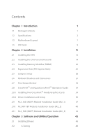
) 22 2.4 Expansion Slots (PCI Express Slots) 25 2.5 Jumpers Setup 26 2.6 Onboard Headers and Connectors 27 2.7 Post Status Checker 33 2.8 CrossFireXTM and Quad CrossFireXTM Operation Guide 34 2.8.1 Installing Two CrossFireXTM-Ready Graphics Cards 34 2.8.2 Driver Installation and Setup - ASRock X570 Pro4 | User Manual - Page 5
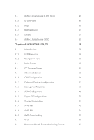
3.3.1 UI Overview 49 3.3.2 Apps 50 3.3.3 BIOS & Drivers 53 3.3.4 Setting 54 3.4 ASRock Polychrome SYNC 55 Chapter 4 UEFI SETUP UTILITY 58 4.1 AMD CBS 73 4.4.8 AMD PBS 74 4.4.9 AMD Overclocking 75 4.5 Tools 76 4.6 Hardware Health Event Monitoring - ASRock X570 Pro4 | User Manual - Page 6
4.7 Security Screen 80 4.8 Boot Screen 81 4.9 Exit Screen 83 - ASRock X570 Pro4 | User Manual - Page 7
may find the latest VGA cards and CPU support list on ASRock's website as well. ASRock website http://www.asrock.com. 1.1 Package Contents • ASRock X570 Pro4 Motherboard (ATX Form Factor) • ASRock X570 Pro4 Quick Installation Guide • ASRock X570 Pro4 Support CD • 2 x Serial ATA (SATA) Data Cables - ASRock X570 Pro4 | User Manual - Page 8
Capacitor design • 2oz Copper PCB • Supports AMD AM4 socket RyzenTM 2000 and 3000 series processors • Digi Power design • 10 Power Phase design Chipset • AMD X570 Memory • Dual Channel DDR4 Memory Technology • 4 x DDR4 DIMM Slots • AMD Ryzen series CPUs (Matisse) support DDR4 4066+ (OC)/3466(OC - ASRock X570 Pro4 | User Manual - Page 9
X570 Pro4 Graphics AMD Ryzen series CPUs (Pinnacle Ridge) • 2 x PCI Express 3.0 x16 Slots (PCIE1/PCIE3: single at x16 (PCIE1); dual at x16 (PCIE1) / x4 (PCIE3))* AMD Ryzen series CPUs (Picasso) • 2 x PCI Express 3.0 x16 Slots (PCIE1/PCIE3: single at x8 (PCIE1); dual at x8 (PCIE1) / x4 (PCIE3))* * - ASRock X570 Pro4 | User Manual - Page 10
Supports Wake-On-LAN • Supports Lightning/ESD Protection • Supports Energy Efficient Ethernet 802.3az • Supports Supports ESD Protection) • 1 x USB 3.2 Gen2 Type-C Port (10 Gb/s) (Supports ESD Protection) • 6 x USB 3.2 Gen1 Ports (Supports x Hyper M.2 Socket (M2_3), supports M Key type 2230/2242/2260 - ASRock X570 Pro4 | User Manual - Page 11
X570 Pro4 Connector • 1 x COM Port Header • 1 x TPM Header • 1 x SPI TPM Header • 1 x Power LED and Speaker Header • 2 x RGB LED Headers * Support in total up to 12V/3A, 36W LED Strip • 1 x Addressable LED Header * Supports in total up to 5V/3A, 15W LED Strip • 1 x CPU Fan Connector (4-pin) * The - ASRock X570 Pro4 | User Manual - Page 12
please visit our website: http://www.asrock.com Please realize that there is a certain risk involved with overclocking, including adjusting the setting in the BIOS, applying Untied Overclocking Technology, or using third-party overclocking tools. Overclocking may affect your system's stability, or - ASRock X570 Pro4 | User Manual - Page 13
1 RGB_LED2 PS2 Keyboard /Mouse USB 3.2 Gen1 T: USB1 B: USB2 DP1 HDMI1 X570 PRO4 DDR4_A1 (64 bit, 288-pin module) DDR4_A2 (64 bit, 288-pin module) DDR4_B1 (64 bit, 288-pin module) DDR4_B2 (64 bit, 288-pin module) ATXPWR1 SOCKET AM4 USB 3.2 Gen1 T: USB3 B: USB4 Top: LINE IN Center: FRONT Bottom - ASRock X570 Pro4 | User Manual - Page 14
(DDR4_A1, DDR4_B1) 5 2 x 288-pin DDR4 DIMM Slots (DDR4_A2, DDR4_B2) 6 RGB LED Header (RGB_LED2) 7 ATX Power Connector (ATXPWR1) 8 USB 3.2 Gen1 Header (USB3_7_8) 9 AMD LED Fan USB Header (USB_1) 10 SPI TPM Header (SPI_TPM_J1) 11 Chassis Fan / Waterpump Fan Connector (CHA_FAN1/WP) 12 SATA3 Connector - ASRock X570 Pro4 | User Manual - Page 15
1.4 I/O Panel 1 X570 Pro4 4 2 3 5 12 11 10 9 8 7 6 No. Description No. Description 1 PS/2 Mouse/Keyboard Port 7 USB 3.2 Gen1 Ports (USB3_5_6) 2 USB 3.2 Gen2 Type-A Port (USB31_TA_1) 8 USB 3.2 Gen2 Type-C Port (USB31_TC_1) 3 - ASRock X570 Pro4 | User Manual - Page 16
* There are two LEDs on each LAN port. Please refer to the table below for the LAN port LED indications. ACT/LINK LED SPEED LED LAN Port Activity / Link LED Status Off Blinking On Description No Link Data Activity Link Speed LED Status Off Orange Green Description 10Mbps connection 100Mbps - ASRock X570 Pro4 | User Manual - Page 17
X570 Pro4 Chapter 2 Installation This is an ATX form factor motherboard. Before you install the motherboard, study the configuration of your chassis to ensure that the motherboard - ASRock X570 Pro4 | User Manual - Page 18
2.1 Installing the CPU Unplug all power cables before installing the CPU. 1 2 12 English - ASRock X570 Pro4 | User Manual - Page 19
X570 Pro4 3 13 English - ASRock X570 Pro4 | User Manual - Page 20
Heatsink After you install the CPU into this motherboard, it is necessary to install a larger heatsink and cooling fan to dissipate heat. You also need to spray thermal grease between the CPU and the heatsink to improve heat dissipation. Make sure that the CPU - ASRock X570 Pro4 | User Manual - Page 21
X570 Pro4 3 4 CPU_FAN1 15 English - ASRock X570 Pro4 | User Manual - Page 22
Installing the AM4 Box Cooler SR2 1 2 16 English - ASRock X570 Pro4 | User Manual - Page 23
X570 Pro4 3 17 English - ASRock X570 Pro4 | User Manual - Page 24
4 CPU_FAN1 18 English - ASRock X570 Pro4 | User Manual - Page 25
Installing the AM4 Box Cooler SR3 1 X570 Pro4 2 19 English - ASRock X570 Pro4 | User Manual - Page 26
3 4 20 English - ASRock X570 Pro4 | User Manual - Page 27
X570 Pro4 5 4-pin FAN cable CPU_FAN1 6 CPU_FAN1 USB_5 Please note that this connector is the interface to the LED control board on the SR3, it requires the AMD utility "SR3 Settings Software" to control the LED. *The diagrams shown here are for reference only. The headers might be in a - ASRock X570 Pro4 | User Manual - Page 28
modules on DDR4_A2 and DDR4_B2 first for better DRAM compatibility on 2 DIMMs configuration. AMD non-XMP Memory Frequency Support Ryzen Series CPUs (Matisse): UDIMM Memory Slot A1 A2 B1 B2 Frequency (Mhz) - SR - - 3200 - DR - - 3200 - SR - SR 3200 - DR - DR 3200 SR SR - ASRock X570 Pro4 | User Manual - Page 29
Ryzen Series CPUs (Picasso): UDIMM/SO-DIMMs Memory Slot # of DIMMs on # of Ranks the Channel per DIMM 1.20V 1 of 1 1 of 2 SR: 2933 xR DR: 2677 SR: 2667 xR-0 DR: SR: Single rank DIMM, 1Rx4 or 1Rx8 on DIMM module label DR: Dual rank DIMM, 2Rx4 or 2Rx8 on DIMM module label X570 Pro4 English 23 - ASRock X570 Pro4 | User Manual - Page 30
The DIMM only fits in one correct orientation. It will cause permanent damage to the motherboard and the DIMM if you force the DIMM into the slot at incorrect orientation. 1 2 3 24 English - ASRock X570 Pro4 | User Manual - Page 31
X570 Pro4 2.4 Expansion Slots (PCI Express Slots) There are 4 PCI Express slots on the motherboard. Before installing an expansion Gen3x4 Gen3x4 For a better thermal environment, please connect a chassis fan to the motherboard's chassis fan connector (CHA_FAN1/WP, CHA_FAN2/WP or CHA_FAN3/WP) when - ASRock X570 Pro4 | User Manual - Page 32
2.5 Jumpers Setup The illustration shows how jumpers are setup. When the jumper cap is placed on the pins, the jumper is "Short". If no jumper cap is placed on the pins, the jumper is "Open". Clear CMOS Jumper (CLRCMOS1) (see p.7, No. 19) 2-pin Jumper Short: Clear CMOS Open: Default CLRCMOS1 - ASRock X570 Pro4 | User Manual - Page 33
X570 Pro4 2.6 Onboard Headers and Connectors Onboard headers and connectors are NOT jumpers. Do NOT place jumper caps over these headers and connectors. Placing jumper caps over the headers and connectors will cause permanent damage to the motherboard. System Panel Header (9-pin PANEL1) (see p.7, - ASRock X570 Pro4 | User Manual - Page 34
SATA3_1 SATA3_7 SATA3_5 SATA3_3 SATA3_4 These eight SATA3 connectors support SATA data cables for internal storage devices with up to 6.0 Gb/s data transfer rate. AMD LED Fan USB Header (4-pin USB_1) (see p.7, No. 9) 1 GND P- P+ USB_PWR This header is used for connecting the USB connector on - ASRock X570 Pro4 | User Manual - Page 35
X570 Pro4 Front Panel Audio Header (9-pin HD_AUDIO1) (see p.7, No. 27) GND PRESENCE# MIC_RET OUT_RET 1 OUT2_L J_SENSE OUT2_R MIC2_R MIC2_L This header is for connecting audio devices to the front audio panel. 1. High Definition Audio supports Jack Sensing, but the panel wire on the chassis must - ASRock X570 Pro4 | User Manual - Page 36
Pin water cooling CPU fan connector. If you plan to connect a 3-Pin CPU water cooler fan, please connect it plug the PCIe power cable to this connector. TPM Header (17-pin TPMS1) (see p.7, No. 26) 1 GND S_PWRDWN# SERIRQ# GND This connector supports Trusted Platform Module (TPM) system, which - ASRock X570 Pro4 | User Manual - Page 37
X570 Pro4 SPI TPM Header (13-pin SPI_TPM_J1) (see p.7, No. 10) Thunderbolt AIC Connector (5-pin TB1) (see p.7, No. 28) RGB LED Headers (4-pin RGB_LED1) (see p.7, card to PCIE3 (default slot). * For the further information, please visit www.asrock.com. 1 12V G R B RGB header is used to connect RGB - ASRock X570 Pro4 | User Manual - Page 38
Caution: Never install the Addressable LED cable in the wrong orientation; otherwise, the cable may be damaged. * Please refer to page 56 for further instructions on this header. Serial Port Header (9-pin COM1) (see p.7, No. 25) RRXD1 DDTR#1 DDSR#1 CCTS#1 1 RRI#1 RRTS#1 GND TTXD1 DDCD#1 This COM1 - ASRock X570 Pro4 | User Manual - Page 39
X570 Pro4 2.7 Post Status Checker Post Status Checker (PSC) diagnoses the computer when users power on the machine. It emits a red light to indicate whether the CPU, memory, VGA or storage is dysfunctional. The lights go off if the four mentioned above are functioning normally. 33 English - ASRock X570 Pro4 | User Manual - Page 40
that your graphics card driver supports AMD CrossFireXTM technology. Download the drivers from the AMD's website manuals for detailed installation guide. 2.8.1 Installing Two CrossFireXTM-Ready Graphics Cards Step 1 Insert one graphics card into PCIE1 slot and the other graphics card to PCIE3 slot - ASRock X570 Pro4 | User Manual - Page 41
X570 Pro4 Step 3 Connect a VGA cable or a DVI cable to the monitor connector or the DVI connector of the graphics card that is inserted to PCIE1 slot. 35 English - ASRock X570 Pro4 | User Manual - Page 42
optional download. We recommend using this utility to uninstall any previously installed Catalyst drivers prior to installation. Please check AMD's website for AMD driver updates. Step 3 Install the required drivers and CATALYST Control Center then restart your computer. Please check AMD's website - ASRock X570 Pro4 | User Manual - Page 43
X570 Pro4 2.9 M.2_SSD (NGFF) Module Installation Guide (M2_1) The M.2, also known as the Next Generation Form Factor (NGFF), is a small size and versatile card edge connector that aims to replace mPCIe and mSATA. The M.2 Socket (M2_1) supports M Key type 2230/2242/2260/2280/22110 M.2 PCI Express - ASRock X570 Pro4 | User Manual - Page 44
package. Then hand tighten the standoff into the desired nut location on the motherboard. Align and gently insert the M.2 (NGFF) SSD module into the M.2 slot. Please be aware that the M.2 (NGFF) SSD module only fits in one orientation. Step 5 Tighten the screw with a screwdriver to secure the module - ASRock X570 Pro4 | User Manual - Page 45
X570 Pro4 M.2_SSD (NGFF) Module Support List Vendor SanDisk Intel Intel Kingston Samsung Interface PCIe PCIe PCIe PCIe PCIe x4) Samsung XP941-MZHPU512HCGL(Gen2x4) For the latest updates of M.2_SSD (NFGG) module support list, please visit our website for details: http://www.asrock.com English 39 - ASRock X570 Pro4 | User Manual - Page 46
2.10 M.2 WiFi/BT Module Installation Guide (M2_2) The M.2, also known as the Next Generation Form Factor (NGFF), is a small size and versatile card edge connector that aims to replace mPCIe and mSATA. The M.2 Socket (Key E) supports type 2230 WiFi/BT module. * The M.2 socket does not support SATA - ASRock X570 Pro4 | User Manual - Page 47
A A 20o A X570 Pro4 Step 3 Gently insert the WiFi/BT module into the M.2 slot. Please be aware that the module only fits in one orientation. Step 4 Tighten the screw with a screwdriver to secure the module into place. Please do - ASRock X570 Pro4 | User Manual - Page 48
2.11 M.2_SSD (NGFF) Module Installation Guide (M2_3) The M.2, also known as the Next Generation Form Factor (NGFF), is a small size and versatile card edge connector that aims to replace mPCIe and mSATA. The M.2 Socket (M2_3) supports M Key type 2230/2242/2260/2280/22110 M.2 SATA3 6.0 Gb/s module - ASRock X570 Pro4 | User Manual - Page 49
D C B A E D C B A E D C B A X570 Pro4 Step 3 Move the standoff based on the module type and length. The the motherboard. Step 5 Gently insert the M.2 (NGFF) SSD module into the M.2 slot. Please be aware that the M.2 (NGFF) SSD module only fits in one orientation. E D C B - ASRock X570 Pro4 | User Manual - Page 50
the screw as this might damage the module. M.2_SSD (NGFF) Module Support List Vendor SanDisk Intel Intel Kingston Samsung ADATA Crucial ezlink Intel Kingston Kingston the latest updates of M.2_SSD (NFGG) module support list, please visit our website for details: http://www.asrock.com English 44 - ASRock X570 Pro4 | User Manual - Page 51
X570 Pro4 Chapter 3 Software and Utilities Operation 3.1 Installing Drivers The Support CD that comes with the motherboard contains necessary drivers and useful utilities that enhance the motherboard's features. Running The Support CD To begin using the support CD, insert the CD into your CD-ROM - ASRock X570 Pro4 | User Manual - Page 52
features and improved utilities. 3.2.1 Installing A-Tuning A-Tuning can be downloaded from ASRock Live Update & APP Shop. After the installation, you will find the : Operation Mode, OC Tweaker, System Info, FAN-Tastic Tuning and Settings. Operation Mode Choose an operation mode for your computer. - ASRock X570 Pro4 | User Manual - Page 53
OC Tweaker Configurations for overclocking the system. X570 Pro4 System Info View information about the system. *The System Browser tab may not appear for certain models. 47 English - ASRock X570 Pro4 | User Manual - Page 54
Tuning Configure up to five different fan speeds using the graph. The fans will automatically shift to the next speed level when the assigned temperature is met. Settings Configure ASRock A-Tuning. Click to select "Auto run at Windows Startup" if you want A-Tuning to be launched when you start - ASRock X570 Pro4 | User Manual - Page 55
X570 Pro4 3.3 ASRock Live Update & APP Shop The ASRock Live Update & APP Shop is an online store for purchasing and downloading software applications for your ASRock computer. You can quickly and easily install various apps and support utilities. With ASRock Live Update & APP Shop, you can - ASRock X570 Pro4 | User Manual - Page 56
on the right. Please scroll up and down to see more apps listed. You can check the price of the app and whether you have already intalled it or not. - The red icon displays the price or "Free" if the app is free of charge. - The green "Installed" icon means the app - ASRock X570 Pro4 | User Manual - Page 57
X570 Pro4 Step 3 If you want to install the app, click on the red icon to start downloading. Step 4 When installation completes, you can find the green " - ASRock X570 Pro4 | User Manual - Page 58
Upgrading an App You can only upgrade the apps you have already installed. When there is an available new version for your app, you will find the mark of "New Version" appears below the installed app icon. Step 1 Click on the app icon to see more details. Step 2 Click on the yellow icon to start - ASRock X570 Pro4 | User Manual - Page 59
X570 Pro4 3.3.3 BIOS & Drivers Installing BIOS or Drivers When the "BIOS & Drivers" tab is selected, you will see a list of recommended or critical updates for the BIOS or drivers. Please update them all soon. Step 1 Please check the item information before update. Click on Step 2 to see more - ASRock X570 Pro4 | User Manual - Page 60
3.3.4 Setting In the "Setting" page, you can change the language, select the server location, and determine if you want to automatically run the ASRock Live Update & APP Shop on Windows startup. 54 English - ASRock X570 Pro4 | User Manual - Page 61
X570 Pro4 3.4 ASRock Polychrome SYNC ASRock Polychrome SYNC is a lighting control utility specifically designed for that the RGB LED strips do not come with the package. 2. The RGB LED header supports standard 5050 RGB LED strip (12V/G/R/B), with a maximum power rating of 3A (12V) and length within - ASRock X570 Pro4 | User Manual - Page 62
LED Strip Connect your Addressable RGB LED strip to the Addressable LED Header (ADDR_LED1) on the motherboard. ADDR_LED1 1 GND DO_ADDR VOUT 1 RGB LED strips do not come with the package. 2. The RGB LED header supports WS2812B addressable RGB LED strip (5V/Data/ GND), with a maximum power rating of - ASRock X570 Pro4 | User Manual - Page 63
X570 Pro4 ASRock Polychrome SYNC Utility Now you can adjust the RGB LED color through the ASRock RGB LED utility. Download this utility from the ASRock Live Update & APP Shop and start coloring your PC style your way! Drag the tab to customize your preference. Toggle on/off the RGB LED - ASRock X570 Pro4 | User Manual - Page 64
screen has a menu bar with the following selections: Main For setting system time/date information OC Tweaker For overclocking configurations Advanced For advanced system configurations Tool Useful tools H/W Monitor Displays current hardware status Security For security settings Boot - ASRock X570 Pro4 | User Manual - Page 65
X570 Pro4 4.1.2 Navigation Keys Use < > key or < > key to choose among the selections on the menu bar, and use < > key or < > key to move the cursor up - ASRock X570 Pro4 | User Manual - Page 66
4.2 Main Screen When you enter the UEFI SETUP UTILITY, the Main screen will appear and display the system overview. 60 English - ASRock X570 Pro4 | User Manual - Page 67
In the OC Tweaker screen, you can set up overclocking features. X570 Pro4 Because the UEFI software is constantly being updated, the Disable to achieve higher clock speeds when overclocking. CPU Frequency and Voltage Change If this item is set to [Manual], the multiplier and voltage will be set - ASRock X570 Pro4 | User Manual - Page 68
re-enable SMT, a power cycle is needed after selecting [Auto]. Warning: S3 is not supported on systems where SMT is disabled. DRAM Timing Configuration Load XMP Setting Load XMP settings to overclock the memory and perform beyond standard specifications. DRAM Information Browse the serial presence - ASRock X570 Pro4 | User Manual - Page 69
X570 Pro4 Voltage Configuration Voltage Mode [OC] If this option is selected, there is larger range voltage for overclocking. [Stable] If this option is selected, there is smaller range voltage for stable system. CPU Vcore Voltage Configure the voltage for the CPU Vcore. CPU - ASRock X570 Pro4 | User Manual - Page 70
VDDP Configure the voltage for the VDDP. PREM VDDCR_SOC Voltage Use this to select PREM VDDCR_SOC Voltage. The default value is [Auto]. Save User Default Type a profile name and press enter to save your settings as user default. Load User Default Load previously saved user defaults. Save User UEFI - ASRock X570 Pro4 | User Manual - Page 71
X570 Pro4 4.4 Advanced Screen In this section, you may set the configurations for the following items: CPU Configuration, Onboard Devices Configuration, Storage Configuration, ACPI Configuration, Super IO Configuration, Trusted Computing , AMD CBS, AMD PBS and AMD Overclocking. Setting wrong values - ASRock X570 Pro4 | User Manual - Page 72
4.4.1 CPU Configuration PSS Support Use this to enable or disable the generation of ACPI_PPC, _PSS, and _PCT SMT, a power cycle is needed after selecting [Auto]. Warning: S3 is not supported on systems where SMT is disabled. AMD fTPM Switch Use this to enable or disable AMD CPU fTPM. 66 English - ASRock X570 Pro4 | User Manual - Page 73
4.4.2 Onboard Devices Configuration X570 Pro4 SR-IOV Support Enable/disable the SR-IOV (Single Root IO Virtualization Support) if the system has SR-IOV capable PCIe devices. UMA Frame buffer Size (Only for processor with integrated graphics) This item allows you to set - ASRock X570 Pro4 | User Manual - Page 74
WAN Radio Configure the WiFi module's connectivity. BT On/Off Enable/disable the bluetooth. 68 English - ASRock X570 Pro4 | User Manual - Page 75
4.4.3 Storage Configuration X570 Pro4 English 69 - ASRock X570 Pro4 | User Manual - Page 76
4.4.4 ACPI Configuration Suspend to RAM It is recommended to select auto for ACPI S3 power saving. PS/2 Keyboard S4/S5 Wakeup Support Allow the system to be waked up by a PS/2 Keyboard in S4/S5. PCIE Devices Power On Allow the system to be waked up by a - ASRock X570 Pro4 | User Manual - Page 77
4.4.5 Super IO Configuration X570 Pro4 Serial Port Enable or disable the Serial port. Serial Port Address Select the address of the Serial port. PS2 Y-Cable Enable the PS2 Y-Cable or set this option to Auto. 71 English - ASRock X570 Pro4 | User Manual - Page 78
4.4.6 Trusted Computing Security Device Support Enable or disable BIOS support for security device. 72 English - ASRock X570 Pro4 | User Manual - Page 79
4.4.7 AMD CBS X570 Pro4 The AMD CBS menu accesses AMD specific features. English 73 - ASRock X570 Pro4 | User Manual - Page 80
4.4.8 AMD PBS The AMD PBS menu accesses AMD specific features. 74 English - ASRock X570 Pro4 | User Manual - Page 81
4.4.9 AMD Overclocking X570 Pro4 The AMD Overclocking menu accesses options for configuring CPU frequency and voltage. English 75 - ASRock X570 Pro4 | User Manual - Page 82
Tools RGB LED ASRock Polychrome SYNC allows you to adjust the RGB LED color to your liking. Easy Driver Installer For users that don't have an optical disk drive to install the drivers from our support CD, Easy Driver Installer is a handy tool in the UEFI that installs the LAN driver to your system - ASRock X570 Pro4 | User Manual - Page 83
X570 Pro4 4.6 Hardware Health Event Monitoring Screen This section allows you to monitor the status of the hardware on your system, including the parameters of the CPU temperature, motherboard temperature, fan speed and voltage. Fan Tuning Measure Fan Min Duty Cycle. Fan-Tastic Tuning Select a fan - ASRock X570 Pro4 | User Manual - Page 84
PWM mode or DC mode for CPU Fan 2 . CPU Fan 2 Setting Select a fan mode for CPU Fan 2, or choose Customize to set 5 CPU temperatures and assign a respective fan speed for each temperature. CPU Fan 2 Temp Source Select a fan temperature source for CPU Fan 2. CHA_FAN1 / WP Switch Select CHA_FAN1 or - ASRock X570 Pro4 | User Manual - Page 85
X570 Pro4 Chassis Fan 3 Control Mode Select PWM mode or DC mode for Chassis Fan 3 . Chassis Fan 3 Setting Select a fan mode for Chassis Fan 3, or choose Customize to set 5 CPU temperatures and assign a respective fan speed for each temperature. Chassis Fan 3 Temp Source Select a fan temperature - ASRock X570 Pro4 | User Manual - Page 86
are unable to change the settings in the UEFI Setup Utility. Leave it blank and press enter to remove the password. Secure Boot Enable to support Secure Boot. 80 English - ASRock X570 Pro4 | User Manual - Page 87
X570 Pro4 4.8 Boot Screen This section displays the available devices on your system for you to configure the boot settings and the boot priority. Fast Boot Fast - ASRock X570 Pro4 | User Manual - Page 88
messages or configure the AddOn ROM if you've enabled Full Screen Logo. Disable for faster boot speed. CSM (Compatibility Support Module) CSM Enable to launch the Compatibility Support Module. Please do not disable unless you're running a WHCK test. Above 4G Decoding Enable or disable 64bit capable - ASRock X570 Pro4 | User Manual - Page 89
4.9 Exit Screen X570 Pro4 Save Changes and Exit When you select this option the following message, "Save configuration changes and exit setup?" will pop out. Select [OK] to save - ASRock X570 Pro4 | User Manual - Page 90
dealer for further information. For technical questions, please submit a support request form at https://event.asrock.com/tsd.asp ASRock Incorporation 2F., No.37, Sec. 2, Jhongyang S. Rd., Beitou District, Taipei City 112, Taiwan (R.O.C.) ASRock EUROPE B.V. Bijsterhuizen 11-11 6546 AR Nijmegen The - ASRock X570 Pro4 | User Manual - Page 91
FCC Part 2 Section 2.1077(a) Responsible Party Name: ASRock Incorporation Address: 13848 Magnolia Ave, Chino, CA91710 Phone/Fax No: +1-909-590-8308/+1-909-590-1026 hereby declares that the product Product Name : Motherboard Model Number : X570 Pro4 Conforms to the following speci cations: FCC Part15 - ASRock X570 Pro4 | User Manual - Page 92
EU Declaration of Conformity For the following equipment: Motherboard (Product Name) X570 Pro4 / ASRock (Model Designation / Trade Name) ASRock Incorporation (Manufacturer Name) 2F., No.37, Sec. 2, Jhongyang S. Rd., Beitou District, Taipei City 112, Taiwan (R.O.C.) (Manufacturer Address) ڛEMC
-
 1
1 -
 2
2 -
 3
3 -
 4
4 -
 5
5 -
 6
6 -
 7
7 -
8
-
9
-
10
-
11
-
12
-
13
-
14
-
15
-
16
-
17
-
18
-
19
-
20
-
21
-
22
-
23
-
24
-
25
-
26
-
27
-
28
-
29
-
30
-
31
-
32
-
33
-
34
-
35
-
36
-
37
-
38
-
39
-
40
-
41
-
42
-
43
-
44
-
45
-
46
-
47
-
48
-
49
-
50
-
51
-
52
-
53
-
54
-
55
-
56
-
57
-
58
-
59
-
60
-
61
-
62
-
63
-
64
-
65
-
66
-
67
-
68
-
69
-
70
-
71
-
72
-
73
-
74
-
75
-
76
-
77
-
78
-
79
-
80
-
81
-
82
-
83
-
84
-
85
-
86
-
87
-
88
-
89
-
90
-
91
-
92
 |
 |
