ASRock Z170 Extreme7 User Manual
ASRock Z170 Extreme7 Manual
 |
View all ASRock Z170 Extreme7 manuals
Add to My Manuals
Save this manual to your list of manuals |
ASRock Z170 Extreme7 manual content summary:
- ASRock Z170 Extreme7 | User Manual - Page 1
- ASRock Z170 Extreme7 | User Manual - Page 2
change without notice, and should not be constructed as a commitment by ASRock. ASRock assumes no responsibility for any errors or omissions that may appear in CALIFORNIA, USA ONLY he Lithium battery adopted on this motherboard contains Perchlorate, a toxic substance controlled in Perchlorate Best - ASRock Z170 Extreme7 | User Manual - Page 3
he terms HDMI™ and HDMI High-Deinition Multimedia Interface, and the HDMI logo are trademarks or registered trademarks of HDMI Licensing LLC in the United States and other countries. Manufactured under license under U.S. Patent Nos: 5,956,674; 5,974,380; 6,487,535; 7,003,467 & other U.S. and - ASRock Z170 Extreme7 | User Manual - Page 4
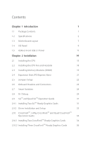
Motherboard Layout 7 1.4 I/O Panel 9 1.5 ASRock Front USB 3.1 Panel 11 Chapter 2 Installation 14 2.1 Installing the CPU 15 2.2 Installing the CPU 2.9 SLITM and Quad SLITM Operation Guide 31 2.9.1 Installing Two SLITM-Ready Graphics Cards 31 2.9.2 Driver Installation and Setup 33 2.10 - ASRock Z170 Extreme7 | User Manual - Page 5
37 2.11 M.2_SSD (NGFF) Module Installation Guide 38 Chapter 3 Software and Utilities Operation 41 3.1 Installing Drivers 41 3.2 A-Tuning 42 3.3 ASRock Live Update & APP Shop 46 3.3.1 UI Overview 46 3.3.2 Apps 47 3.3.3 BIOS & Drivers 50 3.3.4 Setting 51 3.4 Enabling USB Ports - ASRock Z170 Extreme7 | User Manual - Page 6
4.4.7 USB Coniguration 80 4.4.8 Trusted Computing 81 4.5 Tools 82 4.6 Hardware Health Event Monitoring Screen 86 4.7 Security Screen 88 4.8 Boot Screen 89 4.9 Exit Screen 92 - ASRock Z170 Extreme7 | User Manual - Page 7
ind the latest VGA cards and CPU support list on ASRock's website as well. ASRock website http://www.asrock.com. 1.1 Package Contents • ASRock Z170 Extreme7 Motherboard (ATX Form Factor) • ASRock Z170 Extreme7 Quick Installation Guide • ASRock Z170 Extreme7 Support CD • 4 x Serial ATA (SATA) Data - ASRock Z170 Extreme7 | User Manual - Page 8
1151) • Digi Power design • 12 Power Phase design • Supports Intel® Turbo Boost 2.0 Technology • Supports Intel® K-Series unlocked CPUs • Supports ASRock BCLK Full-range Overclocking • Supports ASRock Hyper BCLK Engine Chipset • Intel® Z170 Memory • Dual Channel DDR4 Memory Technology • 4 x DDR4 - ASRock Z170 Extreme7 | User Manual - Page 9
Z170 Extreme7+ Audio • Supports Intel® HD Graphics Built-in Visuals : Intel® Quick Sync Video with Protection (Realtek ALC1150 Audio Codec) • Premium Blu-ray Audio support • Supports Surge Protection (ASRock Full Spike Protection) • Supports Purity SoundTM 3 - Nichicon Fine Gold Series Audio Caps - - ASRock Z170 Extreme7 | User Manual - Page 10
Full Spike Protection)) • 1 x USB 3.1 Type-C Port (10 Gb/s) (Supports ESD Protection (ASRock Full Spike Protection)) • 6 x SATA3 6.0 Gb/s Connectors by Intel® Z170, support RAID (RAID 0, RAID 1, RAID 5, RAID 10, Intel Rapid Storage Technology 14 and Intel Smart Response Technology), NCQ, AHCI and - ASRock Z170 Extreme7 | User Manual - Page 11
Z170 Extreme7+ • 3 x SATA Express 10 Gb/s Connectors* * Support to be announced * M2_1, SATA3_0, SATA3_1 and SATA_EXP0 share lanes. If either one of them is in use, the others will be disabled. * M2_2, SATA3_2, - ASRock Z170 Extreme7 | User Manual - Page 12
into the ISO ile is required. Please refer to page 52 for more detailed instructions. * For the updated Windows® 10 driver, please visit ASRock's website for details: http://www.asrock.com • FCC, CE, WHQL • ErP/EuP Ready (ErP/EuP ready power supply is required) * For detailed product information - ASRock Z170 Extreme7 | User Manual - Page 13
1.3 Motherboard Layout Z170 Extreme7+ 1 2 CPU_FAN1 ATX12V1 3 45 6 CPU_FAN2 7 CHA_FAN4 CLRCBTN1 Power 8 Reset 9 1 BIOS_SEL1 A B BIOS_A_LED BIOS_B_LED Dr. Debug CMOS Battery 128Mb BIOS BIOS_A1 128Mb BIOS BIOS_B1 PLED PWRBTN 1 HDLED RESET PANEL1 USB3_4 USB5_6 1 1 USB7_8 - ASRock Z170 Extreme7 | User Manual - Page 14
No. Description 1 ATX 12V Power Connector (ATX12V1) 2 CPU Fan Connector (CPU_FAN1) 3 CPU Fan Connector (CPU_FAN2) 4 2 x 288-pin DDR4 DIMM Slots (USB5_6) 27 USB 2.0 Header (USB3_4) 28 System Panel Header (PANEL1) 29 BIOS Selection Switch (BIOS_SEL1) 30 Clear CMOS Jumper (CLRMOS1) 31 TPM Header (TPMS1) - ASRock Z170 Extreme7 | User Manual - Page 15
1.4 I/O Panel 1 2 Z170 Extreme7+ 57 3 4 68 17 16 15 13 14 12 11 10 9 No. Description 1 USB 2.0 Ports (USB12) 2 DVI-D Port 3 LAN RJ-45 Port (Intel® I219V)* 4 LAN RJ- - ASRock Z170 Extreme7 | User Manual - Page 16
* here are two LEDs on each LAN port. Please refer to the table below for the LAN port LED indications. ACT/LINK LED SPEED LED LAN Port Activity / Link LED Status Of Blinking On Description No Link Data Activity Link Speed LED Status Of Orange Green Description 10Mbps connection 100Mbps - ASRock Z170 Extreme7 | User Manual - Page 17
Z170 Extreme7+ 1.5 ASRock Front USB 3.1 Panel Speciications Dimension • 75mm (W) x 42.8mm (H) x 148mm (L) Controller • ASMedia ASM1142 Controller Front Panel I/O • 1 x USB 3.1 Type-A Port (10 Gb/s) (Supports ESD Protection (ASRock Full Spike Protection)) * For charging Type-A USB devices, we - ASRock Z170 Extreme7 | User Manual - Page 18
Front USB 3.1 Panel Front USB 3.1 Panel Front USB 3.1 Panel ASRock Front USB 3.1 Panel Installation Guide Step 1 Prepare the bundled ASRock Front USB 3.1 Panel, SATA Express Cable, USB Power Cable and screws. Step 2 Connect one end of the SATA Express Cable to the SATA Express Connector - ASRock Z170 Extreme7 | User Manual - Page 19
USB 3.0 USB 3.0 English Z170 Extreme7+ Step 5 Screw ASRock Front USB 3.1 Panel to the drive bay with the other end of the SATA Express Cable to the SATA Express Connector on the motherboard. SATA3_4_5 SATA3_A1_A2 SATA3_A3_A4 SATA_EXP0 SATA3_1_3 SATA3_0_2 Step 8 Connect the other end of the USB - ASRock Z170 Extreme7 | User Manual - Page 20
Pre-installation Precautions Take note of the following precautions before you install motherboard components or change any motherboard settings. • Make sure to unplug the power cord before installing or removing the motherboard components. Failure to do so may cause physical injuries and damages to - ASRock Z170 Extreme7 | User Manual - Page 21
Z170 Extreme7+ 2.1 Installing the CPU 1. Before you insert the 1151-Pin CPU into the socket, please check if the PnP cap is on the socket, if the CPU surface is unclean, or if there are any bent pins in the socket. Do not force to insert the CPU into the socket if above situation is found. Otherwise - ASRock Z170 Extreme7 | User Manual - Page 22
4 5 16 3 English - ASRock Z170 Extreme7 | User Manual - Page 23
Z170 Extreme7+ Please save and replace the cover if the processor is removed. he cover must be placed if you wish to return the motherboard for ater service. 17 English - ASRock Z170 Extreme7 | User Manual - Page 24
2.2 Installing the CPU Fan and Heatsink 1 2 CPU_FAN English 18 - ASRock Z170 Extreme7 | User Manual - Page 25
Z170 Extreme7+ 2.3 Installing Memory Modules (DIMM) his motherboard provides four 288-pin DDR4 (Double Data Rate 4) DIMM slots, and supports Dual Channel Memory Technology. 1. For dual channel coniguration, you always need to install identical (the same brand, speed, size and chip-type) DDR4 DIMM - ASRock Z170 Extreme7 | User Manual - Page 26
1 2 3 20 English - ASRock Z170 Extreme7 | User Manual - Page 27
Z170 Extreme7+ 2.4 Expansion Slots (PCI Express Slots) here are 6 PCI Express slots and 1 mini-PCI Express slot on the motherboard. Before cards. mini-PCIe slot: MINI_PCIE1 (mini-PCIe slot) is used for WiFi module. PCIe Slot Conigurations PCIE2 PCIE3 PCIE4 PCIE6 Single Graphics x16 N/A - ASRock Z170 Extreme7 | User Manual - Page 28
short pin2 and pin3 on CLRMOS1 for 5 seconds. However, please do not clear the CMOS right ater you update the BIOS. If you need to clear the CMOS when you just inish updating the BIOS, you must boot up the system irst, and then shut it down before you do the clear-CMOS action - ASRock Z170 Extreme7 | User Manual - Page 29
Z170 Extreme7+ 2.6 Onboard Headers and Connectors Onboard headers and connectors are NOT jumpers. Do NOT place jumper caps over these headers and connectors. Placing jumper caps over the headers and connectors will cause permanent damage to the motherboard. System Panel Header (9-pin PANEL1) (see - ASRock Z170 Extreme7 | User Manual - Page 30
to this header. SATA3_2 SATA3_0 SATA3_A2 SATA3_A4 SATA3_3 hese ten SATA3 connectors support SATA data cables for internal storage devices with up to 6.0 Gb/s minimize the boot time, use Intel® Z170 SATA ports (SATA3_0) for your bootable devices. SATA3_4 SATA3_A1 SATA3_A3 SATA3_1 SATA3_5 - ASRock Z170 Extreme7 | User Manual - Page 31
p.7, No. 23) SATA_EXP0 SATA3_1 SATA3_0 SATA_EXP1 SATA3_3 SATA3_2 Z170 Extreme7+ Please connect either SATA or PCIe storage devices to GND DUMMY 1 GND P+ PUSB_PWR here are three headers on this motherboard. Each USB 2.0 header can support two ports. USB 3.0 Headers (19-pin USB3_5_6) (see p.7, - ASRock Z170 Extreme7 | User Manual - Page 32
must support HDA to function correctly. Please follow the instructions in our manual and chassis manual to install your system. 2. If you use an AC'97 audio 4 FAN_SPEED_CONTROL his motherboard provides a 4-Pin CPU fan (Quiet Fan) connector. If you plan to connect a 3-Pin CPU fan, please connect - ASRock Z170 Extreme7 | User Manual - Page 33
Z170 Extreme7+ ATX Power 3V LAD3 PCIRST # FRAM E PCICLK 12 24 1 13 8 5 4 1 his motherboard provides a 24-pin ATX power connector. To use a 20-pin ATX power supply, GND TTXD1 DDCD#1 his COM1 header supports a serial port module. his connector supports Trusted Platform Module (TPM) system, - ASRock Z170 Extreme7 | User Manual - Page 34
to duplicate a working copy of the BIOS iles to the primary BIOS to ensure normal system operation. For safety issues, users are not able to update the backup BIOS manually. Users may refer to the BIOS LEDs (BIOS_A_LED or BIOS_B_LED) to identify which BIOS is currently activated. English 28 - ASRock Z170 Extreme7 | User Manual - Page 35
Z170 Extreme7+ 2.8 Dr. Debug Dr. Debug is used to provide code information, which makes troubleshooting even easier. Please see the diagrams below for reading the Dr. Debug codes. Code Description 00 Please check if the CPU is installed correctly and then clear CMOS. 0d Problem related to - ASRock Z170 Extreme7 | User Manual - Page 36
related to USB devices. Please try removing all USB devices. b7 Problem related to memory. Please re-install the CPU and memory then clear CMOS. If the problem still exists, please install only one memory module or try using other memory modules. d6 he VGA could not be recognized. Please - ASRock Z170 Extreme7 | User Manual - Page 37
Z170 Extreme7+ 2.9 SLITM and Quad SLITM Operation Guide his motherboard supports NVIDIA® SLITM and Quad SLITM (Scalable are NVIDIA® certiied. 2. Make sure that your graphics card driver supports NVIDIA® SLITM technology. Download the drivers from the NVIDIA® website: www.nvidia.com 3. Make sure - ASRock Z170 Extreme7 | User Manual - Page 38
SLI_ Bridge_2S Card to the goldingers on each graphics card. Make sure the ASRock SLI_ Bridge_2S Card is irmly in place. SLI_Bridge_2S Card ASRock SLI_Bridge_2S Card Step 4 Connect a VGA cable or a DVI cable to the monitor connector or the DVI connector of the graphics card that is inserted to - ASRock Z170 Extreme7 | User Manual - Page 39
Z170 Extreme7+ 2.9.2 Driver Installation and Setup Install the graphics card drivers to your system. Ater that, you can enable the Multi-Graphics Processing Unit (GPU) in the NVIDIA® nView system tray utility. Please follow the below - ASRock Z170 Extreme7 | User Manual - Page 40
Guide his motherboard supports CrossFireXTM, 3-way CrossFireXTM and Quad CrossFireXTM that allows you to install up to three identical PCI Express x16 graphics cards. 1. You should only use identical CrossFireXTM-ready graphics cards that are AMD certiied. 2. Make sure that your graphics card driver - ASRock Z170 Extreme7 | User Manual - Page 41
Z170 Extreme7+ Step 3 Connect a VGA cable or a DVI cable to the monitor connector or the DVI connector of the graphics card that is inserted to PCIE2 slot. 35 English - ASRock Z170 Extreme7 | User Manual - Page 42
to connect the graphics cards on PCIE4 and PCIE6 slots. (he CrossFire Bridge is provided with the graphics card you purchase, not bundled with this motherboard. Please refer to your graphics card vendor for details.) Step 3 Connect a VGA cable or a DVI cable to the monitor connector or the DVI - ASRock Z170 Extreme7 | User Manual - Page 43
Z170 Extreme7+ 2.10.3 Driver Installation and Setup Step 1 Power on your computer and boot into OS. Step 2 Remove the AMD drivers if you have any VGA drivers Catalyst drivers prior to installation. Please check AMD's website for AMD driver updates. Step 3 Install the required drivers and CATALYST - ASRock Z170 Extreme7 | User Manual - Page 44
2.11 M.2_SSD (NGFF) Module Installation Guide The M.2, also known as the Next Generation Form Factor (NGFF), is a small size and versatile card edge connector that aims to replace mPCIe and mSATA. The Ultra M.2 Sockets support M.2 PCI Express module up to Gen3 x4 (32 Gb/s). * M2_1, SATA3_0, SATA3_1 - ASRock Z170 Extreme7 | User Manual - Page 45
E D C B A C B A E D C B A Z170 Extreme7+ Step 3 Move the standof based on the module type and length. ilm on the nut to be used. Hand tighten the standof into the desired nut location on the motherboard. Step 5 Align and gently insert the M.2 (NGFF) SSD module into the M.2 slot. Please - ASRock Z170 Extreme7 | User Manual - Page 46
the screw as this might damage the module. M.2_SSD (NGFF) Module Support List Vendor ADATA ADATA ADATA Crucial Crucial Intel Kingston Kingston Plextor Plextor Samsung Samsung latest updates of M.2_SSD (NFGG) module support list, please visit our website for details: http://www.asrock.com - ASRock Z170 Extreme7 | User Manual - Page 47
Z170 Extreme7+ Chapter 3 Software and Utilities Operation 3.1 Installing Drivers he Support CD that comes with the motherboard contains necessary drivers and useful utilities that enhance the motherboard's features. Running The Support CD To begin using the support CD, insert the CD into your CD-ROM - ASRock Z170 Extreme7 | User Manual - Page 48
utilities. 3.2.1 Installing A-Tuning When you install the all-in-one driver to your system from ASRock's support CD, A-Tuning will be auto-installed as well. Ater the System Info, FAN-Tastic Tuning, Tech Service and Settings. Operation Mode Choose an operation mode for your computer. 42 English - ASRock Z170 Extreme7 | User Manual - Page 49
OC Tweaker Conigurations for overclocking the system. Z170 Extreme7+ System Info View information about the system. *he System Browser tab may not appear for certain models. 43 English - ASRock Z170 Extreme7 | User Manual - Page 50
to ive diferent fan speeds using the graph. he fans will automatically shit to the next speed level when the assigned temperature is met. Tech Service Contact Tech Service if you have problems with your computer. Please leave your contact information along with details of the - ASRock Z170 Extreme7 | User Manual - Page 51
Z170 Extreme7+ Settings Conigure ASRock A-Tuning. Click to select "Auto run at Windows Startup" if you want A-Tuning to be launched when you start up the Windows operating system. 45 English - ASRock Z170 Extreme7 | User Manual - Page 52
install various apps and support utilities, such as USB Key, XFast LAN, XFast RAM and more. With ASRock APP Shop, you can optimize your system and keep your motherboard up to date simply with a few clicks. Double-click utility. on your desktop to access ASRock Live Update & APP Shop *You need - ASRock Z170 Extreme7 | User Manual - Page 53
Z170 Extreme7+ 3.3.2 Apps When the "Apps" tab is selected, you will see all the available apps on up and down to see more apps listed. You can check the price of the app and whether you have already intalled it or not. - he red icon displays the price or "Free" if the app is free of charge. - he - ASRock Z170 Extreme7 | User Manual - Page 54
Step 3 If you want to install the app, click on the red icon to start downloading. Step 4 When installation completes, you can ind the green "Installed" icon appears on the upper right corner. English To uninstall it, simply click on the trash can icon . *he trash icon may not appear for certain - ASRock Z170 Extreme7 | User Manual - Page 55
Z170 Extreme7+ Upgrading an App You can only upgrade the apps you have already installed. When there is an available new version for your app, you will - ASRock Z170 Extreme7 | User Manual - Page 56
3.3.3 BIOS & Drivers Installing BIOS or Drivers When the "BIOS & Drivers" tab is selected, you will see a list of recommended or critical updates for the BIOS or drivers. Please update them all soon. Step 1 Please check the item information before update. Click on Step 2 to see more details. - ASRock Z170 Extreme7 | User Manual - Page 57
Z170 Extreme7+ 3.3.4 Setting In the "Setting" page, you can change the language, select the server location, and determine if you want to automatically run the ASRock Live Update & APP Shop on Windows startup. 51 English - ASRock Z170 Extreme7 | User Manual - Page 58
drivers, users may ind it diicult to install Windows 7 operating system because the USB ports on their motherboard drivers (included in the ASRock Support CD or website) • A Windows® PC • Win7 USB Patcher (included in the ASRock Support another computer and follow the instructions below to create a - ASRock Z170 Extreme7 | User Manual - Page 59
Z170 Extreme7+ Instructions Step 1 Insert the Windows® 7 installation disk or USB drive to your system. Step 2 Extract the tool (Win7 USB Patcher) and launch it. Step 3 Select the "Win7 Folder" from Step1 by clicking the red circle as shown as the picture below. Step 4 Select the "USB Driver Folder" - ASRock Z170 Extreme7 | User Manual - Page 60
Step 5 Select where to save the ISO ile by pressing the red circle as shown as the picture below. Step 6 If you want to burn the patched image to a CD, please check "Burn Image" and select "Target Device to Burn". If not, the patched ISO image will be exported to the destination selected in Step5. - ASRock Z170 Extreme7 | User Manual - Page 61
Z170 Extreme7+ Chapter and then back on. Because the UEFI sotware is constantly being updated, the following UEFI setup screens and descriptions are for reference purpose only system time/date information OC Tweaker For overclocking conigurations Advanced For advanced system conigurations Tool - ASRock Z170 Extreme7 | User Manual - Page 62
4.1.2 Navigation Keys Use < > key or < > key to choose among the selections on the menu bar, and use < > key or < > key to move the cursor up or down to select items, then press to get into the sub screen. You can also use the mouse to click your required item. Please check the following - ASRock Z170 Extreme7 | User Manual - Page 63
Z170 Extreme7+ 4.2 Main Screen When you enter the UEFI SETUP UTILITY, the Main screen will appear and display the system overview. Favorite Display your collection of BIOS items. Press F5 to add/remove your favorite items. 57 English - ASRock Z170 Extreme7 | User Manual - Page 64
appears only when your CPU supports this function. his option appears only when you adopt K-Series CPU. Load Optimized CPU OC Setting You can use this option to load optimized CPU overclocking setting. Please note that overclocking may cause damage to your CPU and motherboard. It should be done - ASRock Z170 Extreme7 | User Manual - Page 65
Z170 Extreme7+ CPU Coniguration Multi Core Enhancement Improve the system's performance by forcing the CPU to perform the highest frequency on all CPU cores simultaneously. Disable to reduce power consumption . CPU Ratio he CPU speed is determined by the CPU Ratio multiplied with the BCLK. - ASRock Z170 Extreme7 | User Manual - Page 66
power, while a higher limit may improve performance. GT Slice Current Limit Conigure the current limit of the GT slice. A lower limit can protect the CPU and save power, while a higher limit may improve performance. GT Slice Frequency Conigure the frequency of the integrated Slice GPU. 60 English - ASRock Z170 Extreme7 | User Manual - Page 67
Z170 Extreme7+ DRAM Coniguration DRAM Tweaker Fine tune the DRAM settings by leaving marks in checkboxes. Click OK to conirm and apply your new settings. DRAM Timing Coniguration Load XMP Setting Load XMP settings to overclock the memory and perform beyond standard speciications. DRAM Reference - ASRock Z170 Extreme7 | User Manual - Page 68
Secondary Timing Write Recovery Time (tWR) he amount of delay that must elapse ater the completion of a valid write operation, before an active bank can be precharged. Refresh Cycle Time (tRFC) he number of clocks from a Refresh command until the irst Activate command to the same rank. RAS to RAS - ASRock Z170 Extreme7 | User Manual - Page 69
Z170 Extreme7+ tCKE Conigure the period of time the DDR4 initiates a minimum of one refresh command internally once it enters Self-Refresh mode. tRDRD_sg Conigure between module - ASRock Z170 Extreme7 | User Manual - Page 70
tWRWR_sg Conigure between module write to write delay. tWRWR_dg Conigure between module write to write delay. tWRWR_dr Conigure between module write to write delay. tWRWR_dd Conigure between module write to write delay. RTL (CH A) Conigure round trip latency for channel A. RTL (CH B) Conigure round - ASRock Z170 Extreme7 | User Manual - Page 71
Z170 Extreme7+ tPRPDEN Conigure tPRPDEN. tRDPDEN Conigure tRDPDEN. twRPDEN Conigure twRPDEN. OREF_RI Conigure OREF_RI. tREFIx9 Conigure tREFIx9. txSDLL Conigure txSDLL. txs_ofset Conigure txs_ofset. tZQOPER Conigure tZQOPER. tMOD - ASRock Z170 Extreme7 | User Manual - Page 72
Use this to change ODT (CH B) Auto/Manual settings. he default is [Auto]. MRC Fast Boot Enable Memory Fast Boot to skip DRAM memory training for booting faster. Voltage Coniguration Power Saving Mode Enable Power Saving Mode to reduce power consumption. CPU Vcore Voltage Conigure the voltage for the - ASRock Z170 Extreme7 | User Manual - Page 73
Z170 Extreme7+ DRAM Activating Power Supply Conigure the voltage for the DRAM Activating Power Supply. PCH +1.0 Voltage Conigure the chipset voltage (1.0V). VCCIO Voltage Conigure the voltage - ASRock Z170 Extreme7 | User Manual - Page 74
may set the conigurations for the following items: CPU Coniguration, Chipset Coniguration, Storage Coniguration, Intel® hunderbolt resolution will be set to 1920 x 1080 if the monitor supports Full HD resolution. If the monitor does not support Full HD resolution, then the resolution will be set to - ASRock Z170 Extreme7 | User Manual - Page 75
Z170 Extreme7+ Intel Hyper Threading Technology Intel Hyper hreading Technology allows multiple threads to run on each core, so that the overall performance on threaded sotware is improved. Active Processor Cores Select the number of cores to enable in each processor package. CPU C States Support - ASRock Z170 Extreme7 | User Manual - Page 76
No-Execute Memory Protection Processors with No-Execution Memory Protection Technology may prevent certain classes of malicious bufer overlow attacks. Intel Virtualization Technology Intel Virtualization Technology allows a platform to run multiple operating systems and applications in independent - ASRock Z170 Extreme7 | User Manual - Page 77
4.4.2 Chipset Coniguration Z170 Extreme7+ Primary Graphics Adapter Select a primary VGA. VT-d Intel® Virtualization Technology for Directed . PCIE6 Link Speed Select the link speed for PCIE6. PCIE ASPM Support his option enables/disables the ASPM support for all CPU downstream devices. 71 English - ASRock Z170 Extreme7 | User Manual - Page 78
support for all PCH PCIE devices. DMI ASPM Support his option enables/disables the control of ASPM on CPU side of the DMI Link. PCH DMI ASPM Support his option enables/disables the ASPM support audio. WAN Radio Enable/disable the WiFi module's connectivity. Deep Sleep Conigure deep sleep mode for - ASRock Z170 Extreme7 | User Manual - Page 79
Z170 Extreme7+ Restore on AC/Power Loss Select the power state ater a power failure. If [Power Of] is selected, the power will remain of when the power recovers. If [Power - ASRock Z170 Extreme7 | User Manual - Page 80
Controller(s) Enable/disable the SATA controllers. SATA Mode Selection AHCI: Supports new features that improve performance. RAID: Combine multiple disk drives into a logical unit. AHCI (Advanced Host Controller Interface) supports NCQ and other new features that will improve SATA disk performance - ASRock Z170 Extreme7 | User Manual - Page 81
ASMedia SATA3 Mode IDE: For better compatibility. AHCI: Supports new features that improve performance. Z170 Extreme7+ English 75 - ASRock Z170 Extreme7 | User Manual - Page 82
4.4.4 Intel® Thunderbolt™ 2 Intel(R) Thunderbolt Technonogy Enable/Disable the Intel(R) hunderbolt function. 76 English - ASRock Z170 Extreme7 | User Manual - Page 83
4.4.5 Super IO Coniguration Z170 Extreme7+ Serial Port Enable or disable the Serial port. Serial Port Address Select the address of the Serial port. PS2 Y-Cable Enable the PS2 Y-Cable or set this option to Auto. 77 English - ASRock Z170 Extreme7 | User Manual - Page 84
4.4.6 ACPI Coniguration Suspend to RAM Select disable for ACPI suspend type S1. It is recommended to select auto for ACPI S3 power saving. ACPI HEPT Table Enable the High Precision - ASRock Z170 Extreme7 | User Manual - Page 85
Z170 Extreme7+ USB Keyboard/Remote Power On Allow the system to be waked up by an USB keyboard or remote controller. USB Mouse Power On Allow the system to be waked up by an USB mouse. 79 English - ASRock Z170 Extreme7 | User Manual - Page 86
under the UEFI setup and Windows/Linux operating systems only. Port 60/64 Emulation Enable the support of I/O port 60h/64h emulation. his should be enabled for the complete USB keyboard legacy support for non-USB aware OS. *Enable this option if you install Windows 7. Third Party USB 3.1 Controller - ASRock Z170 Extreme7 | User Manual - Page 87
4.4.8 Trusted Computing Z170 Extreme7+ Security Device Support Enable or disable BIOS support for security device. English 81 - ASRock Z170 Extreme7 | User Manual - Page 88
system time are required. UEFI Tech Service Contact ASRock Tech Service if you are having trouble with your PC. Please setup network coniguration before using UEFI Tech Service. Easy RAID Installer Easy RAID Installer helps you to copy the RAID driver from the support CD to your USB storage device - ASRock Z170 Extreme7 | User Manual - Page 89
Z170 Extreme7+ Easy Driver Installer For users that don't have an optical disk drive to install the drivers from our support CD, Easy Driver Installer is a handy tool in the UEFI that installs the LAN driver to your system via an USB storage device, then downloads and installs the other required - ASRock Z170 Extreme7 | User Manual - Page 90
. Dehumidiier CPU Fan Setting Conigure the speed of the CPU fan while update your UEFI. Internet Flash - DHCP (Auto IP), Auto ASRock Internet Flash downloads and updates the latest UEFI irmware version from our servers for you. Please setup network coniguration before using Internet Flash. *For BIOS - ASRock Z170 Extreme7 | User Manual - Page 91
Network Coniguration Use this to conigure internet connection settings for Internet Flash. Z170 Extreme7+ Internet Setting Enable or disable sound efects in the setup utility. UEFI Download Server Select a server to download the UEFI irmware. English 85 - ASRock Z170 Extreme7 | User Manual - Page 92
the status of the hardware on your system, including the parameters of the CPU temperature, motherboard temperature, fan speed and voltage. Fan-Tastic Tuning Select a fan mode for CPU Fans 1&2, or choose Customize to set 5 CPU temperatures and assign a respective fan speed for each temperature - ASRock Z170 Extreme7 | User Manual - Page 93
Z170 Extreme7+ Chassis Fan 2 Setting Select a fan mode for Chassis Fan 2, or choose Customize to set 5 CPU temperatures and assign a respective fan speed for each temperature. Chassis Fan 2 Protection is enabled, the system automatically shuts down when the motherboard is overheated. 87 English - ASRock Z170 Extreme7 | User Manual - Page 94
in the UEFI Setup Utility. Leave it blank and press enter to remove the password. Secure Boot Use this item to enable or disable support for Windows 8.1 Secure Boot. Intel(R) Platform Trust Technology Enable/disable Intel PTT in ME. Disable this option to use discrete TPM Module. 88 English - ASRock Z170 Extreme7 | User Manual - Page 95
Z170 Extreme7+ 4.8 Boot Screen his section displays the available devices on your system for you to conigure the boot settings and the boot priority. Fast Boot Fast Boot minimizes your computer's boot time. In fast mode you may not boot from an USB storage device. Ultra Fast mode is only supported - ASRock Z170 Extreme7 | User Manual - Page 96
Full Screen Logo Enable to display the boot logo or disable to show normal POST messages. AddOn ROM Display Enable AddOn ROM Display to see the AddOn ROM messages or conigure the AddOn ROM if you've enabled Full Screen Logo. Disable for faster boot speed. Boot Failure Guard If the computer fails to - ASRock Z170 Extreme7 | User Manual - Page 97
CSM (Compatibility Support Module) Z170 Extreme7+ CSM Enable to launch the Compatibility Support Module. Please do not disable unless you're running a WHCK test. If you are using Windows 8.1 64-bit and all of your devices support UEFI, you may also disable CSM for faster boot speed. Launch PXE - ASRock Z170 Extreme7 | User Manual - Page 98
4.9 Exit Screen Save Changes and Exit When you select this option the following message, "Save coniguration changes and exit setup?" will pop out. Select [OK] to save changes and exit the UEFI SETUP UTILITY. Discard Changes and Exit When you select this option the following message, "Discard changes - ASRock Z170 Extreme7 | User Manual - Page 99
or want to know more about ASRock, you're welcome to visit ASRock's website at http://www.asrock.com; or you may contact your dealer for further information. For technical questions, please submit a support request form at http://www.asrock.com/support/tsd.asp ASRock Incorporation 2F., No.37, Sec
-
 1
1 -
 2
2 -
 3
3 -
 4
4 -
 5
5 -
 6
6 -
 7
7 -
8
-
9
-
10
-
11
-
12
-
13
-
14
-
15
-
16
-
17
-
18
-
19
-
20
-
21
-
22
-
23
-
24
-
25
-
26
-
27
-
28
-
29
-
30
-
31
-
32
-
33
-
34
-
35
-
36
-
37
-
38
-
39
-
40
-
41
-
42
-
43
-
44
-
45
-
46
-
47
-
48
-
49
-
50
-
51
-
52
-
53
-
54
-
55
-
56
-
57
-
58
-
59
-
60
-
61
-
62
-
63
-
64
-
65
-
66
-
67
-
68
-
69
-
70
-
71
-
72
-
73
-
74
-
75
-
76
-
77
-
78
-
79
-
80
-
81
-
82
-
83
-
84
-
85
-
86
-
87
-
88
-
89
-
90
-
91
-
92
-
93
-
94
-
95
-
96
-
97
-
98
-
99
 |
 |
