ASRock Z370 Pro4 User Manual
ASRock Z370 Pro4 Manual
 |
View all ASRock Z370 Pro4 manuals
Add to My Manuals
Save this manual to your list of manuals |
ASRock Z370 Pro4 manual content summary:
- ASRock Z370 Pro4 | User Manual - Page 1
- ASRock Z370 Pro4 | User Manual - Page 2
change without notice, and should not be constructed as a commitment by ASRock. ASRock assumes no responsibility for any errors or omissions that may appear in CALIFORNIA, USA ONLY The Lithium battery adopted on this motherboard contains Perchlorate, a toxic substance controlled in Perchlorate Best - ASRock Z370 Pro4 | User Manual - Page 3
if the goods fail to be of acceptable quality and the failure does not amount to a major failure. If you require assistance please call ASRock Tel : +886-2-28965588 ext.123 (Standard International call charges apply) The terms HDMI™ and HDMI High-Definition Multimedia Interface, and the HDMI logo - ASRock Z370 Pro4 | User Manual - Page 4
Graphics Cards 25 2.7.2 Driver Installation and Setup 27 2.8 M.2_SSD (NGFF) Module Installation Guide 28 Chapter 3 Software and Utilities Operation 32 3.1 Installing Drivers 32 3.2 A-Tuning 33 3.2.1 Installing A-Tuning 33 3.2.2 Using A-Tuning 33 3.3 ASRock Live Update & APP Shop 36 - ASRock Z370 Pro4 | User Manual - Page 5
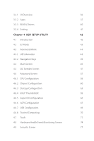
37 3.3.3 BIOS & Drivers 40 3.3.4 Setting 41 Chapter 4 UEFI SETUP UTILITY 42 4.1 Introduction 42 4.2 EZ Mode 43 4.3 Advanced Mode 44 4.3.1 UEFI Menu Bar 44 4.3.2 Navigation Keys 45 4.4 Main Screen 46 4.5 OC Tweaker Screen 47 4.6 Advanced Screen 57 4.6.1 CPU Configuration 58 - ASRock Z370 Pro4 | User Manual - Page 6
4.10 Boot Screen 78 4.11 Exit Screen 81 - ASRock Z370 Pro4 | User Manual - Page 7
may find the latest VGA cards and CPU support list on ASRock's website as well. ASRock website http://www.asrock.com. 1.1 Package Contents • ASRock Z370 Pro4 Motherboard (ATX Form Factor) • ASRock Z370 Pro4 Quick Installation Guide • ASRock Z370 Pro4 Support CD • 2 x Serial ATA (SATA) Data Cables - ASRock Z370 Pro4 | User Manual - Page 8
Intel® K-Series unlocked CPUs • Supports ASRock BCLK Full-range Overclocking Chipset • Intel® Z370 Memory • Dual Channel DDR4 Memory Technology • 4 x DDR4 DIMM Slots • Supports DDR4 4266+(OC)*/4000(OC)/3866(OC)/ 3800(OC)/3733(OC)/3600(OC)/3200(OC)/2933(OC)/ 2800(OC)/2666/2400/2133 non-ECC, un - ASRock Z370 Pro4 | User Manual - Page 9
Z370 Pro4 Graphics Audio * Intel® UHD Graphics Built-in Visuals and the VGA outputs can be supported only with processors which are GPU integrated. • Supports Intel® UHD Graphics Built-in Visuals : Intel® Quick Sync Video with AVC, MVC (S3D) and MPEG-2 Full HW Encode1, Intel® InTruTM 3D, Intel® - ASRock Z370 Pro4 | User Manual - Page 10
Supports Wake-On-LAN • Supports Lightning/ESD Protection • Supports Energy Efficient Ethernet 802.3az • Supports (Supports ESD Protection) • 1 x USB 3.1 Gen1 Type-C Port (Supports /s Connectors, support RAID (RAID Supports Intel® OptaneTM Technology ** Supports NVMe SSD as boot disks ** Supports ASRock - ASRock Z370 Pro4 | User Manual - Page 11
Z370 Pro4 BIOS Feature Hardware Monitor OS * The CPU Fan Connector supports the CPU fan of maximum 1A (12W) fan power. • 2 x Chassis Fan Connectors (4-pin) (Smart Fan Speed Con- trol) • 1 x Chassis Optional/Water Pump Fan Connector (4-pin) (Smart Fan - ASRock Z370 Pro4 | User Manual - Page 12
please visit our website: http://www.asrock.com Please realize that there is a certain risk involved with overclocking, including adjusting the setting in the BIOS, applying Untied Overclocking Technology, or using third-party overclocking tools. Overclocking may affect your system's stability, or - ASRock Z370 Pro4 | User Manual - Page 13
1.3 Motherboard Layout 1 2 Antenna Port ATX12V1 Z370 Pro4 34 CPU_FAN1 5 PS2 Z370 Pro4 13 26 PCIE4 T B2 1 AUDIO CODEC PCIE5 RoHS PCI1 HD_AUDIO1 COM1 1 1 1 TPMS1 CI1 1 CLRMOS1 1 1 USB_5 CT5 CT6 CT7 CT8 USB_3_4 USB_1_2 1 1 CHA_FAN3/W_PUMP CHA_FAN1 SPK_PLED1 1 BIOS - ASRock Z370 Pro4 | User Manual - Page 14
ATX12V1) 2 Chassis Fan Connector (CHA_FAN2) 3 2 x 288-pin DDR4 DIMM Slots (DDR4_A1, DDR4_B1) 4 2 x 288-pin DDR4 DIMM Slots (DDR4_A2, DDR4_B2) 5 CPU Fan Connector (CPU_FAN1) 6 ATX Power Connector (ATXPWR1) 7 USB 3.1 Gen1 Header (USB3_5_6) 8 SATA3 Connector (SATA_5) 9 SATA3 Connector (SATA_4) 10 SATA3 - ASRock Z370 Pro4 | User Manual - Page 15
1.4 I/O Panel 1 2 Z370 Pro4 5 3 4 6 13 12 11 10 9 8 7 No. Description 1 PS/2 Mouse/Keyboard Port 2 D-Sub Port 3 USB 3.1 Gen1 Port (USB3_TA_1) 4 LAN RJ-45 Port* 5 Line In (Light Blue)** 6 Front - ASRock Z370 Pro4 | User Manual - Page 16
** To configure 7.1 CH HD Audio, it is required to use an HD front panel audio module and enable the multichannel audio feature through the audio driver. Please set Speaker Configuration to "7.1 Speaker"in the Realtek HD Audio Manager. Function of the Audio Ports in 7.1-channel Configuration: Port - ASRock Z370 Pro4 | User Manual - Page 17
Z370 Pro4 Chapter 2 Installation This is an ATX form factor motherboard. Before you install the motherboard, study the configuration of your chassis to ensure that the motherboard fits into it. Pre-installation Precautions Take note of the following precautions before you install motherboard - ASRock Z370 Pro4 | User Manual - Page 18
check if the PnP cap is on the socket, if the CPU surface is unclean, or if there are any bent pins in the socket. Do not force to insert the CPU into the socket if above situation is found. Otherwise, the CPU will be seriously damaged. 2. Unplug all power cables before installing - ASRock Z370 Pro4 | User Manual - Page 19
Z370 Pro4 3 4 5 13 English - ASRock Z370 Pro4 | User Manual - Page 20
Please save and replace the cover if the processor is removed. The cover must be placed if you wish to return the motherboard for after service. 14 English - ASRock Z370 Pro4 | User Manual - Page 21
2.2 Installing the CPU Fan and Heatsink Z370 Pro4 1 2 CPU_FAN English 15 - ASRock Z370 Pro4 | User Manual - Page 22
2.3 Installing Memory Modules (DIMM) This motherboard provides four 288-pin DDR4 (Double Data Rate 4) DIMM slots, and supports Dual Channel Memory Technology. 1. For dual channel configuration, you always need to install identical (the same brand, speed, size and chip-type) DDR4 DIMM pairs. 2. - ASRock Z370 Pro4 | User Manual - Page 23
Z370 Pro4 1 2 3 17 English - ASRock Z370 Pro4 | User Manual - Page 24
Slots) There is 1 PCI slot and 5 PCI Express slots on the motherboard. Before installing an expansion card, please make sure that the power supply a better thermal environment, please connect a chassis fan to the motherboard's chassis fan connector (CHA_FAN1, CHA_FAN2 or CHA_FAN3) when using multiple - ASRock Z370 Pro4 | User Manual - Page 25
Z370 Pro4 2.5 Jumpers Setup The illustration shows how jumpers are setup. When the jumper cap is jumper cap after clearing the CMOS. If you need to clear the CMOS when you just finish updating the BIOS, you must boot up the system first, and then shut it down before you do the clear-CMOS action. - ASRock Z370 Pro4 | User Manual - Page 26
place jumper caps over these headers and connectors. Placing jumper caps over the headers and connectors will cause permanent damage to the motherboard. System Panel Header (9-pin PANEL1) (see p.7, No. 14) PLED+ PLEDPWRBTN# GND 1 GND RESET# GND HDLEDHDLED+ Connect the power button, reset button - ASRock Z370 Pro4 | User Manual - Page 27
Z370 Pro4 Power LED and Speaker Header (7-pin SPK_PLED1) (see p.7, No. 15) SPEAKER DUMMY DUMMY disabled. USB_PWR PP+ GND DUMMY 1 GND P+ PUSB_PWR There are two USB 2.0 headers on this motherboard. Each USB 2.0 header can support two ports. 1 GND P+ PUSB_PWR There is one USB 2.0 header on this - ASRock Z370 Pro4 | User Manual - Page 28
1 There is one header on this motherboard. Each USB 3.1 Gen1 header can support two ports. Front Panel Audio Header Audio supports Jack Sensing, but the panel wire on the chassis must support HDA to function correctly. Please follow the instructions in our manual and chassis manual to install - ASRock Z370 Pro4 | User Manual - Page 29
Z370 Pro4 Chassis Fan / Waterpump Fan Connector (4-pin CHA_FAN3/W_ PUMP) (see p.7, No. 16) 1 234 FAN_SPEED_CONTROL CHA_FAN_SPEED FAN_VOLTAGE GND Please connect fan cables to the fan connectors and match the black wire to the ground pin. CPU GND TTXD1 DDCD#1 This motherboard provides an 8-pin ATX - ASRock Z370 Pro4 | User Manual - Page 30
p.7, No. 26) PCICLK FRAME PCIRST# LAD3 +3V LAD0 +3VSB GND GND SMB_CLK_MAIN SMB_DATA_MAIN LAD2 LAD1 GND S_PWRDWN# SERIRQ# GND This motherboard supports CASE OPEN detection feature that detects if the chassis cove has been removed. This feature requires a chassis with chassis intrusion detection - ASRock Z370 Pro4 | User Manual - Page 31
Z370 Pro4 2.7 CrossFireXTM and Quad CrossFireXTM Operation Guide This motherboard supports CrossFireXTM and Quad CrossFireXTM that allows to enable CrossFireXTM. Please refer to AMD graphics card manuals for detailed installation guide. 2.7.1 Installing Two CrossFireXTM-Ready Graphics Cards Step 1 - ASRock Z370 Pro4 | User Manual - Page 32
Step 3 Connect a VGA cable or a DVI cable to the monitor connector or the DVI connector of the graphics card that is inserted to PCIE2 slot. 26 English - ASRock Z370 Pro4 | User Manual - Page 33
Z370 Pro4 2.7.2 Driver Installation and Setup Step 1 Power on your computer and boot previously installed Catalyst drivers prior to installation. Please check AMD's website for AMD driver updates. Step 3 Install the required drivers and CATALYST Control Center then restart your computer. Please - ASRock Z370 Pro4 | User Manual - Page 34
2.8 M.2_SSD (NGFF) Module Installation Guide The M.2, also known as the Next Generation Form Factor (NGFF), is a small size and versatile card edge connector that aims to replace mPCIe and mSATA. The Ultra M.2 Sockets (M2_1 and M2_2) support SATA3 6.0 Gb/s module and M.2 PCI Express module up to - ASRock Z370 Pro4 | User Manual - Page 35
C B A C B A D C B A D NUT2 NUT1 Z370 Pro4 Step 3 Move the standoff based on the module type and length. on the nut to be used. Hand tighten the standoff into the desired nut location on the motherboard. Step 5 Align and gently insert the M.2 (NGFF) SSD module into the M.2 slot. Please - ASRock Z370 Pro4 | User Manual - Page 36
M.2_SSD (NGFF) Module Support List Vendor ADATA ADATA ADATA ADATA ADATA ADATA ADATA ADATA ADATA ADATA Apacer Corsair Crucial Crucial Intel Intel Intel Kingston Kingston Kingston OCZ PATRIOT Plextor - ASRock Z370 Pro4 | User Manual - Page 37
Z370 Pro4 TEAM TEAM Transcend Transcend Transcend V-Color V-Color V-Color V-Color WD WD WDS240G1G0B-00RC30 WDS256G1X0C-00ENX0 (NVME) WDS512G1X0C-00ENX0 (NVME) For the latest updates of M.2_SSD (NFGG) module support list, please visit our website for details: http://www.asrock.com English 31 - ASRock Z370 Pro4 | User Manual - Page 38
does not appear automatically, locate and double click on the file "ASRSETUP.EXE" in the Support CD to display the menu. Drivers Menu The drivers compatible to your system will be auto-detected and listed on the support CD driver page. Please click Install All or follow the order from top to bottom - ASRock Z370 Pro4 | User Manual - Page 39
Z370 Pro4 3.2 A-Tuning A-Tuning is ASRock's multi purpose software suite with a new interface, more new features and improved utilities. 3.2.1 Installing A-Tuning A-Tuning can be downloaded from ASRock Live Update & APP Shop. After the installation, you will find the icon "A-Tuning" on your desktop. - ASRock Z370 Pro4 | User Manual - Page 40
OC Tweaker Configurations for overclocking the system. System Info View information about the system. *The System Browser tab may not appear for certain models. 34 English - ASRock Z370 Pro4 | User Manual - Page 41
Z370 Pro4 FAN-Tastic Tuning Configure up to five different fan speeds using the graph. The fans will automatically shift to the next speed level when the assigned temperature is met. Settings Configure ASRock A-Tuning. Click to select "Auto run at Windows Startup" if you want A-Tuning to be launched - ASRock Z370 Pro4 | User Manual - Page 42
. You can quickly and easily install various apps and support utilities. With ASRock APP Shop, you can optimize your system and keep your motherboard up to date simply with a few clicks. Double-click utility. on your desktop to access ASRock Live Update & APP Shop *You need to be connected to the - ASRock Z370 Pro4 | User Manual - Page 43
Z370 Pro4 3.3.2 Apps When the "Apps" tab is selected, you will see all the available apps on up and down to see more apps listed. You can check the price of the app and whether you have already intalled it or not. - The red icon displays the price or "Free" if the app is free of charge. - The green - ASRock Z370 Pro4 | User Manual - Page 44
Step 3 If you want to install the app, click on the red icon to start downloading. Step 4 When installation completes, you can find the green "Installed" icon appears on the upper right corner. English To uninstall it, simply click on the trash can icon . *The trash icon may not appear for - ASRock Z370 Pro4 | User Manual - Page 45
installed. When there is an available new version for your app, you will find the mark of "New Version" appears below the installed app icon. Z370 Pro4 Step 1 Click on the app icon to see more details. Step 2 Click on the yellow icon to start upgrading. English 39 - ASRock Z370 Pro4 | User Manual - Page 46
recommended or critical updates for the BIOS or drivers. Please update them all soon. Step 1 Please check the item information before update. Click on Step 2 to see more details. Click to select one or more items you want to update. Step 3 Click Update to start the update process. 40 English - ASRock Z370 Pro4 | User Manual - Page 47
Z370 Pro4 3.3.4 Setting In the "Setting" page, you can change the language, select the server location, and determine if you want to automatically run the ASRock Live Update & APP Shop on Windows startup. 41 English - ASRock Z370 Pro4 | User Manual - Page 48
button on the system chassis. You may also restart by turning the system off and then back on. Because the UEFI software is constantly being updated, the following UEFI setup screens and descriptions are for reference purpose only, and they may not exactly match what you see on your screen. 42 - ASRock Z370 Pro4 | User Manual - Page 49
Z370 Pro4 4.2 EZ Mode The EZ Mode screen appears when you enter the BIOS setup program by default. EZ mode is a dashboard which contains multiple readings of the system's current status. You can check the most crucial information of your system, such as CPU speed, DRAM frequency, SATA information, - ASRock Z370 Pro4 | User Manual - Page 50
Mode The Advanced Mode provides more options to configure the BIOS settings. Refer to the following sections for the detailed selections: Main For setting system time/date information OC Tweaker For overclocking configurations Advanced For advanced system configurations Tool Useful tools - ASRock Z370 Pro4 | User Manual - Page 51
Z370 Pro4 4.3.2 Navigation Keys Use < > key or < > key to choose among the selections on the menu bar, and use < > key or < > key to move the cursor up - ASRock Z370 Pro4 | User Manual - Page 52
4.4 Main Screen When you enter the UEFI SETUP UTILITY, the Main screen will appear and display the system overview. My Favorite Display your collection of BIOS items. Press F5 to add/remove your favorite items. 46 English - ASRock Z370 Pro4 | User Manual - Page 53
4.5 OC Tweaker Screen In the OC Tweaker screen, you can set up overclocking features. Z370 Pro4 Because the UEFI software is constantly being updated, the following UEFI setup screens and descriptions are for reference purpose only, and they may not exactly match what you see on your screen. CPU - ASRock Z370 Pro4 | User Manual - Page 54
overclocking. Boot Performance Mode Default is Max Non-Turbo performance mode. It will keep cpu Flex-ratio till OS handoff. Max Battery mode will set CPU be aware of the BCLK frequency when calculating the CPU V/F curves. This is ideal for BCLK OC to avoid high voltage overrides. Ring to Core Ratio - ASRock Z370 Pro4 | User Manual - Page 55
Z370 Pro4 Intel Speed Shift Technology Enable/Disable Intel Speed Shift Technology support. Enabling will expose the CPPC v2 interface to allow for hardware controlled P-sates. Long Duration Power Limit Configure Package Power Limit 1 in watts. When the limit is exceeded, the CPU ratio will be - ASRock Z370 Pro4 | User Manual - Page 56
DRAM Frequency If [Auto] is selected, the motherboard will detect the memory module(s) inserted and assign the appropriate frequency automatically. Primary Timing CAS# Latency (tCL) The time between sending a column address to the - ASRock Z370 Pro4 | User Manual - Page 57
Z370 Pro4 Write to Read Delay (tWTR_L) The number of clocks between the last valid write operation and the next read command to the same internal bank. - ASRock Z370 Pro4 | User Manual - Page 58
tRDWR_dg Configure between module read to write delay. tRDWR_dr Configure between module read to write delay. tRDWR_dd Configure between module read to write delay. tWRRD_sg Configure between module write to read delay. tWRRD_dg Configure between module write to read delay. tWRRD_dr Configure - ASRock Z370 Pro4 | User Manual - Page 59
twRPDEN. OREF_RI Configure OREF_RI. tREFIx9 Configure tREFIx9. txSDLL Configure txSDLL. txs_offset Configure txs_offset. tZQOPER Configure tZQOPER. tMOD Configure tMOD. ZQCS_period Configure ZQCS_period. tZQCS Configure tZQCS. Z370 Pro4 53 English - ASRock Z370 Pro4 | User Manual - Page 60
RTL Init Value Configure round trip latency init value for round trip latency training. IO-L Init Value Configure IO latency init value for IO latency traning. RTL (CH A) Configure round trip latency for channel A. RTL (CH B) Configure round trip latency for channel B. IO-L (CH A) Configure IO - ASRock Z370 Pro4 | User Manual - Page 61
Z370 Pro4 ODT PARK (CH B) Configure the memory on die termination resistors' PARK for channel B. ODT NOM (CH A) Use this to change ODT (CH A) Auto/Manual settings. The default is [Auto]. ODT NOM (CH B) Use this to change ODT (CH B) Auto/Manual settings. The default is [Auto]. MRC Fast Boot Enable - ASRock Z370 Pro4 | User Manual - Page 62
to find the best value for user's own processor. Memory Controller PLL Voltage Default is 0.900V. Each step is 0.015V. Adding 9 -15 steps will help CPU PLL to lock internal clock during High frequency under Ln2 cooling. For example: 1.020V 1.125V will be proper value. Bu the voltage level will be - ASRock Z370 Pro4 | User Manual - Page 63
Z370 Pro4 4.6 Advanced Screen In this section, you may set the configurations for the following items: CPU Configuration, the resolution will be set to 1920 x 1080 if the monitor supports Full HD resolution. If the monitor does not support Full HD resolution, then the resolution will be set to 1024 x - ASRock Z370 Pro4 | User Manual - Page 64
Configuration Active Processor Cores Select the number of cores to enable in each processor package. CPU C States Support Enable CPU C States Support for power saving. It is recommended to keep C3, C6 and C7 all enabled for better power saving. Enhanced Halt State (C1E) Enable Enhanced Halt - ASRock Z370 Pro4 | User Manual - Page 65
Z370 Pro4 CFG Lock This item allows you to disable or enable the CFG Lock. CPU Thermal Throttling Enable CPU internal thermal control mechanisms to keep the CPU from overheating. Intel Virtualization Technology Intel Virtualization Technology allows a platform to run multiple operating systems and - ASRock Z370 Pro4 | User Manual - Page 66
to be decoded in Above 4G Address Space (only if the system supports 64 bit PCI decoding). VT-d Intel® Virtualization Technology for Directed I/O virtual machine monitor better utilize hardware by improving application compatibility and reliability, and providing additional levels of manageability, - ASRock Z370 Pro4 | User Manual - Page 67
Z370 Pro4 Select the link speed for PCIE2. PCIE3 Link Speed Select the link speed for PCIE3. PCIE4 Link Speed Select the link speed for PCIE4. PCIE5 Link Speed Select the link speed for PCIE5. PCI Express Native Control Select Enable for enhanced PCI Express power saving in OS. PCIE ASPM Support - ASRock Z370 Pro4 | User Manual - Page 68
HD audio and automatically disable it when a sound card is installed. Front Panel Enable/disable front panel HD audio. WAN Radio Enable/disable the WiFi module's connectivity. Deep Sleep Configure deep sleep mode for power saving when the computer is shut down. Restore on AC/Power Loss Select the - ASRock Z370 Pro4 | User Manual - Page 69
4.6.3 Storage Configuration Z370 Pro4 SATA Controller(s) Enable/disable the SATA controllers. SATA Controller Speed Indicates the maximum speed the SATA controller can support. SATA Mode Selection AHCI: Supports new features that improve performance. Intel RST Premium (RAID): Combine multiple disk - ASRock Z370 Pro4 | User Manual - Page 70
Hard Disk S.M.A.R.T. S.M.A.R.T stands for Self-Monitoring, Analysis, and Reporting Technology. It is a monitoring system for computer hard disk drives to detect and report on various indicators of reliability. 64 English - ASRock Z370 Pro4 | User Manual - Page 71
4.6.4 Intel® Thunderbolt Z370 Pro4 Intel® Thunderbolt Technology Enable or disable the Intel® Thunderbolt™ function. Security Level This item allows you to choose a security level for the Thunderbolt ports. AR AIC Support Enable or disable to support AR AIC card. TBT Host Router Enable the host - ASRock Z370 Pro4 | User Manual - Page 72
4.6.5 Super IO Configuration Serial Port Enable or disable the Serial port. Serial Port Address Select the address of the Serial port. PS2 Y-Cable Enable the PS2 Y-Cable or set this option to Auto. 66 English - ASRock Z370 Pro4 | User Manual - Page 73
4.6.6 ACPI Configuration Z370 Pro4 Suspend to RAM Select disable for ACPI suspend type S1. It is recommended to select auto for ACPI S3 power saving. ACPI HEPT Table Enable the High Precision - ASRock Z370 Pro4 | User Manual - Page 74
USB Mouse Power On Allow the system to be waked up by an USB mouse. 68 English - ASRock Z370 Pro4 | User Manual - Page 75
4.6.7 USB Configuration Z370 Pro4 Legacy USB Support Enable or disable Legacy OS Support for USB 2.0 devices. If you encounter USB compatibility issues it is recommended to disable legacy USB support. Select UEFI Setup Only to support USB devices under the UEFI setup and Windows/Linux operating - ASRock Z370 Pro4 | User Manual - Page 76
4.6.8 Trusted Computing Security Device Support Enable or disable BIOS support for security device. 70 English - ASRock Z370 Pro4 | User Manual - Page 77
4.7 Tools Z370 Pro4 UEFI Tech Service Contact ASRock Tech Service if you are having trouble with your PC. Please setup network configuration before using UEFI Tech Service. Easy RAID Installer Easy RAID Installer helps you to copy the RAID driver from the support CD to your USB storage device. - ASRock Z370 Pro4 | User Manual - Page 78
your UEFI. Internet Flash - DHCP (Auto IP), Auto ASRock Internet Flash downloads and updates the latest UEFI firmware version from our servers for you. Please setup network configuration before using Internet Flash. *For BIOS backup and recovery purpose, it is recommended to plug in your USB pen - ASRock Z370 Pro4 | User Manual - Page 79
Z370 Pro4 Internet Setting Enable or disable sound effects in the setup utility. UEFI Download Server Select a server to download the UEFI firmware. 73 English - ASRock Z370 Pro4 | User Manual - Page 80
4.8 Hardware Health Event Monitoring Screen This section allows you to monitor the status of the hardware on your system, including the parameters of the CPU temperature, motherboard temperature, fan speed and voltage. Fan Tuning Measure Fan Min Duty Cycle. Fan-Tastic Tuning Select a fan mode for - ASRock Z370 Pro4 | User Manual - Page 81
Z370 Pro4 assign a respective fan speed for each Chassis Fan 2 Setting Select a fan mode for Fans, or choose Customize to set 5 CPU temperatures and assign a respective fan speed for each temperature. Chassis Fan 2 Temp Source automatically shuts down when the motherboard is overheated. 75 English - ASRock Z370 Pro4 | User Manual - Page 82
Case Open Feature Enable or disable Case Open Feature to detect whether the chassis cover has been removed. 76 English - ASRock Z370 Pro4 | User Manual - Page 83
Z370 Pro4 4.9 Security Screen In this section you may set or change the supervisor/ blank and press enter to remove the password. Secure Boot Use this item to enable or disable support for Secure Boot. Intel(R) Platform Trust Technology Enable/disable Intel PTT in ME. Disable this option to use - ASRock Z370 Pro4 | User Manual - Page 84
devices. Fast Boot Fast Boot minimizes your computer's boot time. In fast mode you may not boot from an USB storage device. The VBIOS must support UEFI GOP if you are using an external graphics card. Please notice that Ultra Fast mode will boot so fast that the only way to - ASRock Z370 Pro4 | User Manual - Page 85
Z370 Pro4 Setup Prompt Timeout Configure the number of seconds to wait for the setup hot key. Bootup Num-Lock Select whether Failure Guard Message If the computer fails to boot for a number of times the system automatically restores the default settings. CSM (Compatibility Support Module) 79 English - ASRock Z370 Pro4 | User Manual - Page 86
CSM Enable to launch the Compatibility Support Module. Please do not disable unless you're running a WHCK test. Launch PXE OpROM Policy Select UEFI only to run those that support UEFI option ROM only. Select Legacy only to run those that support legacy option ROM only. Select Do not launch to not - ASRock Z370 Pro4 | User Manual - Page 87
4.11 Exit Screen Z370 Pro4 Save Changes and Exit When you select this option the following message, "Save configuration changes and exit setup?" will pop out. Select [OK] to save - ASRock Z370 Pro4 | User Manual - Page 88
or want to know more about ASRock, you're welcome to visit ASRock's website at http://www.asrock.com; or you may contact your dealer for further information. For technical questions, please submit a support request form at http://www.asrock.com/support/tsd.asp ASRock Incorporation 2F., No.37, Sec - ASRock Z370 Pro4 | User Manual - Page 89
FCC Part 2 Section 2.1077(a) Responsible Party Name: ASRock Incorporation Address: 13848 Magnolia Ave, Chino, CA91710 Phone/Fax No: +1-909-590-8308/+1-909-590-1026 hereby declares that the product Product Name : Motherboard Model Number : Z370 Pro4 Conforms to the following speci cations: FCC Part15 - ASRock Z370 Pro4 | User Manual - Page 90
EU Declaration of Conformity For the following equipment: Motherboard (Product Name) Z370 Pro4 / ASRock (Model Designation / Trade Name) ASRock Incorporation (Manufacturer Name) 2F., No.37, Sec. 2, Jhongyang S. Rd., Beitou District, Taipei City 112, Taiwan (R.O.C.) (Manufacturer Address) ڛEMC
-
 1
1 -
 2
2 -
 3
3 -
 4
4 -
 5
5 -
 6
6 -
 7
7 -
8
-
9
-
10
-
11
-
12
-
13
-
14
-
15
-
16
-
17
-
18
-
19
-
20
-
21
-
22
-
23
-
24
-
25
-
26
-
27
-
28
-
29
-
30
-
31
-
32
-
33
-
34
-
35
-
36
-
37
-
38
-
39
-
40
-
41
-
42
-
43
-
44
-
45
-
46
-
47
-
48
-
49
-
50
-
51
-
52
-
53
-
54
-
55
-
56
-
57
-
58
-
59
-
60
-
61
-
62
-
63
-
64
-
65
-
66
-
67
-
68
-
69
-
70
-
71
-
72
-
73
-
74
-
75
-
76
-
77
-
78
-
79
-
80
-
81
-
82
-
83
-
84
-
85
-
86
-
87
-
88
-
89
-
90
 |
 |
