ASRock Z390 Extreme4 Quick Installation Guide
ASRock Z390 Extreme4 Manual
 |
View all ASRock Z390 Extreme4 manuals
Add to My Manuals
Save this manual to your list of manuals |
ASRock Z390 Extreme4 manual content summary:
- ASRock Z390 Extreme4 | Quick Installation Guide - Page 1
change without notice, and should not be constructed as a commitment by ASRock. ASRock assumes no responsibility for any errors or omissions that may appear in CALIFORNIA, USA ONLY The Lithium battery adopted on this motherboard contains Perchlorate, a toxic substance controlled in Perchlorate Best - ASRock Z390 Extreme4 | Quick Installation Guide - Page 2
if the goods fail to be of acceptable quality and the failure does not amount to a major failure. If you require assistance please call ASRock Tel : +886-2-28965588 ext.123 (Standard International call charges apply) The terms HDMI® and HDMI High-Definition Multimedia Interface, and the HDMI logo - ASRock Z390 Extreme4 | Quick Installation Guide - Page 3
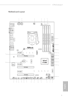
Motherboard Layout 1 2 ATX12V1 ATX12V2 Z390 Extreme4 3 4 56 CPU_FAN1 CPU_FAN2/WP PS2 Keyboard /Mouse USB 3.1 Gen1 Bottom: MIC IN Z390 EXTREME4 CHA_FAN1/WP Ultra M.2 PCIe Gen3 x4 LAN 1 9 USB3_7_8 M2_1 PCIE1 CT4 CT3 CT2 CT1 30 RoHS PCIE2 LAN M2_3 CMOS Battery 29 CLRMOS1 - ASRock Z390 Extreme4 | Quick Installation Guide - Page 4
AIC Connector (TB1) 25 RGB LED Header (RGB_LED2) 26 RGB LED Header (RGB_LED1) 27 Addressable LED Header (ADDR_LED1) 28 Front Panel Audio Header (HD_AUDIO1) 29 Clear CMOS Jumper (CLRMOS1) 30 Chassis/Water Pump Fan Connector (CHA_FAN1/WP) 2 English - ASRock Z390 Extreme4 | Quick Installation Guide - Page 5
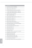
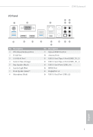
I/O Panel 1 2 Z390 Extreme4 46 3 57 16 15 14 No. Description 1 PS/2 Mouse/Keyboard Port 2 D-Sub Port 3 LAN RJ-45 Port* 4 Central / Bass (Orange) 5 Rear Speaker (Black) 6 Line In ( - ASRock Z390 Extreme4 | Quick Installation Guide - Page 6
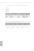
* There are two LEDs on each LAN port. Please refer to the table below for the LAN port LED indications. ACT/LINK LED SPEED LED LAN Port Activity / Link LED Status Off Blinking On Description No Link Data Activity Link Speed LED Status Off Orange Green Description 10Mbps connection 100Mbps - ASRock Z390 Extreme4 | Quick Installation Guide - Page 7
latest VGA cards and CPU support list on ASRock's website as well. ASRock website http://www.asrock.com. 1.1 Package Contents • ASRock Z390 Extreme4 Motherboard (ATX Form Factor) • ASRock Z390 Extreme4 Quick Installation Guide • ASRock Z390 Extreme4 Support CD • 1 x I/O Panel Shield • 4 x Serial ATA - ASRock Z390 Extreme4 | Quick Installation Guide - Page 8
Processors (Socket 1151) • Digi Power design • 12 Power Phase design • Supports Intel® Turbo Boost 2.0 Technology • Supports Intel® K-Series unlocked CPUs • Supports ASRock BCLK Full-range Overclocking Chipset • Intel® Z390 Memory • Dual Channel DDR4 Memory Technology • 4 x DDR4 DIMM Slots - ASRock Z390 Extreme4 | Quick Installation Guide - Page 9
Z390 Extreme4 Graphics Audio • Intel® UHD Graphics Built-in Visuals and the VGA outputs can be supported only with processors which are GPU integrated. • Supports Intel® UHD Graphics Built-in Visuals : Intel® Quick Sync Video with AVC, MVC (S3D) and MPEG-2 Full HW Encode1, Intel® InTruTM 3D, Intel - ASRock Z390 Extreme4 | Quick Installation Guide - Page 10
x Optical SPDIF Out Port • 1 x USB 3.1 Gen2 Type-A Port (10 Gb/s) (ReDriver) (Supports ESD Protection) • 1 x USB 3.1 Gen2 Type-C Port (10 Gb/s) (ReDriver) (Supports ESD Protection) • 4 x USB 3.1 Gen1 Ports (Intel® Z390) (Supports ESD Protection) • 1 x RJ-45 LAN Port with LED (ACT/LINK LED and SPEED - ASRock Z390 Extreme4 | Quick Installation Guide - Page 11
Z390 Extreme4 * M2_1, SATA3_0 and SATA3_1 share lanes. If either one of them is in use, the others will be disabled. * M2_2, SATA3_4 and SATA3_5 share lanes. If either one of them is in use, the others will be disabled. • 1 x Ultra M.2 Socket (M2_1), supports M Key type 2230/2242/2260/2280 M.2 - ASRock Z390 Extreme4 | Quick Installation Guide - Page 12
Gold Audio Connector) • 1 x Thunderbolt AIC Connector (5-pin) • 2 x USB 2.0 Headers (Support 4 USB 2.0 ports) (Intel® Z390) (Supports ESD Protection) • 2 x USB 3.1 Gen1 Headers (Support 4 USB 3.1 Gen1 ports) (ASMedia ASM1074 hub) (Supports ESD Protection) • 1 x Front Panel Type C USB 3.1 Gen1 Header - ASRock Z390 Extreme4 | Quick Installation Guide - Page 13
Z390 Extreme4 * For detailed product information, please visit our website: http://www.asrock.com Please realize that there is a certain risk involved with overclocking, including adjusting the setting in the BIOS, applying Untied Overclocking Technology, or using third-party overclocking tools. - ASRock Z390 Extreme4 | Quick Installation Guide - Page 14
to ensure that the motherboard fits into it. Pre-installation Precautions Take note of the following precautions before you install motherboard components or change any motherboard settings. • Make sure to unplug the power cord before installing or removing the motherboard components. Failure to do - ASRock Z390 Extreme4 | Quick Installation Guide - Page 15
Z390 Extreme4 2.1 Installing the CPU 1. Before you insert the 1151-Pin CPU into the socket, please check if the PnP cap is on the CPU into the socket if above situation is found. Otherwise, the CPU will be seriously damaged. 2. Unplug all power cables before installing the CPU. 1 A B 2 13 English - ASRock Z390 Extreme4 | Quick Installation Guide - Page 16
4 5 14 3 English - ASRock Z390 Extreme4 | Quick Installation Guide - Page 17
Z390 Extreme4 Please save and replace the cover if the processor is removed. The cover must be placed if you wish to return the motherboard for after service. 15 English - ASRock Z390 Extreme4 | Quick Installation Guide - Page 18
2.2 Installing the CPU Fan and Heatsink 1 2 CPU_FAN English 16 - ASRock Z390 Extreme4 | Quick Installation Guide - Page 19
Z390 Extreme4 2.3 Installing Memory Modules (DIMM) This motherboard provides four 288-pin DDR4 (Double Data Rate 4) DIMM slots, and supports Dual Channel Memory Technology. 1. For dual channel configuration, you always need to install identical (the same brand, speed, size and chip-type) DDR4 DIMM - ASRock Z390 Extreme4 | Quick Installation Guide - Page 20
1 2 3 18 English - ASRock Z390 Extreme4 | Quick Installation Guide - Page 21
Z390 Extreme4 2.4 Expansion Slots (PCI Express Slots) There are 6 PCI Express slots on the motherboard. Before installing an expansion card, please make sure that the power supply is switched off or the power cord is unplugged. Please read the documentation of the - ASRock Z390 Extreme4 | Quick Installation Guide - Page 22
no jumper cap is placed on the pins, the jumper is "Open". Clear CMOS Jumper (CLRCMOS1) (see p.1, No. 29) 2-pin Jumper Short: Clear CMOS Open: Default CLRCMOS1 allows you to clear the data in CMOS. The data in CMOS includes system setup information such as system password, date, time, and system - ASRock Z390 Extreme4 | Quick Installation Guide - Page 23
Z390 Extreme4 2.6 Onboard Headers and Connectors Onboard headers and connectors are NOT jumpers. Do NOT place jumper caps over these headers and connectors. Placing jumper caps over the headers and connectors will cause permanent damage to the motherboard. System Panel Header (9-pin PANEL1) (see - ASRock Z390 Extreme4 | Quick Installation Guide - Page 24
These eight SATA3 connectors support SATA data cables for Z390 SATA ports (SATA3_0) for your SSDs. USB 2.0 Headers (9-pin USB_1_2) (see p.1, No. 20) (9-pin USB_3_4) (see p.1, No. 19) USB_PWR PP+ GND DUMMY 1 GND P+ PUSB_PWR There are two headers on this motherboard. Each USB 2.0 header can support - ASRock Z390 Extreme4 | Quick Installation Guide - Page 25
Z390 Extreme4 USB 3.1 Gen1 Headers (19- two headers on this motherboard. Each USB 3.1 Gen1 header can support two ports. Front supports Jack Sensing, but the panel wire on the chassis must support HDA to function correctly. Please follow the instructions in our manual and chassis manual to install - ASRock Z390 Extreme4 | Quick Installation Guide - Page 26
CPU_FAN_SPEED (4-pin CPU_FAN2/WP) FAN_VOLTAGE GND (see p.1, No. 4) This motherboard 4 provides a 4-Pin water 3 2 cooling CPU fan 1 connector Connector (24-pin ATXPWR1) (see p.1, No. 7) 12 24 1 13 This motherboard provides a 24-pin ATX power connector. To use a 20-pin ATX power supply, please - ASRock Z390 Extreme4 | Quick Installation Guide - Page 27
Z390 Extreme4 LAD0 +3V LAD3 PCIRST # FRAM E PCICLK 8 5 4 1 This motherboard provides an 8-pin ATX 12V power connector. To use a 4-pin connector via the GPIO cable. *Please install the Thunderbolt™ AIC card to PCIE6 header supports a serial port module. This connector supports Trusted Platform - ASRock Z390 Extreme4 | Quick Installation Guide - Page 28
cable which allows users to choose from various LED lighting effects. Caution: Never install the Addressable LED cable in the wrong orientation; otherwise, the cable may be damaged. *Please refer to page 34 for further instructions on this header. Please connect the OC switch and OC LED indicator on - ASRock Z390 Extreme4 | Quick Installation Guide - Page 29
Z390 Extreme4 2.7 M.2 WiFi/BT Module and Intel® CNVi (Integrated WiFi/BT) Installation Guide The M.2, also known as the Next Generation Form Factor (NGFF), is a small size and versatile card edge connector that aims to replace mPCIe and mSATA. The M.2 Socket (Key E) supports type 2230 WiFi/BT module - ASRock Z390 Extreme4 | Quick Installation Guide - Page 30
A A 20o A Step 3 Gently insert the WiFi/BT module or Intel® CNVi (Integrated WiFi/ BT) into the M.2 slot. Please be aware that the module only fits in one orientation. Step 4 Tighten the screw with a screwdriver to secure the module - ASRock Z390 Extreme4 | Quick Installation Guide - Page 31
Z390 Extreme4 2.8 M.2_SSD (NGFF) Module Installation Guide (M2_1 and M2_2) The M.2, also known as the Next Generation Form Factor (NGFF), is a small size and versatile card edge connector that aims to replace mPCIe and mSATA. The Ultra M.2 Sockets (M2_1 and M2_2) support SATA3 6.0 Gb/s module and - ASRock Z390 Extreme4 | Quick Installation Guide - Page 32
1 Step 3 Before installing a M.2 (NGFF) SSD module, please loosen the screws to 2 remove the M.2 heatsink. 1 E D C B A Step4 Align and gently insert the M.2 (NGFF) SSD module into the M.2 slot. Please be - ASRock Z390 Extreme4 | Quick Installation Guide - Page 33
M.2_SSD (NGFF) Module Support List Vendor ADATA ADATA ADATA ADATA ADATA ADATA ADATA ADATA ADATA ADATA SM951 (MZHPV256HDGL) SM951 (MZHPV512HDGL) SM951 (NVME) XP941-512G (MZHPU512HCGL) SD6PP4M-128G SD6PP4M-256G TM4PS4128GMC105 TM4PS4256GMC105 TM8PS4128GMC105 TM8PS4256GMC105 Z390 Extreme4 31 English - ASRock Z390 Extreme4 | Quick Installation Guide - Page 34
VSM100-240G-2280 VLM100-240G-2280B-RD WDS100T1B0B-00AS40 WDS240G1G0B-00RC30 WDS256G1X0C-00ENX0 (NVME) WDS512G1X0C-00ENX0 (NVME) For the latest updates of M.2_SSD (NFGG) module support list, please visit our website for details: http://www.asrock.com English 32 - ASRock Z390 Extreme4 | Quick Installation Guide - Page 35
Z390 Extreme4 2.9 ASRock Polychrome RGB ASRock Polychrome RGB is a lighting control utility specifically designed for unique individuals with sophisticated tastes to build their own stylish colorful lighting system. Simply by connecting - ASRock Z390 Extreme4 | Quick Installation Guide - Page 36
motherboard. ADDR_LED1 1 GND DO_ADDR VOUT 1 1. Never install the RGB LED cable in the wrong orientation; otherwise, the cable may be damaged. 2. Before installing to motherboard components. 1. Please note that the RGB LED strips do not come with the package. 2. The RGB LED header supports WS2812B - ASRock Z390 Extreme4 | Quick Installation Guide - Page 37
Z390 Extreme4 ASRock Polychrome RGB Utility Now you can adjust the RGB LED color through the ASRock Polychrome RGB Utility. Download this utility from the ASRock Live Update & APP Shop and start coloring your PC style your way! Drag the tab to customize your preference. Toggle on/off the RGB LED - ASRock Z390 Extreme4 | Quick Installation Guide - Page 38
VGA-Karten und Prozessoren auf der ASRock-Webseite: ASRock-Webseite http://www.asrock.com. 1.1 Lieferumfang • ASRock Z390 Extreme4-Motherboard (ATX-Formfaktor) • ASRock Z390 Extreme4-Schnellinstallationsanleitung • ASRock Z390 Extreme4-Support-CD • 1 x E/A-Blendenabschirmung • 4 x Serial-ATA-(SATA - ASRock Z390 Extreme4 | Quick Installation Guide - Page 39
Z390 Extreme4 1.2 Technische Daten Plattform • ATX-Formfaktor Prozessor • Unterstützt Intel® CoreTM- mit freiem Multiplikator der Intel® K-Serie • Unterstützt ASRock BCLK-Übertaktung (voller Bereich) Chipsatz • Intel® Z390 Speicher • Dualkanal-DDR4-Speichertechnologie • 4 x DDR4-DIMM - ASRock Z390 Extreme4 | Quick Installation Guide - Page 40
integrierte Intel® UHD Graphics-Visualisierung: Intel® Quick Sync Video mit AVC, MVC (S3D) und MPEG-2 Full HW Encode1, Intel® InTruTM 3D, Intel® Clear Video HD Technology, Intel® InsiderTM, Intel® UHD Graphics • DirectX 12 • HWA encodieren/decodieren: AVC/H.264, HEVC/H.265 8 bit, HEVC/H.265 10 bit - ASRock Z390 Extreme4 | Quick Installation Guide - Page 41
Z390 Extreme4 - Direct Drive Technology - PCB-isolierte Abschirmung - Impedanzerkennung am vorderen Ausgang - (ReDriver) (unterstützt Schutz gegen elektrostatische Entladung) • 4 x USB-3.1 Gen1-Ports (Intel® Z390) (unterstützt Schutz gegen elektrostatische Entladung) • 1 x RJ-45-LAN-Port mit LED ( - ASRock Z390 Extreme4 | Quick Installation Guide - Page 42
-Modul bis Gen. 3 x 4 (32 Gb/s)** ** Unterstützt Intel® OptaneTM-Technologie ** Unterstützt NVMe-SSD als Bootplatte ** Unterstützt ASRock U.2-Kit • 1 x COM-Anschluss-Stiftleiste • 1 x TPM-Stiftleiste • 1 x Betrieb-LED- und Lautsprecher-Stiftleiste • 2 x RGB-LED-Stiftleisten * Unterstützt insgesamt - ASRock Z390 Extreme4 | Quick Installation Guide - Page 43
Z390 Extreme4 BIOS-Funktion Hardwareüberwachung Betriebssystem Zertifizierungen • 1 x 4-poliger 12-V-Netzanschluss (hochdichter Netzanschluss) • 1 x Audioanschluss an der Frontblende (15μ goldene Audioan- schluss) • 1 x Thunderbolt Erweiterungskartenanschluss (5-polig) • 2 x USB 2.0-Stiftleisten ( - ASRock Z390 Extreme4 | Quick Installation Guide - Page 44
Detaillierte Produktinformationen finden Sie auf unserer Webseite: http://www.asrock.com Bitte beachten Sie, dass mit einer Übertaktung, zu der die Anpassung von BIOS-Einstellungen, die Anwendung der Untied Overclocking Technology oder die Nutzung von Übertaktungswerkzeugen von Drittanbietern zählen - ASRock Z390 Extreme4 | Quick Installation Guide - Page 45
Z390 Extreme4 1.3 Jumpereinstellung Die Abbildung zeigt, wie die Jumper eingestellt werden. Wenn die Jumper-Kappe auf den Kontakten angebracht ist, ist der Jumper „kurzgeschlossen". Wenn keine Jumper-Kappe auf den Kontakten angebracht ist, ist der Jumper „offen". CMOS-löschen-Jumper (CLRCMOS1) ( - ASRock Z390 Extreme4 | Quick Installation Guide - Page 46
diesen Stiftleisten und Anschlüssen an. Durch Anbringen von Jumper-Kappen an diesen Stiftleisten und Anschlüssen können Sie das Motherboard dauerhaft beschädigen. Systemblende-Stiftleiste (9-polig, PANEL1) (siehe S. 1, Nr. 17) PLED+ PLEDPWRBTN# GND 1 GND RESET# GND HDLEDHDLED+ Verbinden Sie Ein - ASRock Z390 Extreme4 | Quick Installation Guide - Page 47
Z390 Extreme4 Betrieb-LED- und Lautsprecher-Stiftleiste (7-polig, SPK_PLED1) (siehe S. 1, Nr. 18) Serial-ATA-III-Anschlüsse ( Nr. 19) USB_PWR PP+ GND DUMMY 1 GND P+ PUSB_PWR Es gibt zwei Stiftleisten an diesem Motherboard. Jede USB 2.0-Stiftleiste kann zwei Ports unterstützen. Deutsch 45 - ASRock Z390 Extreme4 | Quick Installation Guide - Page 48
(26-polig, USB31_TC_2) (siehe S. 1, Nr. 10) Es gibt eine Type-C-USB-3.1 Gen1-Stiftleiste für die Frontblende an diesem Motherboard. Diese Stiftleiste dient dem Anschluss eines USB-3.1 Gen1-Moduls für zusätzliche USB-3.1 Gen1Ports. Audiostiftleiste (Frontblende) (9-polig, HD_AUDIO1) (siehe - ASRock Z390 Extreme4 | Quick Installation Guide - Page 49
Z390 Extreme4 Gehäuse-/Wasserpumpen-Lüfteranschlusse (4-polig, CHA_FAN1/WP) (siehe S. 1, Nr. 30) (4-polig, CHA_FAN2/ Netzanschluss (24-polig, ATXPWR1) (siehe S. 1, Nr. 7) 12 24 1 13 Dieses Motherboard bietet einen 24-poligen ATX-Netzanschluss. Bitte schließen Sie es zur Nutzung eines 20-poligen - ASRock Z390 Extreme4 | Quick Installation Guide - Page 50
Nr. 1) ATX-12-V-Netzanschluss (4-polig, ATX12V2) (siehe S. 1, Nr. 2) ThunderboltErweiterungskarten anschlüsse (5-polig, TB1) (siehe S. 1, Nr. 24) 1 8 5 Dieses Motherboard bietet ei- nen 8-poligen ATX-12-V-Net- 4 1 zanschluss. Bitte schließen Sie es zur Nutzung eines 4-poligen ATX-Netzteils - ASRock Z390 Extreme4 | Quick Installation Guide - Page 51
Z390 Extreme4 RGB-LED-Stiftleisten (4-polig, RGB_LED1) (siehe S. 1, Nr. 26) (4-polig, RGB_LED2) (siehe S. 1, Nr. 25) 1 12V G R B Adressierbare-LED-Stiftleiste (3-polig, ADDR_LED1) (siehe S. 1, Nr. 27) 1 GND DO_ADDR VOUT - ASRock Z390 Extreme4 | Quick Installation Guide - Page 52
sur le site Internet de ASRock. Site Internet ASRock http://www.asrock.com. 1.1 Contenu de l'emballage • Carte mère ASRock Z390 Extreme4 (facteur de forme ATX) • Guide d'installation rapide ASRock Z390 Extreme4 • CD d'assistance ASRock Z390 Extreme4 • 1 x panneau de protection E/S • 4 x câbles de - ASRock Z390 Extreme4 | Quick Installation Guide - Page 53
Z390 Extreme4 1.2 Spé rie K Intel® • Prend en charge l'overclocking ASRock BCLK Full-range Chipset • Intel® Z390 Mémoire • Technologie mémoire double canal DDR4 socket M.2 (Touche E), prend en charge les modules WiFi/ BT type 2230 et Intel® CNVi (WiFi/BT intégré) • Contact doré 15μ dans fente - ASRock Z390 Extreme4 | Quick Installation Guide - Page 54
la technologie Intel® UHD Graphics Builtin Visuals : Intel® Quick Sync Video avec AVC, MVC (S3D) et MPEG-2 Full HW Encode1, Intel® InTruTM 3D, Intel® Clear Video HD Technology, Intel® InsiderTM, Intel® UHD Graphics • DirectX 12 • Codage/Décodage HWA : AVC/H.264, HEVC/H.265 8 bits, HEVC/H.265 10 bits - ASRock Z390 Extreme4 | Quick Installation Guide - Page 55
Z390 Extreme4 - Technologie Direct Drive - Blindage isolant PCB - Détection d'impédance sur 10 Go/s) (ReDriver) (Protection contre les décharges électrostatiques) • 4 x ports USB 3.1 Gen1 (Intel® Z390) (Protection contre les décharges électrostatiques) • 1 x port RJ-45 LAN avec LED (LED ACT/LIEN et - ASRock Z390 Extreme4 | Quick Installation Guide - Page 56
Go/s)** ** Prend en charge Intel® OptaneTM Technology ** Prend en charge les SSD NVMe comme disques de démarrage ** Prend en charge le kit ASRock U.2 • 1 x embase pour port COM • 1 x embase TPM • 1 x prise DEL d'alimentation et haut-parleur • 2 x embase LED RVB * Prend en charge les rubans LED jusqu - ASRock Z390 Extreme4 | Quick Installation Guide - Page 57
Z390 Extreme4 Caractéristiques du BIOS • 1 x connecteur d'alimentation 12 V 4 broches (connecteur d'alimentation haute densité) • 1 x Connecteur audio panneau avant (15μ Connecteur audio or) • 1 x connecteur Thunderbolt AIC (5 broches) • 2 x embases - ASRock Z390 Extreme4 | Quick Installation Guide - Page 58
, veuillez visiter notre site : http://www.asrock.com Il est important de signaler que l'overclocking présente certains risques, incluant des modifications du BIOS, l'application d'une technologie d'overclocking déliée et l'utilisation d'outils d'overclocking développés par des tiers. La stabilit - ASRock Z390 Extreme4 | Quick Installation Guide - Page 59
est « court-circuité ». Si le capuchon du cavalier n'est pas installé sur les broches, le cavalier est « ouvert ». Cavalier Clear CMOS (CLRCMOS1) Cavalier (jumper) à 2 broches (voir p.1, No. 29) Court-circuité : Fonction Clear CMOS Ouvert : Par défaut CLRCMOS1 vous permet d'effacer les donnés de - ASRock Z390 Extreme4 | Quick Installation Guide - Page 60
1.4 Embases et connecteurs de la carte mère Les embases et connecteurs situés sur la carte NE SONT PAS des cavaliers. Ne placez JAMAIS de capuchons de cavaliers sur ces embases ou connecteurs. Placer un capuchon de cavalier sur ces embases ou connecteurs endommagera irrémédiablement votre carte mère - ASRock Z390 Extreme4 | Quick Installation Guide - Page 61
Z390 Extreme4 Prise DEL d'alimentation et haut-parleur (SPK_PLED1 à 7 broches) (voir p.1, No. 18) connecteur, les autres seront désactivés. * Pour minimiser le temps au démarrage, utilisez les ports Intel® Z390 SATA (SATA3_0) pour vos SSD. Embases USB 2.0 (USB_1_2 à 9 broches) (voir p.1, No. 20 - ASRock Z390 Extreme4 | Quick Installation Guide - Page 62
le panneau grillagé du châssis doit être compatible avec la HDA pour fonctionner correctement. Veuillez suivre les instructions figurant dans notre manuel et dans le manuel du châssis pour installer votre système. 2. Si vous utilisez un panneau audio AC'97, veuillez le brancher sur l'embase audio du - ASRock Z390 Extreme4 | Quick Installation Guide - Page 63
Z390 Extreme4 Connecteurs du ventilateur de châssis/pompe à eau (CHA_FAN1/WP à 4 broches) (voir p.1, No. 30) (CHA_FAN2/WP à 4 broches) (voir p.1, No. 23) GND FAN_VOLTAGE FAN_SPEED FAN_SPEED_CONTROL 1 2 34 - ASRock Z390 Extreme4 | Quick Installation Guide - Page 64
à 5 broches) (voir p.1, No. 24) 1 Veuillez connecter une carte d'extension (AIC) Thunderbolt™ au connecteur AIC Thunderbolt via le câble GPIO. *Veuillez installer la carte AIC Thunderbolt™ sur la fente PCIE6 (fente par défaut). Embase pour port série (COM1 à 9 broches) (voir p.1, No. 21) RRXD1 - ASRock Z390 Extreme4 | Quick Installation Guide - Page 65
Z390 Extreme4 Embase LED RVB (RGB_LED1 à 4 broches) (voir p.1, No. 26) (RGB_LED2 à 4 broches) (voir p.1, No. 25) 1 12V , le câble peut être endommagé. *Veuillez consulter la page 34 pour des instructions supplémentaires sur cette embase. Veuillez connecter le commutateur OC et l'indicateur LED OC - ASRock Z390 Extreme4 | Quick Installation Guide - Page 66
sul sito Web di ASRock. Sito Web di ASRock http://www.asrock.com. 1.1 Contenuto della confezione • Scheda madre ASRock Z390 Extreme4 (Form Factor ATX) • Guida all'installazione rapida di ASRock Z390 Extreme4 • CD di supporto ASRock Z390 Extreme4 • 1 x mascherina metallica posteriore I/O • 4 x cavi - ASRock Z390 Extreme4 | Quick Installation Guide - Page 67
Z390 Extreme4 1.2 Specifiche Intel® K-Series • Supporta gamma completa overclocking BCLK ASRock Chipset • Intel® Z390 Memoria • Tecnologia memoria DDR4 Dual Channel M.2 (Key E), supporta moduli di tipo 2230 WiFi/BT e Intel® CNVi (Integrated WiFi/BT) • Contatti d'oro 15μ nell'alloggio - ASRock Z390 Extreme4 | Quick Installation Guide - Page 68
della scheda video UHD Intel® e le uscite VGA possono essere supportate soltanto con processori con GPU integrata. • Supporta la videografica , MVC (S3D) e MPEG-2 Full HW Encode1, Intel® InTruTM 3D, Intel® Clear Video HD Technology, Intel® InsiderTM, Intel® UHD Graphics • DirectX 12 • Codifica/ - ASRock Z390 Extreme4 | Quick Installation Guide - Page 69
Z390 Extreme4 - Tecnologia Direct Drive - Schermatura isolata PCB - Sensore impedenza sulla porta di di tipo C (10 Gb/s) (ReDriver) (Supporto protezione ESD) • 4 x porte USB 3.1 Gen1 (Intel® Z390) (supporto protezione da scariche elettrostatiche) • 1 x porta LAN RJ-45 con LED (ACT/LINK LED e SPEED - ASRock Z390 Extreme4 | Quick Installation Guide - Page 70
fino a Gen3 x4 (32 Gb/s)** ** Supporto di Intel® OptaneTM Technology ** Supporto di SSD NVMe come disco d'avvio ** Supporta kit ASRock U.2 • 1 x connettore porta COM • 1 x connettore TPM • 1 x connettore LED alimentazione e altoparlante • 2 x collettore LED RGB * Supporto totale di fino a 12V/3A - ASRock Z390 Extreme4 | Quick Installation Guide - Page 71
ASM1074) (supporto protezione da scariche elettrostatiche) • 1 x porta USB 3.1 tipo C connettore Gen1 (Intel® Z390) (Supporto protezione ESD) sul pannello frontale • 1 Basetta Modalità prestazioni / Overclocking (OC) facile Funzionalità BIOS • BIOS legale 2 x AMI UEFI con supporto GUI multilingue - ASRock Z390 Extreme4 | Quick Installation Guide - Page 72
: http://www.asrock.com Prestare attenzione al potenziale rischio previsto nella pratica di overclocking, inclusa la regolazione delle impostazioni nel BIOS, l'applicazione di tecnologia di Untied Overclocking o l'utilizzo di strumenti di overclocking di terze parti. L'overclocking può influenzare - ASRock Z390 Extreme4 | Quick Installation Guide - Page 73
Z390 Extreme4 1.3 Impostazione jumper L'illustrazione mostra in che modo vengono impostati i jumper. Quando il cappuccio del jumper è posizionato sui pin, il jumper è "cortocircuitato". Se sui pin non è posizionato alcun cappuccio del jumper, il jumper è "aperto". Jumper per azzerare la CMOS ( - ASRock Z390 Extreme4 | Quick Installation Guide - Page 74
1.4 Header e connettori su scheda Gli header e i connettori sulla scheda NON sono jumper. NON posizionare cappucci del jumper su questi header e connettori. Il posizionamento di cappucci del jumper su header e connettori provocherà danni permanenti alla scheda madre. Header sul pannello del sistema - ASRock Z390 Extreme4 | Quick Installation Guide - Page 75
Z390 Extreme4 Connettore LED alimentazione e altoparlante (SPK_PLED1 a 7 pin) (vedere pag. 1, n. 18) Connettori altri saranno disabilitati. * Per ridurre al minimo il tempo d'avvio, utilizzare le porte SATA Intel ® Z390 (SATA3_0) per i dispositivi SDD. Header USB 2.0 (USB_1_2 a 9 pin) (vedere pag. - ASRock Z390 Extreme4 | Quick Installation Guide - Page 76
Jack sensing, ma il filo del pannello sullo chassis deve supportare HDA per funzionare correttamente. Seguire le istruzioni presenti nel nostro manuale e nel manuale dello chassis per installare il sistema. 2. Se si utilizza un pannello audio AC'97, installarlo sull'header audio del pannello - ASRock Z390 Extreme4 | Quick Installation Guide - Page 77
Z390 Extreme4 Connettori ventola chassis / pompa dell'acqua (CHA_FAN1/WP a 4 pin) (vedere pag. 1, n. 30) (CHA_FAN2/WP a 4 pin) (vedere pag. 1, n. 23) GND FAN_VOLTAGE FAN_SPEED FAN_SPEED_CONTROL 1 2 34 GND FAN_VOLTAGE - ASRock Z390 Extreme4 | Quick Installation Guide - Page 78
GN D Italiano Connettore di alimentazione ATX da 12 V (ATX12V1 a 8 pin) (vedere pag. 1, n. 1) Connettore di alimentazione ATX da 12 V (ATX12V2 a 4 pin) (vedere pag. 1, n. 2) Connettori Thunderbolt AIC (TB1 5-pin) (vedere pag. 1, n. 24) Header porta seriale (COM1 a 9 pin) (vedere pag. 1, n. 21) - ASRock Z390 Extreme4 | Quick Installation Guide - Page 79
Z390 Extreme4 Collettore LED RGB (RGB_LED1 a 4 pin) (vedere pag. 1, n. 26) (RGB_LED2 a 4 pin) (vedere pag. 1, n. 25) * Fare riferimento a pagina 34 per ulteriori istruzioni su questa basetta. Basetta Modalità prestazioni / Overclocking (OC) facile (PM_OC a 4 pin) (vedere pag. 1, n. 15) 1 Button+ - ASRock Z390 Extreme4 | Quick Installation Guide - Page 80
CPU, en el sitio web de ASRock. Sitio web de ASRock http://www.asrock.com. 1.1 Contenido del paquete • Placa base ASRock Z390 Extreme4 (Factor de forma ATX) • Guía de instalación rápida de ASRock Z390 Extreme4 • CD de soporte de ASRock Z390 Extreme4 • 1 x escudo panel E/S • 4 x Cables de datos Serie - ASRock Z390 Extreme4 | Quick Installation Guide - Page 81
Z390 Extreme4 serie K desbloqueada de Intel® • Compatible con overclocking de rango completo BCLK de ASRock • Intel® Z390 • Tecnología de memoria DDR4 de doble Socket (Tecla E), es compatible con los módulos WiFi/ BT tipo 2230 e Intel® CNVi (WiFi/BT integrado) • Contacto 15μ Gold en ranura VGA - ASRock Z390 Extreme4 | Quick Installation Guide - Page 82
Intel® UHD Graphics Built-in Visuals: Intel® Quick Sync Video con AVC, MVC (S3D) y MPEG-2 Full HW Encode1, Intel® InTruTM 3D, Intel® Clear Video HD Technology, Intel® InsiderTM, Intel® UHD Graphics • DirectX 12 • Codificación y descodificación HWA: AVC/H.264, HEVC/ H.265 8 bits, HEVC/H.265 10 bits - ASRock Z390 Extreme4 | Quick Installation Guide - Page 83
Z390 Extreme4 - Tecnología Direct Drive - Protección de aislamiento PCB (circuito impreso) - Gen2 Tipo-C (10 Gb/s) (ReDriver) (admite protección ESD) • 4 x Puertos USB 3.1 Gen1 (Intel® Z390) (admite protección contra descargas electrostáticas) • 1 x Puerto LAN RJ-45 con LED (LED DE ACTIVIDAD/ - ASRock Z390 Extreme4 | Quick Installation Guide - Page 84
** Compatible con la Tecnología OptaneTM de Intel® ** Admite unidad de estado sólido de NVMe como disco de arranque ** Admite el kit U.2 de ASRock • 1 x Base de conexiones de puerto COM • 1 x Conector TPM • 1 x LED de alimentación y base de conexiones para el altavoz • 2 x Cabezales de indicador LED - ASRock Z390 Extreme4 | Quick Installation Guide - Page 85
Z390 Extreme4 Función de la BIOS Monitor de hardware SO Certificaciones • 1 x Conector de alimentación de 4 electrostáticas) • 1 x Base de conexiones USB 3.1 Gen1 Tipo C en el panel frontal (Intel® Z390) (admite protección ESD) • 1 x Modo de rendimiento / Base de conexiones OC sencilla • 2 x - ASRock Z390 Extreme4 | Quick Installation Guide - Page 86
Web: http://www.asrock.com Tenga en cuenta que hay un cierto riesgo implícito en las operaciones de overclocking, incluido el ajuste de la BIOS, aplicando la tecnología de overclocking liberada o utilizando las herramientas de overclocking de otros fabricantes. El overclocking puede afectar a la - ASRock Z390 Extreme4 | Quick Installation Guide - Page 87
Z390 Extreme4 1.3 Instalación de los puentes La instalación muestra cómo deben instalarse los puentes. Cuando la tapa de puente se coloca en los contactos, el puente queda "Corto". Si no coloca la tapa de puente en los contactos, el puente queda "Abierto". Puente de borrado de CMOS (CLRCMOS1) ( - ASRock Z390 Extreme4 | Quick Installation Guide - Page 88
1.4 Conectores y cabezales incorporados Los cabezales y conectores incorporados NO son puentes. NO coloque tapas de puente sobre estos cabezales y conectores. Si coloca tapas de puente sobre los cabezales y conectores dañará de forma permanente la placa base. Cabezal del panel del sistema (PANEL1 - ASRock Z390 Extreme4 | Quick Installation Guide - Page 89
Z390 Extreme4 LED de alimentación y base de conexiones para la altavoz (SPK_PLED1 de 7 contactos) los otros se deshabilitan. *Para minimizar el tiempo de arranque, use los puertos SATA de Intel® Z390 (SATA3_0) para las unidades de estado sólido. Cabezales USB 2.0 (USB_1_2 de 9 contactos) (consulte - ASRock Z390 Extreme4 | Quick Installation Guide - Page 90
, el cable del panel del chasis deberá ser compatible con HDA para que pueda funcionar correctamente. Siga las instrucciones que se indican en nuestro manual y en el manual del chasis para instalar su sistema. 2. Si utiliza un panel de audio AC'97, colóquelo en el cabezal de audio del panel frontal - ASRock Z390 Extreme4 | Quick Installation Guide - Page 91
Z390 Extreme4 Conectores del ventilador de la bomba de agua/chasis (CHA_FAN1/WP de 4 contactos) (consulte la pág. 1, nº 30) (CHA_FAN2/WP de 4 contactos) (consulte la pág. 1, nº 23) GND FAN_VOLTAGE - ASRock Z390 Extreme4 | Quick Installation Guide - Page 92
en este conector en una única dirección. Enchufe una tarjeta complementaria (AIC) Thunderbolt™ al conector Thunderbolt AIC a través del cable GPIO. *Instale la tarjeta Thunderbolt™ AIC a PCIE6 (ranura predeterminada). Este cabezal COM1 admite un módulo de puerto serie. GN D Español Cabezal TPM - ASRock Z390 Extreme4 | Quick Installation Guide - Page 93
Z390 Extreme4 Cabezales de LED RGB (RGB_LED1 de 4 contactos) (consulte la pág. 1, nº 26) (RGB_LED2 de 4 que permite a los usuarios elegir entre varios efectos de iluminación de LED. Precaución: Nunca instale el cable de LED RGB con la orientación incorrecta ya que, de lo contrario, el cable - ASRock Z390 Extreme4 | Quick Installation Guide - Page 94
1 ASRock Z390 Extreme4 ASRock ASRock BIOS ASRock ASRock VGA ASRock http://www.asrock.com. 1.1 ASRock Z390 Extreme4 ATX ASRock Z390 Extreme4 ASRock Z390 Extreme4 • 1 4 Serial ATA (SATA 1 карта ASRock SLI_HB_Bridge_2S 3 M.2 92 - ASRock Z390 Extreme4 | Quick Installation Guide - Page 95
Z390 Extreme4 1.2 ATX 8го и 9 Intel® CoreTM (Socket 1151) • Digi Power design 12 Intel® Turbo Boost 2.0 Intel K с ASRock BCLK • Intel® Z390 Память DDR4 • 4 x DDR4 DIMM DDR4 4300+(OC)*/4266 (OC)/4133(OC)/4000(OC)/3866(OC)/3800(OC)/3733(OC)/ 3600(OC)/3200(OC)/2933(OC)/ - ASRock Z390 Extreme4 | Quick Installation Guide - Page 96
Intel® UHD Graphics VGA Intel® UHD Graphics: Intel® Quick Sync Video 1 AVC, MVC (S3D) и MPEG-2, Intel® InTruTM 3D Intel® Clear Video HD, Intel® InsiderTM, Intel® UHD Graphics • DirectX 12 AVC/H.264, HEVC/H.265 8 бит, HEVC/H.265 10 бит, VP8, VP9 8 бит, VP9 10 MPEG2, MJPEG, - ASRock Z390 Extreme4 | Quick Installation Guide - Page 97
Z390 Extreme4 LAN Direct Drive RGB 15 DTS • Gigabit Ethernet 10/100/1000 A (10 ReDriver) (с 1 порт USB 3.1 Gen2 тип С (10 ReDriver) (с 4 USB 3.1 Gen1 (Intel® Z390 1 RJ-45 HD Audio • 6 SATA3 6,0 RAID (RAID 0, RAID 1, RAID 5, RAID 10 Intel Rapid Storage 16 - ASRock Z390 Extreme4 | Quick Installation Guide - Page 98
M 6,0 M.2 PCI Express Gen3 x4 (32 1 x слот Ultra M.2 (M2_2 M.2 SATA3 типа 2230/2242/2260/2280/22110 6,0 M.2 PCI Express Gen3 x4 (32 M Intel® OptaneTM SSD NVMe ASRock U.2 • 1 1 1 2 RGB- 12 В/3 36 Вт). • 1 5 В/3 15 Вт). • 1 4 1 А (12 Вт). • 1 4 2 А (24 Вт) • 3 4 - ASRock Z390 Extreme4 | Quick Installation Guide - Page 99
Z390 Extreme4 BIOS 2 А (24 CPU_FAN2/WP, CHA_FAN1/WP, CHA_ FAN2/WP и CHA_FAN3/WP 3- или 4 1 24 ATX 1 12 В (8 1 12 В (4 1 15 1 AIC Thunderbolt (5 2 USB 2.0 (4 USB 2.0) (Intel® Z390) (с 2 USB 3.1 Gen1 (4 порта USB 3.1 Gen1) ASMedia ASM1074 1 USB 3.1 Gen1 Intel® - ASRock Z390 Extreme4 | Quick Installation Guide - Page 100
12 В, +5 В, +3,3 DRAM, VPPM, PCH 1,0B, VCCSA, VCCST, VCCIO • Microsoft® Windows® 10 (64 • FCC, CE ErP/EuP ErP/EuP) http://www.asrock.com BIOS Untied Overclocking 98 - ASRock Z390 Extreme4 | Quick Installation Guide - Page 101
Z390 Extreme4 1.3 CMOS (CLRCMOS1 1, № 29) CMOS 2 CLRCMOS1 CMOS CMOS CLRCMOS1 на 3 CMOS CMOS BIOS CMOS. 99 - ASRock Z390 Extreme4 | Quick Installation Guide - Page 102
1.4 9 PANEL1 1, № 17) PLED+ PLEDPWRBTN# GND 1 GND RESET# GND HDLEDHDLED+ PWRBTN RESET PLED S1/S3 S4 S5 HDLED 100 - ASRock Z390 Extreme4 | Quick Installation Guide - Page 103
Z390 Extreme4 7 SPK_PLED1 1, № 18) SPEAKER DUMMY DUMMY +5V 1 PLED+ PLED+ PLED- Serial ATA3 (SATA3_4_5 1, № 11) ( SATA3_3 SATA3_5 SATA3 SATA 6,0 M2_1, SATA3_0 и SATA3_1 M2_2, SATA3_4 и SATA3_5 Intel® Z390 SATA (SATA3_0 USB 2.0 (9 USB_1_2 1, № 20) (9 USB_3_4 1, № 19) - ASRock Z390 Extreme4 | Quick Installation Guide - Page 104
USB 3.1 Gen1 (19 USB3_5_6 1, № 8) (19 USB3_7_8 1, № 9) Vbus IntA_PA_SSRXIntA_PA_SSRX+ GND IntA_PA_SSTXIntA_PA_SSTX+ GND IntA_PA_DIntA_PA_D+ Vbus IntA_PB_SSRXIntA_PB_SSRX+ GND IntA_PB_SSTXIntA_PB_SSTX+ GND IntA_PB_DIntA_PB_D+ Dummy 1 USB 3.1 Gen1 USB 3.1 Gen1 Type C 26 USB31_ TC_2 - ASRock Z390 Extreme4 | Quick Installation Guide - Page 105
Z390 Extreme4 4 CHA_FAN1/WP 1,№ 30) GND FAN_VOLTAGE FAN_SPEED FAN_SPEED_CONTROL 1 2 34 GND FAN_VOLTAGE FAN_SPEED FAN_SPEED_CONTROL (4 CHA_FAN2/WP 1,№ 23) (4 CHA_FAN3/WP 1,№ 16) 1 2 34 GND FAN_VOLTAGE FAN_SPEED FAN_SPEED_CONTROL 1 2 34 4 CPU_FAN1 1,№ 3) - ASRock Z390 Extreme4 | Quick Installation Guide - Page 106
АТХ 12 В 8 (8 ATX12V1) 1, № 1) 4 12 В (4 ATX12V2 1, № 2) Thunderbolt AIC (5 TB1 1, № 24) 1 5 8 1 12 4 ATX 1 5. ATX 12 AIC) Thunderbolt Thunderbolt AIC GPIO Thunderbolt PCIE6 GN D 9 COM1 1, № 21) RRXD1 DDTR#1 DDSR#1 CCTS#1 1 RRI - ASRock Z390 Extreme4 | Quick Installation Guide - Page 107
Z390 Extreme4 RGB 4 RGB_LED1 1, № 26) (4 RGB_LED2 1, № 25) 1 12V G R B 3 ADDR_LED1 1, № 27) 1 GND DO_ADDR VOUT 4 PM_OC 1, № 15) 1 Button+ ButtonOCLED+ OCLED - RGB RGB RGB 33. 34. 105 - ASRock Z390 Extreme4 | Quick Installation Guide - Page 108
e CPU mais recentes suportadas no site da ASRock. Site da ASRock http://www.asrock.com. 1.1 Conteúdo da embalagem • Placa Mãe ASRock Z390 Extreme4 (Fator de Forma ATX) • Guia de Instalação Rápida da ASRock Z390 Extreme4 • CD de Suporte da ASRock Z390 Extreme4 • 1 x Painel de E/S • 4 x Cabos de dados - ASRock Z390 Extreme4 | Quick Installation Guide - Page 109
Z390 Extreme4 1.2 Especificações Plataforma • da série K da Intel® • Suporta Overclocking total ASRock BCLK Chipset • Intel® Z390 Memória • Tecnologia de memória DDR4 x soquete M.2 (Chave E), suporta Módulo tipo 2230 WiFi/BT e Intel® CNVi (WiFi/BT Integrado) • Contato em Ouro 15μ no Slot - ASRock Z390 Extreme4 | Quick Installation Guide - Page 110
. • Suporta gráficos incorporados Intel® UHD: Intel® Quick Sync Video com AVC, MVC (S3D) e MPEG-2 Full HW Encode1, Intel® InTruTM 3D, Tecnologia Intel® Clear Video HD, Intel® InsiderTM, Gráficos Intel® UHD • DirectX 12 • HWAEncode/Decode: AVC/H.264, HEVC/H.265 8-bit, HEVC/ H.265 10-bit, VP8, VP9 - ASRock Z390 Extreme4 | Quick Installation Guide - Page 111
Z390 Extreme4 - Tecnologia de drive direto - Blindagem de isolamento PCB - x Porta USB 3.1 Gen2 Tipo C (10 Gb/s) (ReDriver) (Suporta Proteção ESD) • 4 x Portas USB 3.1 Gen1 (Intel® Z390) (Suporta Proteção ESD) • 1 x Porta LAN RJ-45 com LED (LED ACT/LINK e LED DE VELOCIDADE) • Fichas de á - ASRock Z390 Extreme4 | Quick Installation Guide - Page 112
M.2 PCI Express até Gen3 x4 (32 Gb/s)** ** Suporta a Tecnologia Intel® OptaneTM ** Suporta NVMe SSD como discos de inicialização ** Suporta Kit ASRock U.2 • 1 x Suporte porta COM • 1 x Plataforma TPM • 1 x LED de alimentação e Cabeçote de Autofalante • 2 x Cabeçotes de LED RGB * Suporta no total - ASRock Z390 Extreme4 | Quick Installation Guide - Page 113
Z390 Extreme4 Português Funções da BIOS Monitor de hardware SO Certificações • 1 x Conector Gen1) (ASMedia ASM1074 núcleo) (Suporta Proteção ESD) • 1 x Painel Frontal USB 3.1 Gen1 Tipo C (Intel® Z390) (Suporta Proteção ESD) • 1 x Modo de Desempenho/Título OC Fácil • 2 x BIOS UEFI oficial da AMI - ASRock Z390 Extreme4 | Quick Installation Guide - Page 114
nosso site: http://www.asrock.com Por favor, observe que existe um certo risco envolvendo overclocking, incluindo o ajuste das definições na BIOS, a aplicação de tecnologia Untied Overclocking ou a utilização de ferramentas de overclocking de terceiros. O overclocking poderá afetar a estabilidade do - ASRock Z390 Extreme4 | Quick Installation Guide - Page 115
Z390 Extreme4 1.3 Configuração dos jumpers A imagem abaixo mostra como os jumpers são configurados. Quando a tampa do jumper é colocada nos pinos, o jumper é "Curto". Se não for colocada uma tampa de jumper nos pinos, o jumper é "Aberto". Apagar o Jumper CMOS (CLRCMOS1) (ver p.1, N.º 29) Jumper de - ASRock Z390 Extreme4 | Quick Installation Guide - Page 116
1.4 Suportes e conectores onboard Os conectores e suportes onboard NÃO são jumpers. NÃO coloque tampas de jumpers sobre estes terminais e conectores Colocar tampas de jumpers sobre os terminais e conectores irá causar danos permanentes à placa-mãe. Suporte do painel de sistema (PAINEL1 de 9 pinos) - ASRock Z390 Extreme4 | Quick Installation Guide - Page 117
Z390 Extreme4 LED de alimentação e Cabeçote de Autofalante (SPK_PLED1 7 pinos) (ver p.1, N.º 18) Conectores série ATA3 uso, os outros serão desativados. *Para minimizar o tempo de inicialização, use portas Intel® Z390 SATA (SATA3_0) para os seus SSDs. Plataformas USB 2.0 (USB_1_2 de 9 pinos) (ver - ASRock Z390 Extreme4 | Quick Installation Guide - Page 118
no chassi deverá suportar HDA para funcionar corretamente. Por favor, siga as instruções no nosso manual e no manual do chassi para instalar o seu sistema. 2. Se utilizar um painel de áudio AC'97, instale-o no terminal de áudio do painel frontal de acordo com os passos abaixo: A. Ligue Mic_IN (MIC - ASRock Z390 Extreme4 | Quick Installation Guide - Page 119
Z390 Extreme4 Chassis / Conectores da ventoinha de bomba de água (CHA_FAN1/WP de 4 pinos) (ver p.1, N.º 30) (CHA_FAN2/WP de 4 pinos) (ver p.1, N.º 23) (4-pin CHA_FAN3/WP) (ver p.1, N.º 16) - ASRock Z390 Extreme4 | Quick Installation Guide - Page 120
em uma orientação. 1 Por favor, conecte uma placa adicional Thunderbolt™ (AIC) a este conector Thunderbolt AIC através do cabo GPIO. * Por favor, instale o cartão Thunderbolt™ AIC para PCIE6 (slot padrão). RRXD1 DDTR#1 DDSR#1 CCTS#1 1 RRI#1 RRTS#1 GND TTXD1 DDCD#1 Este suporte COM1 recebe um - ASRock Z390 Extreme4 | Quick Installation Guide - Page 121
Z390 Extreme4 Cabeçotes de LED RGB (RGB_LED1 de 4 pinos) (ver p.1, N.º 26) (RGB_LED2 de 4 pinos) (ver p.1, N.º 25) 1 12V G R B Cabeçote RGB é usado para conectar o cabo de extensão de LED RGB que permite aos usuários escolher entre vários efeitos de iluminação LED. Atenção: Nunca instale o cabo - ASRock Z390 Extreme4 | Quick Installation Guide - Page 122
kart VGA i obsługiwanych CPU. Strona internetowa ASRock http://www.asrock.com. 1.1 Zawartość opakowania • Płyta główna ASRock Z390 Extreme4 (Współczynnik kształtu ATX) • Skrócona instrukcja instalacji ASRock Z390 Extreme4 • Pomocnicza płyta CD ASRock Z390 Extreme4 • 1 x osłona panelu Wejścia/Wyjścia - ASRock Z390 Extreme4 | Quick Installation Guide - Page 123
Z390 Extreme4 Polski 1.2 CPU Intel® serii K • Obsługa pełnego przetaktowywania ASRock BCLK • Intel® Z390 • Technologia pamięci Dual Channel DDR4 • 4 x gniazda 1 x gniazdo M.2 (Key E), z obsługą modułu WiFi/BT typu 2230 i Intel® CNVi (Zintegrowany WiFi/BT) • 15μ pozłacany styk w gnieździe VGA PCIe - ASRock Z390 Extreme4 | Quick Installation Guide - Page 124
GPU. • Obsługa wbudowanej grafiki Intel® UHD: Intel® Quick Sync Video z AVC, MVC (S3D) i MPEG-2 Full HW Encode1, Intel® InTruTM 3D, Intel® Clear Video HD Technology, Intel® InsiderTM, grafika Intel® UHD • DirectX 12 • Kodowanie/dekodowanie HWA: AVC/H.264, HEVC/H.265 8-bit, HEVC/H.265 10-bit, VP8 - ASRock Z390 Extreme4 | Quick Installation Guide - Page 125
Z390 Extreme4 - Technologia Direct Drive - Ekranowanie izolacji PCB - Wykrywanie impedancji na USB 3.1 Gen2 typu C (10 Gb/s) (ReDriver) (obsługa zabezpieczenia ESD) • 4 x porty USB 3.1 Gen1 (Intel® Z390) (obsługa zabezpieczenia ESD) • 1 x port LAN RJ-45 z LED (LED ACT/LINK i LED SPEED) • Gniazda - ASRock Z390 Extreme4 | Quick Installation Guide - Page 126
M.2 PCI Express do Gen3 x4 (32 Gb/s)* ** Obsługa technologii Intel® OptaneTM ** Obsługa SSD NVMe, jako dysków rozruchowych ** Obsługa ASRock U.2 Kit • 1 x złącze główkowe portu COM • 1 x złącze główkowe TPM • 1 x dioda LED zasilania i złącze główkowe głośnika • 2 x złącza główkowe LED RGB * Obsługa - ASRock Z390 Extreme4 | Quick Installation Guide - Page 127
Z390 Extreme4 Polski Funkcja BIOS Monitor sprzętu System operacyjny Certyfikaty • 1 x 4 pinowe 12V złą ) (obsługa zabezpieczenia ESD) • 1 x złącze główkowe USB 3.1 Gen1 typu C panelu czołowego (Intel® Z390) (obsługa zabezpieczenia ESD) • 1 x złącze główkowe trybu wydajności/Easy OC • 2 x obsługa - ASRock Z390 Extreme4 | Quick Installation Guide - Page 128
o produkcie, należy odwiedzić naszą stronę internetową: http://www.asrock.com Należy pamiętać, że przetaktowywanie jest związane z pewnym ryzykiem, włącznie z regulacją ustawień w BIOS, zastosowaniem Untied Overclocking Technology lub używaniem narzędzi przetaktowywania innych firm. Przetaktowywanie - ASRock Z390 Extreme4 | Quick Installation Guide - Page 129
Z390 Extreme4 1.3 Ustawienia zworek Ta ilustracja pokazuje ustawienia zworek. Po umieszczeniu nasadki zworki na pinach, zworka jest "Zwarta". Jeśli nasadka zworki nie jest umieszczona na pinach, zworka jest "Otwarta". Zworka usuwania danych z pamięci CMOS (CLRCMOS1) (sprawdź s.1, Nr 29) 2-pinowa - ASRock Z390 Extreme4 | Quick Installation Guide - Page 130
1.4 Wbudowane złącza główkowe i inne złącza Wbudowane złącza główkowe i inne złącza są bezzworkowe. NIE należy umieszczać zworek nad tymi złączami główkowymi i złączami. Umieszczanie zworek nad złączami główkowymi i złączami spowoduje trwałe uszkodzenie płyty głównej. Złącze główkowe na panelu - ASRock Z390 Extreme4 | Quick Installation Guide - Page 131
Z390 Extreme4 Dioda LED zasilania i złącze główkowe głośnika (7-pinowe SPK_PLED1) (sprawdź s.1, Nr 18) Złą wyłączone. *W celu minimalizacji czasu uruchamiania, dla dysków SSD, należy użyć portów Intel® Z390 SATA (SATA3_0). Złącza główkowe USB 2.0 (9-pinowe USB_1_2) (sprawdź s.1, Nr 20) (9-pinowe - ASRock Z390 Extreme4 | Quick Installation Guide - Page 132
Złącza główkowe USB 3.1 Gen1 (19-pinowe USB3_5_6) (sprawdź s.1, Nr 8) (19-pinowe USB3_7_8) (sprawdź s.1, Nr 9) Vbus IntA_PA_SSRXIntA_PA_SSRX+ GND IntA_PA_SSTXIntA_PA_SSTX+ GND IntA_PA_DIntA_PA_D+ Vbus IntA_PB_SSRXIntA_PB_SSRX+ GND IntA_PB_SSTXIntA_PB_SSTX+ GND IntA_PB_DIntA_PB_D+ Dummy 1 Na tej - ASRock Z390 Extreme4 | Quick Installation Guide - Page 133
Z390 Extreme4 Polski Złącza /wentylatora pompy wodnej obudowy (4-pinowe CHA_FAN1/WP) (sprawdź s.1, Nr 30) (4-pinowe CHA_FAN2/WP) (sprawdź s.1, Nr 23) (4-pinowe CHA_FAN3/WP) (sprawdź s.1, Nr 16) GND - ASRock Z390 Extreme4 | Quick Installation Guide - Page 134
Złącze zasilania ATX 12V 8 5 Ta płyta główna udostępnia (8-pinowe ATX12V1) 8-pinowe złącze zasilania ATX (sprawdź s.1, Nr 1) 4 1 12V. W celu użycia 4-pinowe- go zasilacza ATX, należy podłączyć je wzdłuż pinu 1 i pinu 5. Złącze zasilania ATX 12V (4-pinowe ATX12V2) (sprawdź s.1, Nr 2) - ASRock Z390 Extreme4 | Quick Installation Guide - Page 135
Z390 Extreme4 Złącza główkowe LED RGB (4-pinowe RGB_LED1) (sprawdź s.1, Nr 26) (4-pinowe RGB_LED2) (sprawdź s.1, Nr 25) Adresowalne złącze główkowe LED (3-pinowe RGB_LED1) (sprawdź s.1, Nr 27) Złącze główkowe - ASRock Z390 Extreme4 | Quick Installation Guide - Page 136
한 국 어 1 개요 ASRock Z390 Extreme4 ASRock ASRock BIOS ASRock ASRock VGA 카드와 CPU ASRock http://www.asrock.com. 1.1 • ASRock Z390 Extreme4 ATX ASRock Z390 Extreme4 ASRock Z390 Extreme4 지원 CD • I/O 1 ATA (SATA 4 ASRock SLI_HB_Bridge_2S 카드 1 M.2 3 134 - ASRock Z390 Extreme4 | Quick Installation Guide - Page 137
Z390 Extreme4 1.2 규격 플랫폼 CPU • ATX 폼 팩터 • 8 세대 및 9 세대 Intel® CoreTM 1151) • Digi Power design • 12 Intel® Turbo Boost 2.0 Intel®K CPU 지원 • ASRock BCLK • Intel® Z390 및 SLITM 지원 • M.2 소켓 (E 키 ) 1 2230 WiFi/BT 모듈 및 Intel® CNVi( 통합형 WiFi/BT VGA PCIe 슬롯에 15 µ Gold Contact 장착 (PCIE2) 135 - ASRock Z390 Extreme4 | Quick Installation Guide - Page 138
한 국 어 136 • Intel® UHD VGA 출력은 GPU • Intel® UHD AVC, MVC (S3D) 및 MPEG-2 풀 HW Encode1 지원 Intel® Quick Sync Video, Intel® InTruTM 3D, Intel HD 기술 , Intel® InsiderTM, Intel® UHD • DirectX 12 • HWA AVC/H.264, HEVC/H.265 8- 비트 , HEVC/H.265 10- 비트 , VP8, VP9 8- 비트 , VP9 10 MPEG2, MJPEG, VC-1 - ASRock Z390 Extreme4 | Quick Installation Guide - Page 139
Z390 Extreme4 한 국 어 LAN • Gigabit LAN 10/100/1000 Mb/s • Giga PHY Intel® I219V • Wake-On-LAN 지원 • 번개 /ESD 802.3az 지원 • PXE 3.1 Gen2 타입 C 포트 1 개 (10 Gb/s) (ReDriver) (ESD USB 3.1 Gen1 포트 4 개 (Intel® Z390) (ESD LED 장착 RJ-45 LAN 포트 1 개 (ACT/LINK LED 및 SPEED LED) • HD • SATA3 6.0 - ASRock Z390 Extreme4 | Quick Installation Guide - Page 140
한 국 어 커넥터 ** Intel® OptaneTM NVMe SSD ASRock U.2 • COM 1 개 • TPM 헤더 1 LED 1 개 • RGB LED 헤더 2 12V/3A, 36W LED LED 헤더 1 개 (15 Thunderbolt AIC 커넥터 1 개 (5 핀 ) • USB 2.0 헤더 2 개 (USB 2.0 포트 4 Intel® Z390) (ESD USB 3.1 Gen1 헤더 2 개 (USB 3.1 Gen1 포트 4 (ASMedia ASM1074 허브 ) (ESD C USB 3.1 - ASRock Z390 Extreme4 | Quick Installation Guide - Page 141
Z390 Extreme4 BIOS 기능 OS 인증 GUI 지원 AMI UEFI Legal BIOS 2 BIOS 1 BIOS 1 개 ) UEFI ACPI 6.0 SMBIOS 2.7 지원 • CPU GT, DRAM, PCH 1. 0V, VCCSA, VCCST, VCCIO • Microsoft® Windows® 10 64- 비트 • FCC, CE • ErP/EuP ErP/EuP http://www.asrock.com BIOS Untied Overclocking Technology 한국어 139 - ASRock Z390 Extreme4 | Quick Installation Guide - Page 142
1.3 Clear CMOS 점퍼 (CLRCMOS1) (1 29 2 핀 점퍼 단락 : Clear CMOS CLRCMOS1 CMOS CMOS CLRCMOS1 의 핀을 3 CMOS BIOS CMOS CMOS 한 국 어 140 - ASRock Z390 Extreme4 | Quick Installation Guide - Page 143
Z390 Extreme4 1.4 9 핀 PANEL1) (1 17 PLED+ PLEDPWRBTN# GND 1 GND RESET# GND HDLEDHDLED+ PWRBTN RESET PLED LED LED S1/S3 LED S4 S5 LED HDLED LED LED LED LED LED 한국어 141 - ASRock Z390 Extreme4 | Quick Installation Guide - Page 144
SATA3_0 SATA3_2 SATA3_4 SATA3_A2 SATA3_1 SATA3_3 SATA3_5 이들 8 개의 SATA3 6.0 Gb/s SATA M2_1, SATA3_0 및 SATA3_1 M2_2, SATA3_4 및 SATA3_5 Intel® Z390 SATA 포트 (SATA3_0) 를 SSD USB 2.0 헤더 (9 핀 USB1_2) (1 20 9 핀 USB_3_4) (1 19 USB_PWR PP+ GND DUMMY 1 GND P+ PUSB_PWR USB 2.0 142 - ASRock Z390 Extreme4 | Quick Installation Guide - Page 145
Z390 Extreme4 USB 3.1 Gen1 헤더 (19 핀 USB3_5_6) (1 8 19 핀 USB3_7_8) (1 9 Vbus IntA_PA_SSRXIntA_PA_SSRX+ GND IntA_PA_SSTXIntA_PA_SSTX+ GND IntA_PA_DIntA_PA_D+ Vbus IntA_PB_SSRXIntA_PB_SSRX+ GND IntA_PB_SSTXIntA_PB_SSTX+ GND IntA_PB_DIntA_PB_D+ Dummy 1 USB 3.1 Gen1 C USB 3.1 Gen1 헤더 (26 - ASRock Z390 Extreme4 | Quick Installation Guide - Page 146
한 국 어 4 핀 CHA_FAN1/WP) (1 30 (4 핀 CHA_FAN2/WP) (1 23 GND FAN_VOLTAGE FAN_SPEED FAN_SPEED_CONTROL 1 2 34 GND FAN_VOLTAGE FAN_SPEED FAN_SPEED_CONTROL 4 3 3 핀 CPU 1-3 1 2 34 (4 핀 CHA_FAN3/WP) (1 16 GND FAN_VOLTAGE FAN_SPEED FAN_SPEED_CONTROL 1 2 34 CPU 4 핀 CPU_FAN1) (1 3 - ASRock Z390 Extreme4 | Quick Installation Guide - Page 147
Z390 Extreme4 ATX 12V 8 5 8 핀 ATX (8 핀 ATX12V1) 12V (1 1 4 1 4 핀 ATX 전원공 1 과 핀 5 ATX 12V 4 핀 ATX12V2) (1 2 ATX 12V 1 Thunderbolt AIC 커넥터 (5 핀 TB1) (1 24 Thunderbolt AIC) 를 GPIO Thunderbolt AIC Thunderbolt ™ AIC 카드를 PCIE6 한국어 9 핀 COM1) (1 21 - ASRock Z390 Extreme4 | Quick Installation Guide - Page 148
RGB LED 헤더 (4 핀 RGB_LED1) (1 26 4 핀 RGB_LED2) (1 25 1 12V G R B RGB LED RGB LED RGB LED 33 LED 헤더 (3 핀 ADDR_LED1) (1 27 1 GND DO_ADDR VOUT LED LED LED 34 Easy OC 헤더 (4 핀 PM_OC) (1 15 1 Button+ ButtonOCLED+ OCLED - OC OC LED 한 국 어 146 - ASRock Z390 Extreme4 | Quick Installation Guide - Page 149
日本語 Z390 Extreme4 1 ASRock Z390 Extreme4 ASRock BIOS ASRock ASRock VGA CPU ASRock http://www.asrock.com. 1.1 • ASRock Z390 Extreme4 ATX ASRock Z390 Extreme4 ASRock Z390 Extreme4 αϙʔτ CD • 1 x I/O 4 x γϦΞϧ ATAʢSATA 1 x ASRock SLI_HB_Bridge_2S 3 x M.2 147 - ASRock Z390 Extreme4 | Quick Installation Guide - Page 150
Digi Power design • 12 • Intel 2.0 • Intel® K CPU ʹରԠ • ASRock BCLK 日本語 νοϓηοτ • Intel® Z390 ϝϞϦ DDR4 4 x DDR4 DIMM DDR4 4300+(OC)*/4266(OC)/4133(OC)/4000 NVIDIA® Quad SLITM ͓Αͼ SLITM 1 x M.2 ιέοτ (Key E)ɺλΠϓ 2230 WiFi/BT Intel® CNVʢi ౷߹ WiFi/BT VGA PCIe εϩοτʹ 15 PCIE2ʣ 148 - ASRock Z390 Extreme4 | Quick Installation Guide - Page 151
日本語 Z390 Extreme4 • Intel® UHD VGA ग़ྗ ɺGPU • Intel® UHD AVCɺ MVC (S3D) ͓Αͼ MPEG-2 Full HW Encode1 Intel Intel® InTruTM 3DɺIntel HD Intel® InsiderTMɺIntel® UHD άϥ DirectX 12 • - ASRock Z390 Extreme4 | Quick Installation Guide - Page 152
DisplayPort 1.2 • 1 x ޫ SPDIF 1 x USB 3.1 Gen2 Type-A ϙʔτʢ10 Gb/s ESD 1 x USB 3.1 Gen2 Type-C ϙʔτʢ10 Gb/s ESD 4 x USB 3.1 Gen1 ϙʔτ (Intel® Z390 ESDʣอ LED ͖ 1 x RJ-45 LAN ϙʔτʢACT/LINK LED ͱ SPEED LEDʣ • HD ετϨʔδ • 6 x SATA3 6.0 Gb/s ίωΫλɺRAIDʢRAID 0ɺRAID 1ɺRAID 5ɺ RAID 10ɺIntel - ASRock Z390 Extreme4 | Quick Installation Guide - Page 153
Z390 Extreme4 日本語 ίωΫλ * M2_1 SATA3_0 ͼٴSATA3_1 M2_2 SATA3_4 ͼٴSATA3_5 1 x ϧτϥ M.2 ιέοτ (M2_1)ɺM Key λΠϓ /22110 M.2 SATA3 6.0 Gb/s Gen3 x4 (32 Gb/s) ·Ͱͷ M.2 PCI Express Intel® OptaneTM NVMe SSD ʹରԠ ** ASRock U.2 • 1 x COM 1 x TPM 1 x LED 2 x RGB LED 12V/3Aɺ36W ·Ͱͷ LED 1 - ASRock Z390 Extreme4 | Quick Installation Guide - Page 154
ESD 2 x USB 3.1 Gen1 ϔομʔʢ4 ͭͷ USB 3.1 Gen1 ϙʔτʹର ԠʣʢASMedia ASM1074 ESD 1 x C USB 3.1 Gen1 ϔομʔ (Intel® Z390 ESD 1 x OC ϔομʔ • 2 x AMI UEFI Legal BIOS GUI αϙʔτʢ1 x ϝΠϯ BIOS ͱ 1 x BIOSʣ͖ UEFI ACPI 6.0 SMBIOS 2.7 CPU GTɺDRAMɺPCH 1.0VɺVCCIOɺ VCCSTɺVCCSAɺVCCPLLɺCPU ෦ PLLɺGT PLLɺϦϯά - ASRock Z390 Extreme4 | Quick Installation Guide - Page 155
日本語 Z390 Extreme4 http://www.asrock.com BIOS 153 - ASRock Z390 Extreme4 | Quick Installation Guide - Page 156
1.3 CMOS CLRCMOS1) ʢp.1ɺNo. 29 ࢀরʣ 2 γϣʔτɿCMOS CLRCMOS1 ɺCMOS CMOS CLRCMOS1 ͷϐϯʹ 3 CMOS BIOS CMOS CMOS 日本語 154 - ASRock Z390 Extreme4 | Quick Installation Guide - Page 157
日本語 Z390 Extreme4 1.4 9 ϐϯ PANEL1ʣ ʢp.1ɺNo. 17 ࢀরʣ PLED+ PLEDPWRBTN# GND 1 GND RESET# GND HDLEDHDLED+ PWRBTN RESET PLED LED LED S1/S3 LED S4 S5 LED HDLED LED LED LED LED LED 155 - ASRock Z390 Extreme4 | Quick Installation Guide - Page 158
ʢ9 ϐϯ USB_3_4ʣ ʢp.1ɺNo. 19 ࢀরʣ SATA3_5 SATA3_4 SATA3_3 SATA3_2 SATA3_A2 SATA3_1 SATA3_A1 SATA3_0 ͜ΕΒ 8 ͭͷ SATA3 6.0Gb/s SATA M2_1 SATA3_0 ͼٴ SATA3_1 M2_2 SATA3_4 ͼٴ SATA3_5 Intel® Z390 SATA ϙʔ τ (SATA3_0) Λ SSD USB_PWR PP+ GND DUMMY 1 GND P+ PUSB_PWR 2 USB 2.0 2 156 - ASRock Z390 Extreme4 | Quick Installation Guide - Page 159
日本語 Z390 Extreme4 USB 3.1 Gen1 ϔομʔ ʢ19 ϐϯ USB3_5_6ʣ ʢp.1ɺNo. 8 ࢀরʣ ʢ19 ϐϯ USB3_7_8ʣ ʢp.1ɺNo. 9 ࢀরʣ Vbus IntA_PA_SSRXIntA_PA_SSRX+ GND IntA_PA_SSTXIntA_PA_SSTX+ GND IntA_PA_DIntA_PA_D+ Vbus IntA_PB_SSRXIntA_PB_SSRX+ GND IntA_PB_SSTXIntA_PB_SSTX+ GND IntA_PB_DIntA_PB_D+ Dummy 1 2 USB 3.1 Gen1 - ASRock Z390 Extreme4 | Quick Installation Guide - Page 160
日本語 4 ϐϯ CHA_FAN1/WPʣ ʢp.1ɺNo. 30 ࢀরʣ GND FAN_VOLTAGE FAN_SPEED FAN_SPEED_CONTROL 1 2 34 ʢ4 ϐϯ CHA_FAN2/WPʣ ʢp.1ɺNo. 23 ࢀরʣ GND FAN_VOLTAGE FAN_SPEED FAN_SPEED_CONTROL 3 ͭͷ 4 3 1-3 1 2 34 ʢ4 ϐϯ CHA_FAN3/WPʣ ʢp.1ɺNo. 16 ࢀরʣ GND FAN_VOLTAGE FAN_SPEED FAN_SPEED_CONTROL CPU 4 ϐϯ - ASRock Z390 Extreme4 | Quick Installation Guide - Page 161
Z390 Extreme4 日本語 ATX 12V 8 ʢ8 ϐϯ ATX12V1ʣ ʢp.1ɺNo. 1 ࢀরʣ 4 ATX 12V 4 ϐϯ ATX12V2ʣ ʢp.1ɺNo. 2 ࢀরʣ 5 8 ϐϯ ATX12V 1 4 ϐϯͷ ATX 1 ͱ 5 ͍͞ɻ ATX 12V 1 1 Thunderbolt AIC ίωΫλ ʢ5 ϐϯ TB1ʣ ʢp.1ɺNo. 24 ࢀরʣ 9 ϐϯ COM1ʣ ʢp.1ɺNo. 21 ࢀরʣ RRXD1 DDTR#1 DDSR#1 CCTS#1 1 RRI#1 - ASRock Z390 Extreme4 | Quick Installation Guide - Page 162
日本語 RGB LED ϔομʔ ʢ4 ϐϯ RGB_LED1ʣ ʢp.1ɺNo. 26 ࢀরʣ ʢ4 ϐϯ RGB_LED2ʣ ʢp.1ɺNo. 25 ࢀরʣ LED ϔο μʔ (3 ϐϯ ADDR_LED1) ʢp.1ɺNo. 27 ࢀরʣ OC ϔομʔ ʢ4 ϐϯ PM__OC) ʢp.1ɺNo. 15 ࢀরʣ 1 12V G R B RGB ϔομʔ RGB LED LED RGB LED 33 1 GND DO_ADDR VOUT LED LED LED 34 1 Button+ ButtonOCLED+ OCLED - OC - ASRock Z390 Extreme4 | Quick Installation Guide - Page 163
Z390 Extreme4 1 简介 Z390 Extreme4 BIOS VGA 卡和 CPU http://www.asrock.com。 1.1 • 华擎 Z390 Extreme4 主板(ATX Z390 Extreme4 Z390 Extreme4 1 x I/O 面板 • 4 x 串行 ATA (SATA 1 x 华擎 SLI_HB_Bridge_2S 3 x M.2 161 - ASRock Z390 Extreme4 | Quick Installation Guide - Page 164
Z390 DDR4 4 x DDR4 DIMM DDR4 4300+(OC)*/4266(OC)/4133(OC)/4000(OC)/ 3866(OC)/3800(OC)/3733(OC)/3600(OC)/3200(OC)/2933 (OC)/2800(OC)/2666/2400/2133 非 ECC Memory Support List http://www.asrock • 1 x M.2 Socket (Key E 2230 WiFi/BT 模块和 Intel® CNVi ( 集成 WiFi/BT) • VGA PCIe 插槽 (PCIE2) 中 15μ 金触点 - ASRock Z390 Extreme4 | Quick Installation Guide - Page 165
Z390 Extreme4 • 只有 GPU Intel® UHD Graphics VGA 输出。 • 支持 Intel® UHD Graphics Intel AVC、MVC (S3D) 和 MPEG-2 Full HW Encode1、 Intel® InTruTM 3D、Intel® Clear Video HD 技术、Intel® InsiderTM、Intel® UHD Graphics • DirectX 12 • HWA AVC/H.264、HEVC/H.265 8-bit、HEVC/ H.265 10-bit、VP8、VP9 8-bit、VP9 10 - ASRock Z390 Extreme4 | Quick Installation Guide - Page 166
x HDMI 端口 • 1 x DisplayPort 1.2 • 1 x 光学 SPDIF 1 x USB 3.1 Gen2 A 10 Gb/s) (ReDriver)(支持 ESD 1 x USB 3.1 Gen2 C 10 Gb/s) (ReDriver)(支持 ESD 4 x USB 3.1 Gen1 端口 (Intel® Z390) ( 支持 ESD 1 x RJ-45 LAN LED(ACT/LINK LED 和 SPEED LED • 6 x SATA3 6.0 Gb/s RAID(RAID 0、RAID 1、 RAID 5、RAID 10、Intel - ASRock Z390 Extreme4 | Quick Installation Guide - Page 167
接口 Z390 Extreme4 * M2_1, SATA3_0 和 SATA_3_1 M2_2, SATA3_4 和 SATA3_5 1 x 超级 M.2 接口 (M2_1),支持 M Key 类型 2230/2242/2260/2280 M.2 SATA3 6.0 Gb/s 模块和 M.2 PCI Express Gen3 x4 (32 Gb/s))** • 1 x 超级 M.2 接口 (M2_2),支持 M Key 类型 2230/2242/2260/ - ASRock Z390 Extreme4 | Quick Installation Guide - Page 168
)(支 持 ESD 2 x USB 3.1 Gen1 4 个 USB 3.1 Gen1 端口) (ASMedia ASM1074 ESD 1 x 前面板 C 类型 USB 3.1 Gen1 接脚 (Intel® Z390) ( 支持 ESD 1 x • 2 x AMI UEFI Legal BIOS GUI 支持(1 x 主 BIOS 和 1 x 备份 BIOS) UEFI 技术 • ACPI 6.0 SMBIOS 2.7 • CPU GT、DRAM、PCH 1.0V、VCCIO、 VCCST、VCCSA、VCCPLL、CPU 内部 PLL、GT PLL、 Ring - ASRock Z390 Extreme4 | Quick Installation Guide - Page 169
Z390 Extreme4 http://www.asrock.com BIOS 167 - ASRock Z390 Extreme4 | Quick Installation Guide - Page 170
1.3 清除 CMOS 跳线 (CLRCMOS1) (见第 1 页,第 29 个) 2 针跳线 CMOS CLRCMOS1 CMOS CMOS CLRCMOS1 3 CMOS BIOS CMOS CMOS 操作。 168 - ASRock Z390 Extreme4 | Quick Installation Guide - Page 171
Z390 Extreme4 1.4 9 针 PANEL1) (见第 1 页,第 17 个) PLED+ PLEDPWRBTN# GND 1 GND RESET# GND HDLEDHDLED+ PWRBTN RESET PLED LED LED S1/S3 LED S4 S5) 时,此 LED 熄灭。 HDLED LED LED LED 亮起。 LED LED 169 - ASRock Z390 Extreme4 | Quick Installation Guide - Page 172
+ PLED- LED SATA3_5 SATA3_4 SATA3_3 SATA3_2 这八个 SATA3 6.0 Gb/s SATA M2_1, SATA3_0 和 SATA_3_1 M2_2, SATA3_4 和 SATA3_5 Intel® Z390 SATA 端口 (SATA3_0) 用于 SSD。 SATA3_A2 SATA3_1 SATA3_A1 SATA3_0 USB 2.0 接脚 (9 针 USB_1_2) (见第 1 页,第 20 个) (9 针 USB_3_4) (见第 1 页,第 19 个) USB_PWR PP+ GND DUMMY - ASRock Z390 Extreme4 | Quick Installation Guide - Page 173
Z390 Extreme4 USB 3.1 Gen1 接脚 (19 针 USB3_5_6) (见第 1 页,第 8 个) (19 针 USB3_7_8) (见第 1 页,第 9 个) Vbus IntA_PA_SSRXIntA_PA_SSRX+ GND IntA_PA_SSTXIntA_PA_SSTX+ GND IntA_PA_DIntA_PA_D+ Vbus IntA_PB_SSRXIntA_PB_SSRX+ GND IntA_PB_SSTXIntA_PB_SSTX+ GND IntA_PB_DIntA_PB_D+ Dummy 1 2 USB 3.1 Gen1 - ASRock Z390 Extreme4 | Quick Installation Guide - Page 174
4 针 CHA_FAN1/WP) (见第 1 页, 第 30 个) GND FAN_VOLTAGE FAN_SPEED FAN_SPEED_CONTROL 1 2 34 (4 针 CHA_FAN2/WP) (见第 1 页, 第 23 个) GND FAN_VOLTAGE FAN_SPEED FAN_SPEED_CONTROL 4 3 1-3。 (4 针 CHA_FAN3/WP 1 页, 第 16 个) 1 2 34 GND FAN_VOLTAGE FAN_SPEED FAN_SPEED_CONTROL 1 2 34 CPU 4 针 CPU_FAN1) - ASRock Z390 Extreme4 | Quick Installation Guide - Page 175
Z390 Extreme4 ATX 12V 8 (8 针 ATX12V1) (见第 1 页,第 1 个) 4 ATX 12V 4 针 ATX12V2 1 页,第 2 个) 5 8 针 ATX 12V 电 4 针 ATX 电 1 1 和针脚 5 插 接它。 请将 ATX 12V 1 Thunderbolt AIC 接口 (5- 针 TB1 1 页,第 24 个) 请利用 GPIO 线将 Thunderbolt AIC Thunderbolt AIC Thunderbolt ™ AIC PCIE6 9 针 COM1 - ASRock Z390 Extreme4 | Quick Installation Guide - Page 176
RGB LED 接脚 (4 针 RGB_LED1) (见第 1 页,第 26 个) (4 针 RGB_LED2) (见第 1 页,第 25 个) 1 12V G R B 可寻址 LED 接脚 (3 针 ADDR_LED1) (见第 1 页,第 27 个) 1 GND DO_ADDR VOUT 4 针 PM_OC) (见第 1 页,第 15 个) 1 Button+ ButtonOCLED+ OCLED - RGB RGB LED LED RGB LED 33 LED LED LED 34 LED 174 - ASRock Z390 Extreme4 | Quick Installation Guide - Page 177
Z390 Extreme4 SJ/T 11364-2006 10 年。 图一 部件名称 Pb) 镉 (Cd) 汞 (Hg Cr(VI PBB PBDE) X O O O O O X O O O O O O SJ/T 11363-2006 X SJ/T 11363-2006 2002/95/EC 175 - ASRock Z390 Extreme4 | Quick Installation Guide - Page 178
繁體中文 1 簡介 Z390 Extreme4 BIOS VGA 卡及 CPU http://www.asrock.com. 1.1 • 華擎 Z390 Extreme4 ATX Z390 Extreme4 Z390 Extreme4 1 x I/O 4 x Serial ATA (SATA 1 x 華擎 SLI_HB_Bridge_2S 3 x M.2 176 - ASRock Z390 Extreme4 | Quick Installation Guide - Page 179
繁體中文 Z390 Extreme4 1.2 規格 平台 CPU 擴充插槽 • ATX 尺寸 8 代及第 9 代 Intel® CoreTM 處理器 (Socket 1151) • Digi Power design • 12 Intel® Turbo Boost 2.0 Intel® K CPU BCLK • Intel® Z390 DDR4 4 x DDR4 DIMM DDR4 4300+(OC)*/4266(OC)/4133(OC)/4000(OC)/ 3866(OC)/3800(OC)/3733(OC)/3600(OC)/3200(OC)/2933 - ASRock Z390 Extreme4 | Quick Installation Guide - Page 180
Built-in Visuals 及 VGA 輸出。 • 支援 Intel® UHD Graphics Built-in Visuals: 轉換 AVC、 MVC (S3D) 及 MPEG-2 Full HW Encode1 的 Intel Intel® InTruTM 3D, Intel® Clear Video HD Technology、Intel® InsiderTM、Intel® UHD Graphics • DirectX 12 • HWA AVC/H.264、HEVC/H.265 8 位元、 HEVC/H.265 10 位元、VP8、VP9 8 位元、VP9 10 - ASRock Z390 Extreme4 | Quick Installation Guide - Page 181
繁體中文 Z390 Extreme4 LAN 後面板 I/O 儲存裝置 PCB PCB 層 - RGB LED - 15 DTS Connect • Gigabit LAN 10/100/ A 10 Gb/s) (ReDriver)(支援 1 x USB 3.1 Gen2 C 10 Gb/s) (ReDriver)(支援 4 x USB 3.1 Gen1 連接埠 (Intel® Z390 1 x RJ-45 LAN LED(ACT/LINK LED 及 SPEED LED) • HD • 6 x SATA3 6.0 Gb/s RAID(RAID 0、 - ASRock Z390 Extreme4 | Quick Installation Guide - Page 182
繁體中文 接頭 * M2_1、SATA3_0 及 SATA3_1 * M2_2、SATA3_4 及 SATA3_5 1 x Ultra M.2 插座 (M2_1),支援 M Key 型 2230/2242/2260/2280 M.2 SATA3 6.0 Gb/s 模組與 M.2 PCI Express Gen3 x4 (32 Gb/s 1 x Ultra M.2 插座 (M2_2),支援 M Key 型 2230/2242/2260/2280/22110 M.2 SATA3 6.0 Gb/s 模組與 M.2 PCI Express Gen3 x4 (32 Gb/s Intel - ASRock Z390 Extreme4 | Quick Installation Guide - Page 183
繁體中文 Z390 Extreme4 BIOS 功能 • 1 x 4 pin 12V 1 x 15 1 x Thunderbolt AIC 接頭 (5-pin) • 2 x USB 2.0 4 個 USB 2.0 Intel® Z390) 2 x USB 3.1 Gen1 4 個 USB 3.1 Gen1 (ASMedia ASM1074 1 x 前面板 C 類型 USB 3.1 Gen1 排針 (Intel® Z390 1 x • 2 x AMI UEFI Legal BIOS GUI 支援 (1 x 主 BIOS and 1 x 備用 - ASRock Z390 Extreme4 | Quick Installation Guide - Page 184
繁體中文 http://www.asrock.com BIOS 182 - ASRock Z390 Extreme4 | Quick Installation Guide - Page 185
繁體中文 Z390 Extreme4 1.3 清除 CMOS 跳線 (CLRCMOS1 1 29) 2-pin 跳線 CMOS CLRCMOS1 清除 CMOS CMOS CLRCMOS1 3 CMOS BIOS CMOS CMOS 183 - ASRock Z390 Extreme4 | Quick Installation Guide - Page 186
繁體中文 1.4 9-pin PANEL1 1 17) PLED+ PLEDPWRBTN# GND 1 GND RESET# GND HDLEDHDLED+ PWRBTN RESET PLED LED LED S1/ S3 LED S4 S5) 時,LED HDLED LED LED LED LED LED 184 - ASRock Z390 Extreme4 | Quick Installation Guide - Page 187
繁體中文 Z390 Extreme4 電源 LED 7-pin SPK_PLED1 1 18) SPEAKER DUMMY DUMMY +5V 1 PLED+ PLED+ PLED- LED Serial SATA3_5 這八組 SATA3 SATA 6.0 Gb/s M2_1、SATA3_0 及 SATA3_1 M2_2、SATA3_4 及 SATA3_5 Intel® Z390 SATA SATA3_0) 作為 SSD 使 用。 SATA3_A2 SATA3_1 SATA3_A1 SATA3_0 USB 2.0 排針 (9-pin USB_1_2 - ASRock Z390 Extreme4 | Quick Installation Guide - Page 188
繁體中文 USB 3.1 Gen1 排針 Vbus (19-pin USB3_5_6) IntA_PA_SSRXIntA_PA_SSRX+ 1 8) GND IntA_PA_SSTX- (19-pin USB3_7_8) IntA_PA_SSTX+ GND 1 9) IntA_PA_DIntA_PA_D+ Vbus IntA_PB_SSRXIntA_PB_SSRX+ GND IntA_PB_SSTXIntA_PB_SSTX+ GND IntA_PB_DIntA_PB_D+ Dummy 1 USB 3.1 Gen1 前面板 C 類型 USB 3.1 - ASRock Z390 Extreme4 | Quick Installation Guide - Page 189
繁體中文 Z390 Extreme4 4-pin CHA_FAN1/WP 1 30) (4-pin CHA_FAN2/WP 1 23) GND FAN_VOLTAGE FAN_SPEED FAN_SPEED_CONTROL 4-Pin 3-Pin Pin 1-3。 1 2 34 GND FAN_VOLTAGE FAN_SPEED FAN_SPEED_CONTROL (4-pin CHA_FAN3/WP 1 16) 1 2 34 - ASRock Z390 Extreme4 | Quick Installation Guide - Page 190
GN D 繁體中文 8 ATX 12V (8-pin ATX12V1) 1 1) 4 ATX 12V 4-pin ATX12V2 1 2) 5 8-pin ATX 12V 1 4-pin ATX 入 Pin 1 及 Pin 5。 請將 ATX 12V 1 Thunderbolt AIC 接頭 (5-pin TB1 1 24) 請透過 GPIO 纜線將 Thunderbolt AIC) 接至 Thunderbolt AIC Thunderbolt ™ AIC PCIE6 9-pin COM1 1 21) - ASRock Z390 Extreme4 | Quick Installation Guide - Page 191
繁體中文 Z390 Extreme4 RGB LED 排針 (4-pin RGB_LED1 1 26) (4-pin RGB_LED2 1 25) 1 12V G R B RGB RGB LED LED RGB LED 33 頁。 可定址 LED 排針 (3 針 ADDR_LED1 1 27) 1 GND DO_ADDR VOUT LED LED LED - ASRock Z390 Extreme4 | Quick Installation Guide - Page 192
CPU Intel® K-Series tidak terkunci • Mendukung Overclock Jarak Penuh ASRock BCLK Chipset • Intel® Z390 Memori • Teknologi Memori DDR4 Dua Saluran • 1 x Soket M.2 (Tombol E), mendukung modul jenis 2230 WiFi/ BT dan Intel® CNVi (WiFi/BT terintegrasi) • 15μ Bidang Kontak berwarna Emas di Slot - ASRock Z390 Extreme4 | Quick Installation Guide - Page 193
Z390 Extreme4 Grafis Audio • Intel® UHD Graphics Built-in Visuals dan output VGA hanya didukung dengan prosesor yang terintegrasi GPU. • Mendukung Intel® UHD Graphics Built-in Visuals: Intel® Quick Sync Video dengan AVC, MVC (S3D) dan MPEG-2 Full HW Encode1, Intel® InTruTM 3D, Intel® Clear - ASRock Z390 Extreme4 | Quick Installation Guide - Page 194
(10 Gb/s) (ReDriver) (Mendukung Perlindungan ESD) • 1 x Port USB 3.1 Gen2 Tipe-C (10 Gb/s) (ReDriver) (Mendukung Perlindungan ESD) • 4 x Port USB 3.1 Gen1 (Intel® Z390) (Mendukung Perlindungan dari ESD) • 1 x Port LAN RJ-45 dengan LED (LED ACT/LINK dan LED SPEED) • Soket Audio HD: Speaker Belakang - ASRock Z390 Extreme4 | Quick Installation Guide - Page 195
Z390 Extreme4 Bahasa Indonesia * Lajur bersama untuk M2_2, SATA3_4, dan SATA3_5. Jika salah Gen3 x4 (32 Gb/s)** ** Mendukung Intel® OptaneTM Technology ** Mendukung SSD NVMe sebagai disk boot ** Mendukung Kit ASRock U.2 Konektor • 1 x Header Port COM • 1 x Header TPM • 1 x Header LED Daya dan - ASRock Z390 Extreme4 | Quick Installation Guide - Page 196
3.1 Gen1 (Mendukung 4 port USB 3.1 Gen1) (Hub ASMedia ASM1074) (Mendukung Perlindungan dari ESD) • 1 x Header Tipe C USB 3.1 Gen1 Panel Depan (Intel® Z390) (Mendukung Perlindungan ESD) • 1 x Mode Performa/Header Easy OC • 2 x AMI UEFI Legal BIOS dengan dukungan GUI multibahasa (1 x BIOS Utama dan - ASRock Z390 Extreme4 | Quick Installation Guide - Page 197
Indonesia Z390 Extreme4 * Untuk informasi rinci tentang produk, kunjungi situs web kami: http://www.asrock.com Perlu diketahui, overclocking memiliki risiko tertentu, termasuk menyesuaikan pengaturan pada BIOS, menerapkan Teknologi Untied Overclocking, atau menggunakan alat bantu overclocking pihak - ASRock Z390 Extreme4 | Quick Installation Guide - Page 198
or want to know more about ASRock, you're welcome to visit ASRock's website at http://www.asrock.com; or you may contact your dealer for further information. For technical questions, please submit a support request form at http://www.asrock.com/support/tsd.asp ASRock Incorporation 2F., No.37, Sec - ASRock Z390 Extreme4 | Quick Installation Guide - Page 199
FCC Part 2 Section 2.1077(a) Responsible Party Name: ASRock Incorporation Address: 13848 Magnolia Ave, Chino, CA91710 Phone/Fax No: +1-909-590-8308/+1-909-590-1026 hereby declares that the product Product Name : Motherboard Model Number : Z390 Extreme4 Conforms to the following specifications: FCC - ASRock Z390 Extreme4 | Quick Installation Guide - Page 200
EU Declaration of Conformity For the following equipment: Motherboard (Product Name) Z390 Extreme4 / ASRock (Model Designation / Trade Name) ASRock Incorporation (Manufacturer Name) 2F., No.37, Sec. 2, Jhongyang S. Rd., Beitou District, Taipei City 112, Taiwan (R.O.C.) (Manufacturer Address) ڛ
-
 1
1 -
 2
2 -
 3
3 -
 4
4 -
 5
5 -
 6
6 -
 7
7 -
8
-
9
-
10
-
11
-
12
-
13
-
14
-
15
-
16
-
17
-
18
-
19
-
20
-
21
-
22
-
23
-
24
-
25
-
26
-
27
-
28
-
29
-
30
-
31
-
32
-
33
-
34
-
35
-
36
-
37
-
38
-
39
-
40
-
41
-
42
-
43
-
44
-
45
-
46
-
47
-
48
-
49
-
50
-
51
-
52
-
53
-
54
-
55
-
56
-
57
-
58
-
59
-
60
-
61
-
62
-
63
-
64
-
65
-
66
-
67
-
68
-
69
-
70
-
71
-
72
-
73
-
74
-
75
-
76
-
77
-
78
-
79
-
80
-
81
-
82
-
83
-
84
-
85
-
86
-
87
-
88
-
89
-
90
-
91
-
92
-
93
-
94
-
95
-
96
-
97
-
98
-
99
-
100
-
101
-
102
-
103
-
104
-
105
-
106
-
107
-
108
-
109
-
110
-
111
-
112
-
113
-
114
-
115
-
116
-
117
-
118
-
119
-
120
-
121
-
122
-
123
-
124
-
125
-
126
-
127
-
128
-
129
-
130
-
131
-
132
-
133
-
134
-
135
-
136
-
137
-
138
-
139
-
140
-
141
-
142
-
143
-
144
-
145
-
146
-
147
-
148
-
149
-
150
-
151
-
152
-
153
-
154
-
155
-
156
-
157
-
158
-
159
-
160
-
161
-
162
-
163
-
164
-
165
-
166
-
167
-
168
-
169
-
170
-
171
-
172
-
173
-
174
-
175
-
176
-
177
-
178
-
179
-
180
-
181
-
182
-
183
-
184
-
185
-
186
-
187
-
188
-
189
-
190
-
191
-
192
-
193
-
194
-
195
-
196
-
197
-
198
-
199
-
200
 |
 |
Version 1.1
Published August 2018
Copyright©2018 ASRock INC. All rights reserved.
Copyright Notice:
No part of this documentation may be reproduced, transcribed, transmitted, or
translated in any language, in any form or by any means, except duplication of
documentation by the purchaser for backup purpose, without written consent of
ASRock Inc.
Products and corporate names appearing in this documentation may or may not
be registered trademarks or copyrights of their respective companies, and are used
only for identiFcation or explanation and to the owners’ beneFt, without intent to
infringe.
Disclaimer:
SpeciFcations and information contained in this documentation are furnished for
informational use only and subject to change without notice, and should not be
constructed as a commitment by ASRock. ASRock assumes no responsibility for
any errors or omissions that may appear in this documentation.
With respect to the contents of this documentation, ASRock does not provide
warranty of any kind, either expressed or implied, including but not limited to
the implied warranties or conditions of merchantability or Ftness for a particular
purpose.
In no event shall ASRock, its directors, o±cers, employees, or agents be liable for
any indirect, special, incidental, or consequential damages (including damages for
loss of proFts, loss of business, loss of data, interruption of business and the like),
even if ASRock has been advised of the possibility of such damages arising from any
defect or error in the documentation or product.
Tis device complies with Part 15 of the ²CC Rules. Operation is subject to the following
two conditions:
(1)
this device may not cause harmful interference, and
(2)
this device must accept any interference received, including interference that
may cause undesired operation.
CALIFORNIA, USA ONLY
Te Lithium battery adopted on this motherboard contains Perchlorate, a toxic substance
controlled in Perchlorate Best Management Practices (BMP) regulations passed by the
California Legislature. When you discard the Lithium battery in California, USA, please
follow the related regulations in advance.
“Perchlorate Material-special handling may apply, see www.dtsc.ca.gov/hazardouswaste/
perchlorate”
ASRock Website: http://www.asrock.com