ASRock Z97 Extreme6/3.1 User Manual
ASRock Z97 Extreme6/3.1 Manual
 |
View all ASRock Z97 Extreme6/3.1 manuals
Add to My Manuals
Save this manual to your list of manuals |
ASRock Z97 Extreme6/3.1 manual content summary:
- ASRock Z97 Extreme6/3.1 | User Manual - Page 1
Z97 Extreme6/3.1 User Manual - ASRock Z97 Extreme6/3.1 | User Manual - Page 2
change without notice, and should not be constructed as a commitment by ASRock. ASRock assumes no responsibility for any errors or omissions that may appear in CALIFORNIA, USA ONLY he Lithium battery adopted on this motherboard contains Perchlorate, a toxic substance controlled in Perchlorate Best - ASRock Z97 Extreme6/3.1 | User Manual - Page 3
he terms HDMI™ and HDMI High-Deinition Multimedia Interface, and the HDMI logo are trademarks or registered trademarks of HDMI Licensing LLC in the United States and other countries. Manufactured under license under U.S. Patent Nos: 5,956,674; 5,974,380; 6,487,535; 7,003,467 & other U.S. and - ASRock Z97 Extreme6/3.1 | User Manual - Page 4
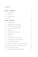
Chapter 1 Introduction 1 1.1 Package Contents 1 1.2 Speciications 2 1.3 Motherboard Layout 7 1.4 I/O Panel 9 Chapter 2 Installation 11 2.1 Installing 26 2.8 Dr. Debug 27 2.9 SLITM and Quad SLITM Operation Guide 29 2.9.1 Installing Two SLITM-Ready Graphics Cards 29 2.9.2 Driver - ASRock Z97 Extreme6/3.1 | User Manual - Page 5
USB 3.1/A+C Installation Guide 39 Chapter 3 Software and Utilities Operation 41 3.1 Installing Drivers 41 3.2 A-Tuning 42 3.3 Intel® Rapid Start Technology 48 3.4 Intel® Smart Connect Technology 53 3.5 ASRock APP Shop 58 3.5.1 UI Overview 58 3.5.2 Apps 59 3.5.3 BIOS & Drivers 62 - ASRock Z97 Extreme6/3.1 | User Manual - Page 6
4.4.5 Intel® Smart Connect Technology 87 4.4.6 Intel® Thunderbolt™ 88 4.4.7 Super IO Coniguration 89 4.4.8 ACPI Coniguration 90 4.4.9 USB Coniguration 92 4.4.10 Trusted Computing 94 4.5 Tools 95 4.6 Hardware Health Event Monitoring Screen 99 4.7 Boot Screen 100 4.8 Security Screen - ASRock Z97 Extreme6/3.1 | User Manual - Page 7
latest VGA cards and CPU support list on ASRock's website as well. ASRock website http://www.asrock.com. 1.1 Package Contents • ASRock Z97 Extreme6/3.1 Motherboard (ATX Form Factor) • ASRock Z97 Extreme6/3.1 Quick Installation Guide • ASRock Z97 Extreme6/3.1 Support CD • 4 x Serial ATA (SATA) Data - ASRock Z97 Extreme6/3.1 | User Manual - Page 8
®/Celeron® Processors (Socket 1150) • Digi Power design • 12 Power Phase design • Supports Intel® Turbo Boost 2.0 Technology • Supports Intel® K-Series unlocked CPUs • Supports ASRock BCLK Full-range Overclocking • Intel® Z97 Memory • Dual Channel DDR3 Memory Technology • 4 x DDR3 DIMM Slots - ASRock Z97 Extreme6/3.1 | User Manual - Page 9
Z97 Extreme6/3.1 Graphics Audio • Intel® HD Graphics Built-in Visuals and the VGA outputs can be supported only with processors which are GPU integrated. • Supports ) • Premium Blu-ray Audio support • Supports Surge Protection (ASRock Full Spike Protection) • Supports Purity Sound™ 2 - Nichicon - ASRock Z97 Extreme6/3.1 | User Manual - Page 10
x DisplayPort 1.2 • 1 x Optical SPDIF Out Port • 1 x eSATA Connector • 2 x USB 3.0 Ports (ASMedia ASM1042AE) (Supports ESD Protection (ASRock Full Spike Protection)) • 4 x USB 3.0 Ports (Intel® Z97) (Supports ESD Protection (ASRock Full Spike Protection)) • 2 x RJ-45 LAN Ports with LED (ACT/LINK LED - ASRock Z97 Extreme6/3.1 | User Manual - Page 11
Z97 Extreme6/3.1 • 4 x SATA3 6.0 Gb/s Connectors by ASMedia ASM1061, support NCQ, AHCI, Hot Plug and ASRock HDD Saver Technology (SATA3_A4 connector is shared with the eSATA port) • 1 x SATA Express Connector (shared with SATA3_4, SATA3_5 and M.2_SSD (NGFF) Socket 3 (M2_2)) * Support to be - ASRock Z97 Extreme6/3.1 | User Manual - Page 12
BIOS with multilingual GUI support (1 x Main BIOS and 1 x Backup BIOS) • Supports Secure Backup UEFI Technology • ACPI 1.1 Compliant wake up events • SMBIOS 2.3.1 Support , please visit our website: http://www.asrock.com Please realize that there is a certain risk involved with overclocking, including - ASRock Z97 Extreme6/3.1 | User Manual - Page 13
Motherboard Layout 1 ATX12V1 CLRC BTN1 Z97 Extreme6/3.1 Z97 SATA3_2_5 SATAE_1 M2_2 NUT4 Super I/O NUT3 NUT5 NUT2 CT1 HD_AUDIO1 1 1 COM1 RoHS PCIE5 PCIE_PWR1 CHA_FAN2 1 T B1 USB3_6_7 1 USB4_5 1 USB2_3 1 BIOS_A_LED BIOS_B_LED CHA_FAN1 Dr. Debug 64Mb BIOS BIOS_A 64Mb BIOS - ASRock Z97 Extreme6/3.1 | User Manual - Page 14
) 15 SATA Express Connector (SATAE_1) 16 Chassis Fan Connector (CHA_FAN1) 17 Chassis Speaker Header (SPEAKER1) 18 Power LED Header (PLED1) 19 BIOS Selection Switch (BIOS_SEL1) 20 Power Switch (PWRBTN1) 21 Reset Switch (RSTBTN1) 22 HDD Saver Connector (SATA_PWR_1) 23 System Panel Header (PANEL1 - ASRock Z97 Extreme6/3.1 | User Manual - Page 15
1.4 I/O Panel 1 2 Z97 Extreme6/3.1 68 3 4 5 79 17 16 15 14 13 12 11 10 No. RJ-45 Port (Intel® I218V)* 13 USB 3.0 Ports (USB3_34) 5 LAN RJ-45 Port (Realtek RTL8111GR)* (Intel® Z97) (USB3 Hub) 6 Central / Bass (Orange) 14 HDMI Port 7 Rear Speaker (Black) 15 eSATA Connector*** 8 - ASRock Z97 Extreme6/3.1 | User Manual - Page 16
use the Rear Speaker, Central/Bass, and Front Speaker, or select "Realtek HDA Audio 2nd output" to use the front panel audio. *** he eSATA connector supports SATA with cables within 1 meters. he SATA3_A4 connector is shared with the eSATA port English 10 - ASRock Z97 Extreme6/3.1 | User Manual - Page 17
Z97 Extreme6/3.1 Chapter 2 Installation his is an ATX form factor motherboard. Before you install the motherboard, study the coniguration of your chassis to ensure that the motherboard its into it. Pre-installation Precautions Take note of the following precautions before you install motherboard - ASRock Z97 Extreme6/3.1 | User Manual - Page 18
2.1 Installing the CPU 1. Before you insert the 1150-Pin CPU into the socket, please check if the PnP cap is on the socket, if the CPU surface is unclean, or if there are any bent pins in the socket. Do not force to insert the CPU into the socket if above situation is found. Otherwise, the CPU will - ASRock Z97 Extreme6/3.1 | User Manual - Page 19
Z97 Extreme6/3.1 3 4 5 13 English - ASRock Z97 Extreme6/3.1 | User Manual - Page 20
Please save and replace the cover if the processor is removed. he cover must be placed if you wish to return the motherboard for ater service. 14 English - ASRock Z97 Extreme6/3.1 | User Manual - Page 21
2.2 Installing the CPU Fan and Heatsink Z97 Extreme6/3.1 1 2 CPU_FAN English 15 - ASRock Z97 Extreme6/3.1 | User Manual - Page 22
2.3 Installing Memory Modules (DIMM) his motherboard provides four 240-pin DDR3 (Double Data Rate 3) DIMM slots, and supports Dual Channel Memory Technology. 1. For dual channel coniguration, you always need to install identical (the same brand, speed, size and chip-type) DDR3 DIMM pairs. 2. - ASRock Z97 Extreme6/3.1 | User Manual - Page 23
Z97 Extreme6/3.1 1 2 3 17 English - ASRock Z97 Extreme6/3.1 | User Manual - Page 24
are 5 PCI Express slots and 1 mini-PCI Express slot on the motherboard. Before installing an expansion card, please make sure that the power supply a better thermal environment, please connect a chassis fan to the motherboard's chassis fan connector (CHA_FAN1, CHA_FAN2 or CHA_FAN3) when using multiple - ASRock Z97 Extreme6/3.1 | User Manual - Page 25
Z97 Extreme6/3.1 2.5 Jumpers Setup he illustration shows how jumpers are setup. When the jumper cap is . However, please do not clear the CMOS right ater you update the BIOS. If you need to clear the CMOS when you just inish updating the BIOS, you must boot up the system irst, and then shut it down - ASRock Z97 Extreme6/3.1 | User Manual - Page 26
place jumper caps over these headers and connectors. Placing jumper caps over the headers and connectors will cause permanent damage to the motherboard. System Panel Header (9-pin PANEL1) (see p.7, No. 23) PLED+ PLEDPWRBTN# GND 1 GND RESET# GND HDLEDHDLED+ Connect the power switch, reset switch - ASRock Z97 Extreme6/3.1 | User Manual - Page 27
SATA3_2_5 SATA3_1_4 SATA3_0_3 SATA3_A1_A2 SATA3_A3_A4 English Z97 Extreme6/3.1 Power LED Header (3-pin PLED1) (see p.7, No. 18) Serial to this header to indicate the system's power status. hese ten SATA3 connectors support SATA data cables for internal storage devices with up to 6.0 Gb/s data - ASRock Z97 Extreme6/3.1 | User Manual - Page 28
No. 26) (USB1) (see p.7, No. 24) USB_PWR PP+ GND DUMMY 1 GND P+ PUSB_PWR here are two headers and one port on this motherboard. Each USB 2.0 header can support two ports. USB 3.0 Headers (19-pin USB3_4_5) (see p.7, No. 8) (19-pin USB3_6_7) (see p.7, No. 27) Vbus IntA_PA_SSRXIntA_PA_SSRX+ GND - ASRock Z97 Extreme6/3.1 | User Manual - Page 29
Z97 Extreme6/3.1 1. High Deinition Audio supports Jack Sensing, but the panel wire on the chassis must support HDA to function correctly. Please follow the instructions in our manual and chassis manual + 12V GN D FAN_SPEED FAN_VOLTAGE GND 4 his motherboard pro- 3 2 vides a 4-Pin CPU fan - ASRock Z97 Extreme6/3.1 | User Manual - Page 30
Header (9-pin COM1) (see p.7, No. 31) 12 24 1 13 8 5 4 1 GND +12V DETECT 1 his motherboard provides a 24-pin ATX power connector. To use a 20-pin ATX power supply, please plug it along Pin 1 and 1 RRI#1 RRTS#1 GND TTXD1 DDCD#1 his COM1 header supports a serial port module. English 24 - ASRock Z97 Extreme6/3.1 | User Manual - Page 31
TPM Header (17-pin TPMS1) (see p.7, No. 33) PCICLK FRAME PCIRST# Z97 Extreme6/3.1 his connector supports Trusted Platform Module (TPM) system, which can securely store keys, digital certiicates, passwords, and data. A TPM system also helps enhance network security, protects digital identities, - ASRock Z97 Extreme6/3.1 | User Manual - Page 32
of your computer and unplug the power supply. BIOS Selection Switch (BIOS_SEL1) (see p.7 No. 19) AB BIOS Selection Switch allows the system to boot from either BIOS A or BIOS B. his motherboard has two BIOS chips, a primary BIOS (BIOS_A) and a backup BIOS (BIOS_ B), which enhances the safety and - ASRock Z97 Extreme6/3.1 | User Manual - Page 33
Z97 Extreme6/3.1 2.8 Dr. Debug Dr. Debug is used to provide code information, which makes troubleshooting even easier. Please see the diagrams below for reading the Dr. Debug codes. Code Description 00 Please check if the CPU is installed correctly and then clear CMOS. 0d Problem related to - ASRock Z97 Extreme6/3.1 | User Manual - Page 34
or try using other memory modules. d6 he VGA could not be recognized. Please clear CMOS and try re-installing the VGA card. If the problem still exists, please try installing the VGA card in other slots or use other VGA cards. d7 he Keyboard and mouse could not be recognized - ASRock Z97 Extreme6/3.1 | User Manual - Page 35
Z97 Extreme6/3.1 2.9 SLITM and Quad SLITM Operation Guide his motherboard supports NVIDIA® SLITM and Quad SLITM (Scalable Link Interface) technology that allows you to install up to two identical PCI Express x16 graphics cards. Currently, NVIDIA® SLITM and Quad SLITM technology supports Windows® 7 / - ASRock Z97 Extreme6/3.1 | User Manual - Page 36
SLI_ Bridge_2S Card to the goldingers on each graphics card. Make sure the ASRock SLI_ Bridge_2S Card is irmly in place. SLI_Bridge_2S Card ASRock SLI_Bridge_2S Card Step 4 Connect a VGA cable or a DVI cable to the monitor connector or the DVI connector of the graphics card that is inserted to - ASRock Z97 Extreme6/3.1 | User Manual - Page 37
Z97 Extreme6/3.1 2.9.2 Driver Installation and Setup Install the graphics card drivers to your system. Ater that, you can enable the Multi-Graphics Processing Unit (GPU) in the - ASRock Z97 Extreme6/3.1 | User Manual - Page 38
Guide his motherboard supports CrossFireXTM, 3-way CrossFireXTM and Quad CrossFireXTM that allows you to install up to three identical PCI Express x16 graphics cards. Currently CrossFireXTM, 3-way CrossFireXTM and Quad CrossFireXTM are supported card manuals for detailed installation guide. 2.10 - ASRock Z97 Extreme6/3.1 | User Manual - Page 39
Z97 Extreme6/3.1 Step 3 Connect a VGA cable or a DVI cable to the monitor connector or the DVI connector of the graphics card that is inserted to PCIE2 slot. 33 English - ASRock Z97 Extreme6/3.1 | User Manual - Page 40
2.10.2 Driver Installation and Setup Step 1 Power on your computer and boot into OS. Step 2 Remove the AMD drivers if you have any VGA drivers installed in your system. he Catalyst Uninstaller is an optional download. We recommend using this utility to uninstall any previously installed Catalyst - ASRock Z97 Extreme6/3.1 | User Manual - Page 41
Z97 Extreme6/3.1 2.11 M.2_SSD (NGFF) Module Installation Guide The M.2, also known as the Next Generation Form Factor (NGFF), is a small size and versatile card edge connector that aims to replace mPCIe and mSATA. The Ultra M.2 Socket (M2_1), supports M.2 PCI Express module up to Gen3 x4 (32 Gb/s). - ASRock Z97 Extreme6/3.1 | User Manual - Page 42
hand. Step 4 Peel of the yellow protective ilm on the nut to be used. Hand tighten the standof into the desired nut location on the motherboard. Step 5 Align and gently insert the M.2 (NGFF) SSD module into the M.2 slot. Please be aware that the M.2 (NGFF) SSD module only its in one orientation - ASRock Z97 Extreme6/3.1 | User Manual - Page 43
Z97 Extreme6/3.1 E D NUT2 NUT1 Step 6 Tighten the screw with a screwdriver to secure the module into place. Please do not overtighten the screw as this might damage the module. M.2_SSD (NGFF) Module Support support list, please visit our website for details: http://www.asrock.com English 37 - ASRock Z97 Extreme6/3.1 | User Manual - Page 44
2.12 HDD Saver Cable Installation Guide The HDD Saver Connector on this motherboard allows you to switch on and off your SATA HDD(s). * he HDD Saver Connector supports up to two SATA HDDs. 2. Connect one end of the SATA data cable to a SATA port on the motherboard. hen connect the other end to your - ASRock Z97 Extreme6/3.1 | User Manual - Page 45
Z97 Extreme6/3.1 2.13 ASRock USB 3.1/A+C Installation Guide Speciications Platform • Size: 3.1-in x 3.2-in, 7.9 cm x 8.1 cm Controller • ASMedia ASM1142 Controller PCIE • PCI Express x4 Connector (x2 lane) • Compliant with PCI Express 1.1, 2.0 and 3.0 speciications • Supports data rates up - ASRock Z97 Extreme6/3.1 | User Manual - Page 46
external USB 3.1 ports which support transfer rates up to 10 Gbps. Follow the simple steps below to install the ASRock USB 3.1/A+C. Step 1 Power x8 or x16 PCI Express slot on your motherboard and remove its slot bracket. *To maximize the performance of ASRock USB 3.1/A+C, it is highly recommended to - ASRock Z97 Extreme6/3.1 | User Manual - Page 47
Z97 Extreme6/3.1 Chapter 3 Software and Utilities Operation 3.1 Installing Drivers he Support CD that comes with the motherboard contains necessary drivers and useful utilities that enhance the motherboard's features. Running The Support CD To begin using the support CD, insert the CD into your CD- - ASRock Z97 Extreme6/3.1 | User Manual - Page 48
3.2.1 Installing A-Tuning When you install the all-in-one driver to your system from ASRock's support CD, A-Tuning will be auto-installed as well. Ater the installation, you will Info, Live Update, Tech Service and Settings. Operation Mode Choose an operation mode for your computer. 42 English - ASRock Z97 Extreme6/3.1 | User Manual - Page 49
Tools Various tools and utilities. Z97 Extreme6/3.1 XFast RAM Boost the system's performance and extend the HDD's computer's boot time. Please note that Ultra Fast mode is only supported by Windows 8.1/8 and the VBIOS must support UEFI GOP if you are using an external graphics card. OMG Schedule - ASRock Z97 Extreme6/3.1 | User Manual - Page 50
speed level when the assigned temperature is met. Dehumidiier Prevent motherboard damages due to dampness. Enable this function and conigure the , current temperature, etc. HDD, SSD and optical disk drives are all supported. he health status block displays Good (in green color), Caution (in yellow - ASRock Z97 Extreme6/3.1 | User Manual - Page 51
OC Tweaker Conigurations for overclocking the system. Z97 Extreme6/3.1 System Info View information about the system. *he System Browser tab may not appear for certain models. 45 English - ASRock Z97 Extreme6/3.1 | User Manual - Page 52
Live Update Check for newer versions of BIOS or drivers. Tech Service Contact Tech Service if you have problems with your computer. Please leave your contact information along with details of the problem. 46 English - ASRock Z97 Extreme6/3.1 | User Manual - Page 53
Z97 Extreme6/3.1 Settings Conigure ASRock A-Tuning. Click to select "Auto run at Windows Startup" if you want A-Tuning to be launched when you start up the Windows operating system. 47 English - ASRock Z97 Extreme6/3.1 | User Manual - Page 54
System Requirements • Conirm whether your motherboard supports this feature. • Operating system: not in AHCI mode, please follow the instructions below. here are certain risks. Please OK. 2. Enter into HKEY_LOCAL_MACHINE\SYSTEM\CurrentControlSet\services\ msahci in Windows Registry Editor. Double - ASRock Z97 Extreme6/3.1 | User Manual - Page 55
Z97 Extreme6/3.1 3. Exit the Registry Editor window and restart the computer. 4. Press F2 to enter BIOS, then go to Advanced ‐> AHCI drivers automatically. 3.3.2 Setup Guide Coniguring Rapid Start Step 1 Run ASRock Rapid Start utility from Start -> All Programs -> ASRock Utility. Step 2 If you - ASRock Z97 Extreme6/3.1 | User Manual - Page 56
Step 3 When prompted to restart ater the setup, click Yes to reboot. English Step 4 Double-click the Intel® Rapid Start Technology Manager icon system tray. in the Windows 50 - ASRock Z97 Extreme6/3.1 | User Manual - Page 57
Z97 Extreme6/3.1 Step 5 Make sure Rapid Start is on. Drag the slider to conigure the time. For example, if the timer value is set to ten minutes, - ASRock Z97 Extreme6/3.1 | User Manual - Page 58
state for a period of time. he power of the computer in Rapid Start mode can be cut of, it will not cause data loss of the programs or iles you were executing before entering sleep state. 4. When you wish to continue to use the computer just hit the power button, the system will rapidly return to - ASRock Z97 Extreme6/3.1 | User Manual - Page 59
Z97 Extreme6 System Requirements • Conirm whether your motherboard supports this feature. • Operating system: not in AHCI mode, please follow the instructions below. here are certain risks. Please 2. Enter into HKEY_LOCAL_MACHINE\SYSTEM\CurrentControlSet\services\ msahci in Windows Registry Editor. - ASRock Z97 Extreme6/3.1 | User Manual - Page 60
3.4.2 Setup Guide Installing ASRock Smart Connect Utility Step 1 Install ASRock Smart Connect Utility, which is located in the folder at the following path of the Support CD: \ ASRock Utility > Smart Connect. Step 2 Once installed, run ASRock Smart Connect from your desktop or go to Windows Start -> - ASRock Z97 Extreme6/3.1 | User Manual - Page 61
Z97 Extreme6/3.1 Step 3 Click the Add button. Take Foxmail as an example, add Foxmail to the Application list. Step 4 Select Foxmail from the Application List, then click - ASRock Z97 Extreme6/3.1 | User Manual - Page 62
Step 6 Double-click the Intel® Smart Connect Technology Manager icon Windows system tray. in the Step 7 Drag the slider to conigure how oten the system will connect to the network to download updates. Shorter durations will provide more frequent updates, but may cause more power consumption. - ASRock Z97 Extreme6/3.1 | User Manual - Page 63
Z97 Extreme6/3.1 4. he system will wake up from sleep state periodically, and then start to update Foxmail. he screen will not display anything so the computer can - ASRock Z97 Extreme6/3.1 | User Manual - Page 64
APP Shop is an online store for purchasing and downloading sotware applications for your ASRock computer. You can install various apps and support utilities quickly and easily, and optimize your system and keep your motherboard up to date simply with a few clicks. Double-click on your desktop to - ASRock Z97 Extreme6/3.1 | User Manual - Page 65
Z97 Extreme6/3.1 3.5.2 Apps When the "Apps" tab is selected, you will see all the available apps on up and down to see more apps listed. You can check the price of the app and whether you have already intalled it or not. - he red icon displays the price or "Free" if the app is free of charge. - he - ASRock Z97 Extreme6/3.1 | User Manual - Page 66
Step 3 If you want to install the app, click on the red icon to start downloading. Step 4 When installation completes, you can ind the green "Installed" icon appears on the upper right corner. English To uninstall it, simply click on the trash can icon . *he trash icon may not appear for certain - ASRock Z97 Extreme6/3.1 | User Manual - Page 67
Z97 Extreme6/3.1 Upgrading an App You can only upgrade the apps you have already installed. When there is an available new version for your app, you will - ASRock Z97 Extreme6/3.1 | User Manual - Page 68
& Drivers" tab is selected, you will see a list of recommended or critical updates for the BIOS or drivers. Please update them all soon. Step 1 Please check the item information before update. Click on Step 2 to see more details. Click to select - ASRock Z97 Extreme6/3.1 | User Manual - Page 69
Z97 Extreme6/3.1 3.5.4 Setting In the "Setting" page, you can change the language, select the server location, and determine if you want to automatically run the ASRock APP Shop on Windows startup. 63 English - ASRock Z97 Extreme6/3.1 | User Manual - Page 70
customizations for greater eiciency. 3.6.1 Installing Start8 Install Start8, which is located in the folder at the following path of the Support CD: \ ASRock Utility > Start8. 3.6.2 Coniguring Start8 Style Select between the Windows 7 style and Windows 8 style Start Menu. hen select the theme of - ASRock Z97 Extreme6/3.1 | User Manual - Page 71
Conigure Z97 Extreme6/3.1 Conigure provides coniguration options, including icon sizes, which shortcuts you want Start Menu to display, quick access to recently used apps, the functionality of the power button, and more. Control 65 English - ASRock Z97 Extreme6/3.1 | User Manual - Page 72
Control lets you conigure what a click on the start button or a press on the Windows key does. Desktop Desktop allows you to disable the hot corners when you are working on the desktop. It also lets you choose whether or not the system boots directly into desktop mode and bypass the Metro user - ASRock Z97 Extreme6/3.1 | User Manual - Page 73
Z97 Extreme6/3.1 Chapter 4 UEFI SETUP UTILITY 4.1 Introduction his section explains how to use the UEFI SETUP UTILITY to conigure your system. You may run the UEFI SETUP UTILITY by pressing or right ater you power on the computer, otherwise, the Power-On-Self-Test (POST) will continue - ASRock Z97 Extreme6/3.1 | User Manual - Page 74
4.1.2 Navigation Keys Use < > key or < > key to choose among the selections on the menu bar, and use < > key or < > key to move the cursor up or down to select items, then press to get into the sub screen. You can also use the mouse to click your required item. Please check the following - ASRock Z97 Extreme6/3.1 | User Manual - Page 75
Z97 Extreme6/3.1 4.2 Main Screen When you enter the UEFI SETUP UTILITY, the Main screen will appear and display the system overview. My Favorite Display your collection of BIOS items. Press F5 to add/remove your favorite items. Active Page on Entry Select the default page when entering the UEFI - ASRock Z97 Extreme6/3.1 | User Manual - Page 76
to increase your system performance. his option appears only when your CPU supports this function. his option appears only when you adopt K-Series CPU. setting. Please note that overclocking may cause damage to your CPU and motherboard. It should be done at your own risk and expense. his option - ASRock Z97 Extreme6/3.1 | User Manual - Page 77
Z97 Extreme6/3.1 Spectrum Enable Spread Spectrum to reduce electromagnetic interference for passing EMI tests. Disable to achieve higher clock speeds when overclocking. CPU OC Fixed note that overclocking may cause damage to your CPU and motherboard. It should be done at your own risk and expense - ASRock Z97 Extreme6/3.1 | User Manual - Page 78
Long Duration Maintained Conigure the period of time until the CPU ratio is lowered when the Long Duration Power Limit is exceeded. Short Duration Power Limit Conigure Package Power Limit 2 in watts. When the limit is exceeded, the CPU ratio will be lowered immediately. A lower limit can protect the - ASRock Z97 Extreme6/3.1 | User Manual - Page 79
Z97 Extreme6/3.1 DRAM Frequency If [Auto] is selected, the motherboard will detect the memory module(s) inserted and assign the appropriate frequency automatically. DRAM Performance Mode Choose high performance mode to increase memory performance. Use default - ASRock Z97 Extreme6/3.1 | User Manual - Page 80
Row Precharge Time (tRP) he number of clock cycles required between the issuing of the precharge command and opening the next row. RAS# Active Time (tRAS) he number of clock cycles required between a bank active command and issuing the precharge command. Command Rate (CR) he delay between when a - ASRock Z97 Extreme6/3.1 | User Manual - Page 81
Z97 Extreme6/3.1 tCKE Conigure the period of time the DDR3 initiates a minimum of one between module write to read delay from diferent ranks. tWRRDDD Use this to change DRAM tRRSR Auto/Manual settings. he default is [Auto]. Conigure between module write to read delay from diferent DIMMs. tWRWR - ASRock Z97 Extreme6/3.1 | User Manual - Page 82
on die termination resistors' WR for channel B. ODT NOM (CHA) Use this to change ODT (CHA) Auto/Manual settings. he default is [Auto]. ODT NOM (CHB) Use this to change ODT (CHB) Auto/Manual settings. he default is [Auto]. Command Tri State Enable for DRAM power saving. MRC Fast Boot Enable Memory - ASRock Z97 Extreme6/3.1 | User Manual - Page 83
Z97 Extreme6/3.1 FIVR Coniguration FIVR Switch Frequency Signature Select whether to boost or lower the FIVR Switch Frequency. FIVR Switch Frequency Ofset Conigure the percentage of frequency - ASRock Z97 Extreme6/3.1 | User Manual - Page 84
Voltage Coniguration Power Saving Mode Enable Power Saving Mode to reduce power consumption. CPU Input Voltage Conigure the voltage for the CPU. CPU Load-Line Calibration CPU Load-Line Calibration helps prevent CPU voltage droop when the system is under heavy load. CPU Input Ofset he ixed external - ASRock Z97 Extreme6/3.1 | User Manual - Page 85
Z97 Extreme6/3.1 4.4 Advanced Screen In this section, you may set the conigurations for the following items: CPU Coniguration, Chipset Coniguration, Storage Coniguration, Intel® Rapid Start Technology, Intel® - ASRock Z97 Extreme6/3.1 | User Manual - Page 86
4.4.1 CPU Coniguration Active Processor Cores Select the number of cores to enable in each processor package. CPU C States Support Enable CPU C States Support for power saving. It is recommended to keep C3, C6 and C7 all enabled for better power saving. Enhanced Halt State (C1E) Enable Enhanced Halt - ASRock Z97 Extreme6/3.1 | User Manual - Page 87
Z97 Extreme6/3.1 CPU Thermal Throttling Enable CPU internal thermal control mechanisms to keep the CPU from overheating. No-Execute Memory Protection Processors with No-Execution Memory Protection - ASRock Z97 Extreme6/3.1 | User Manual - Page 88
4.4.2 Chipset Coniguration Primary Graphics Adapter Select a primary VGA. VT-d Intel® Virtualization Technology for Directed I/O helps your virtual machine monitor better utilize hardware by improving application compatibility and reliability, and providing additional levels of manageability, - ASRock Z97 Extreme6/3.1 | User Manual - Page 89
Z97 Extreme6/3.1 IGPU Multi-Monitor Select disable to disable the integrated graphics when an external graphics card is installed. Select enable to keep the integrated graphics enabled - ASRock Z97 Extreme6/3.1 | User Manual - Page 90
new features that improve performance. RAID: Combine multiple disk drives into a logical unit. AHCI (Advanced Host Controller Interface) supports NCQ and other new features that will improve SATA disk performance but IDE mode does not have these advantages. SATA Aggressive Link Power Management - ASRock Z97 Extreme6/3.1 | User Manual - Page 91
Z97 Extreme6/3.1 Dynamic Storage Accelerator Keep this option enabled for higher HDD and SDD I/O performance, lower latency and increased to SATA3_4, SATA3_5 Force_M2_2: Switch to M2_2 ASMedia SATA3 Mode IDE: For better compatibility. AHCI: Supports new features that improve performance. 85 English - ASRock Z97 Extreme6/3.1 | User Manual - Page 92
4.4.4 Intel® Rapid Start Technology Intel® Rapid Start Technology Intel® Rapid Start Technology is a new zero power hibernation mode which allows users to resume in just 5-6 seconds. 86 English - ASRock Z97 Extreme6/3.1 | User Manual - Page 93
4.4.5 Intel® Smart Connect Technology Z97 Extreme6/3.1 Intel® Smart Connect Technology Intel® Smart Connect Technology automatically updates your email and social networks, such as Twitter, Facebook, etc. while the computer is in sleep mode. English 87 - ASRock Z97 Extreme6/3.1 | User Manual - Page 94
Option Rom Enable to skip hunderbolt™ Option ROM during POST for faster boot speed. TBT Device IO resource Support Enable IO Resource Support if your older hunderbolt devices have trouble working properly. Thunderbolt™ PCIe Cache-line Size Conigure the cache-line size of the hunderbolt PCIe subtree - ASRock Z97 Extreme6/3.1 | User Manual - Page 95
4.4.7 Super IO Coniguration Z97 Extreme6/3.1 PS2 Y-Cable Enable the PS2 Y-Cable or set this option to Auto. Serial Port Enable or disable the Serial port. Serial Port Address Select the address of the Serial port. 89 English - ASRock Z97 Extreme6/3.1 | User Manual - Page 96
is ready, this is recommended for better system stability. ACPI HPET Table Enable the High Precision Event Timer for better performance and to pass WHQL tests. PS/2 Keyboard Power On Allow the system to be waked up by a PS/2 Keyboard. PCIE Devices Power On Allow the system to be waked up - ASRock Z97 Extreme6/3.1 | User Manual - Page 97
Z97 Extreme6/3.1 Ring-In Power On Allow the system to be waked up by onboard COM port modem Ring-In signals. RTC Alarm Power On Allow the - ASRock Z97 Extreme6/3.1 | User Manual - Page 98
entering the OS (USB 3.0 is disabled in BIOS). Set [Enabled] to keep the USB 3.0 driver enabled (Must install driver to use USB devices under Windows® 7). Set [Disabled] to disable the USB 3.0 ports. Legacy USB Support Enable or disable Legacy OS Support for USB 2.0 devices. If you encounter USB - ASRock Z97 Extreme6/3.1 | User Manual - Page 99
Z97 Extreme6/3.1 USB Compatibility Patch If your USB devices (i.e. USB mouse or storage) encounter compatibility problems, please enable this option to ix it. Please note that ater enabling this option, it is normal that the system will postpone booting up ater - ASRock Z97 Extreme6/3.1 | User Manual - Page 100
4.4.10 Trusted Computing Security Device Support Enable or disable BIOS support for security device. 94 English - ASRock Z97 Extreme6/3.1 | User Manual - Page 101
4.5 Tools Z97 Extreme6/3.1 HDD Saver By connecting your HDDs to the onboard SATA power connector with our special designed power cable, you can switch these HDDs on and of when needed. his design allows you to protect your privacy, save more energy, and prolong your HDDs' life spans. English 95 - ASRock Z97 Extreme6/3.1 | User Manual - Page 102
system time are required. UEFI Tech Service Contact ASRock Tech Service if you are having trouble with your PC. Please setup network coniguration before using UEFI Tech Service. Easy RAID Installer Easy RAID Installer helps you to copy the RAID driver from the support CD to your USB storage device - ASRock Z97 Extreme6/3.1 | User Manual - Page 103
Z97 Extreme6/3.1 working ROM image to the secondary lash ROM. Internet Flash ASRock Internet Flash downloads and updates the latest UEFI irmware version from you. Please setup network coniguration before using Internet Flash. *For BIOS backup and recovery purpose, it is recommended to plug in your - ASRock Z97 Extreme6/3.1 | User Manual - Page 104
Dehumidiier Function If Dehumidiier Function is enabled, the computer will power on automatically to dehumidify the system ater entering S4/S5 state. Dehumidiier Period Conigure the period of time until the computer powers on and enables Dehumidiier ater entering S4/S5 state. Dehumidiier Duration - ASRock Z97 Extreme6/3.1 | User Manual - Page 105
Z97 Extreme6/3.1 4.6 Hardware Health Event Monitoring Screen his section allows you to monitor the status of the hardware on your system, including the parameters of the CPU temperature, motherboard temperature, fan speed and voltage. CPU Fan 1 & 2 Setting Select a fan mode for CPU Fans 1&2, or - ASRock Z97 Extreme6/3.1 | User Manual - Page 106
minimizes your computer's boot time. In fast mode you may not boot from an USB storage device. Ultra Fast mode is only supported by Windows 8.1/8 and the VBIOS must support UEFI GOP if you are using an external graphics card. Please notice that Ultra Fast mode will boot so fast that the - ASRock Z97 Extreme6/3.1 | User Manual - Page 107
Z97 Extreme6/3.1 Full Screen Logo Enable to display the boot logo or disable restores the default settings. CSM (Compatibility Support Module) CSM Enable to launch the Compatibility Support Module. Please do not disable unless you're running a WHCK test. If you are using Windows 8.1/8 64 - ASRock Z97 Extreme6/3.1 | User Manual - Page 108
Launch Storage OpROM Policy Select UEFI only to run those that support UEFI option ROM only. Select Legacy only to run those that support legacy option ROM only. Do not launch? Launch Video OpROM Policy Select UEFI only to run those that support UEFI option ROM only. Select Legacy only to run those - ASRock Z97 Extreme6/3.1 | User Manual - Page 109
Z97 Extreme6/3.1 4.8 Security Screen In this section you may set or change the supervisor/user password for the system. You may also clear settings in the UEFI Setup Utility. Leave it blank and press enter to remove the password. Secure Boot Enable to support Windows 8.1 / 8 Secure Boot. 103 English - ASRock Z97 Extreme6/3.1 | User Manual - Page 110
4.9 Exit Screen Save Changes and Exit When you select this option the following message, "Save coniguration changes and exit setup?" will pop out. Select [OK] to save changes and exit the UEFI SETUP UTILITY. Discard Changes and Exit When you select this option the following message, "Discard changes - ASRock Z97 Extreme6/3.1 | User Manual - Page 111
Z97 Extreme6/3.1 Contact Information If you need to contact ASRock or want to know more about ASRock, you're welcome to visit ASRock's website at http://www.asrock.com; or you may contact your dealer for further information. For technical questions, please submit a support request form at http://www
-
 1
1 -
 2
2 -
 3
3 -
 4
4 -
 5
5 -
 6
6 -
 7
7 -
8
-
9
-
10
-
11
-
12
-
13
-
14
-
15
-
16
-
17
-
18
-
19
-
20
-
21
-
22
-
23
-
24
-
25
-
26
-
27
-
28
-
29
-
30
-
31
-
32
-
33
-
34
-
35
-
36
-
37
-
38
-
39
-
40
-
41
-
42
-
43
-
44
-
45
-
46
-
47
-
48
-
49
-
50
-
51
-
52
-
53
-
54
-
55
-
56
-
57
-
58
-
59
-
60
-
61
-
62
-
63
-
64
-
65
-
66
-
67
-
68
-
69
-
70
-
71
-
72
-
73
-
74
-
75
-
76
-
77
-
78
-
79
-
80
-
81
-
82
-
83
-
84
-
85
-
86
-
87
-
88
-
89
-
90
-
91
-
92
-
93
-
94
-
95
-
96
-
97
-
98
-
99
-
100
-
101
-
102
-
103
-
104
-
105
-
106
-
107
-
108
-
109
-
110
-
111
 |
 |

Z97 Extreme6
/
3.1
Z97 Extreme6
/
3.1
User Manual