Acer AW2000h-AW175h F1 Acer AW2000h-AW17xhx Service Guide
Acer AW2000h-AW175h F1 Manual
 |
View all Acer AW2000h-AW175h F1 manuals
Add to My Manuals
Save this manual to your list of manuals |
Acer AW2000h-AW175h F1 manual content summary:
- Acer AW2000h-AW175h F1 | Acer AW2000h-AW17xhx Service Guide - Page 1
Acer AW2000h Service Guide PART NO.: PRINTED IN TAIWAN - Acer AW2000h-AW175h F1 | Acer AW2000h-AW17xhx Service Guide - Page 2
customer machines. Revision History Please refer to the table below for the updates made on Acer AW2000h service guide. Date Chapter Updates Copyright Copyright © 2010 by Acer Inc. All rights reserved. No part of this publication may be reproduced, transmitted, transcribed, stored in a retrieval - Acer AW2000h-AW175h F1 | Acer AW2000h-AW17xhx Service Guide - Page 3
information related to the current topic. Alerts you to any damage that might result from doing or not doing specific actions. Gives precautionary measures to avoid possible hardware or software problems. Reminds you to do specific actions relevant to the accomplishment of procedures. Chapter - Acer AW2000h-AW175h F1 | Acer AW2000h-AW17xhx Service Guide - Page 4
them. CAUTION: Do not operate the server for long periods with the access panel open or removed. Operating the server in this manner results in improper airflow and improper cooling that can lead to thermal damage. Preventing electrostatic discharge To prevent damaging the system, be aware of the - Acer AW2000h-AW175h F1 | Acer AW2000h-AW17xhx Service Guide - Page 5
Table of Contents Preface ii Safety, Care and Regulatory Information iv System components 1 System parts list 2 Removal and replacement procedures 3 Extend the server from the rack 4 Power down the server 6 Remove the server from the rack 7 System specifications 9 Hardware - Acer AW2000h-AW175h F1 | Acer AW2000h-AW17xhx Service Guide - Page 6
Control 67 Security Settings 72 System Management Settings 73 Boot 75 Exit Options 76 BIOS Beep Codes 77 BIOS POST Error Messages List 81 Using Acer Smart Console 83 Accessing Acer Smart Console 84 Acer Smart Console user interface 85 vi - Acer AW2000h-AW175h F1 | Acer AW2000h-AW17xhx Service Guide - Page 7
System components Chapter 1 Item 1 2 3 4 5 6 7 8 9 10 11 12 13 14 15 16 Description Mainboard Memory CPU Heatsink Air shroud Power supply Riser card bracket Riser card Rack rails Mainboard tray Top cover Chassis Backplane Hard disk drive Fans Mainboard to backplane board Chapter 1 1 - Acer AW2000h-AW175h F1 | Acer AW2000h-AW17xhx Service Guide - Page 8
System parts list Currently unavailable. 2 Chapter 1 - Acer AW2000h-AW175h F1 | Acer AW2000h-AW17xhx Service Guide - Page 9
following procedures: • Extend the server from the rack If you are performing service procedures in an Acer branded, telco, or third-party rack cabinet, you can use the locking feature of the rack rails to support the server and gain access to internal components. For more information about telco - Acer AW2000h-AW175h F1 | Acer AW2000h-AW17xhx Service Guide - Page 10
Extend the server from the rack 1. If the server is screwed into the rack, remove the screws and set them aside. 4 Chapter 2 - Acer AW2000h-AW175h F1 | Acer AW2000h-AW17xhx Service Guide - Page 11
2. Grasp the handles and extend the server from the rack. WARNING:To reduce the risk of personal injury or equipment damage, be sure that the rack is adequately stabilized before extending a component from the rack. 3. After performing the installation or maintenance procedure, slide the server - Acer AW2000h-AW175h F1 | Acer AW2000h-AW17xhx Service Guide - Page 12
Power down the server WARNING: To reduce the risk of personal injury, electric shock, or damage to the equipment, remove the power cord to remove power from the server. The front panel Power On/Standby button does not completely shut off system power. Portions of the power supply and some internal - Acer AW2000h-AW175h F1 | Acer AW2000h-AW17xhx Service Guide - Page 13
Remove the server from the rack To remove the server from an HP, Compaq branded, telco, or third-party rack: 1. Power down the server. 2. Extend the server from the rack 3. Disconnect the cabling and remove the server from the rack. For more information, refer to the documentation that ships with - Acer AW2000h-AW175h F1 | Acer AW2000h-AW17xhx Service Guide - Page 14
8 Chapter 2 - Acer AW2000h-AW175h F1 | Acer AW2000h-AW17xhx Service Guide - Page 15
System specifications Hardware specifications System unit Specifications Processor socket Processor support Core logic chipsets LAN controller Memory controller Storage controller VGA controller I/O subsystem Memory Media storage I/O ports Status LED indicators Thermal solution Value Two Intel - Acer AW2000h-AW175h F1 | Acer AW2000h-AW17xhx Service Guide - Page 16
Environmental specifications Specifications Temperature range Operating Non-operating Humidity (non-condensing) Operating Non-operating Altitude Operating Non-operating Acoustic noise Idle, minimum (fixed disk drives spinning) Operating, minimum (random seeks to fixed disk drives) Value 10°C to 35 - Acer AW2000h-AW175h F1 | Acer AW2000h-AW17xhx Service Guide - Page 17
Mechanical specifications Specifications System board platform System board dimensions Length Width Server dimensions Height Width Depth Server weight Barebone Basic configuration (excluding keyboard and mouse) Fully loaded configuration (including keyboard, mouse and kits) Proprietary Value 417 - Acer AW2000h-AW175h F1 | Acer AW2000h-AW17xhx Service Guide - Page 18
Power supply specifications Specifications Model Type Dimensions Height Depth Width Weight (approximate) Input requirements Rated input voltage Normal line voltage Line frequency Rated input current Inrush current Power supply output power Rated steady state power Maximum peak power Operating - Acer AW2000h-AW175h F1 | Acer AW2000h-AW17xhx Service Guide - Page 19
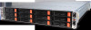
System appearance Front view Chapter 4 No. 1 2 3 4 5 6 7 8 9 10 11 12 13 14 15 Icon Component Power button/indicator LAN activity indicator Status/fault indicator System ID button/indicator Three 3.5-inch hot-plug drive bays (A0 to A2) for node A Three 3.5-inch hot-plug drive bays (B0 to B2) for - Acer AW2000h-AW175h F1 | Acer AW2000h-AW17xhx Service Guide - Page 20
RJ-45) (10/100 Mbps) PCI expansion slot Server node B Server node A System ID switch InfiniBand port QSFP connector (only available for GW170hd F1 and GW170hq F1) Monitor port Serial port (COM 1) Gigabit LAN ports (10/100/1000 Mbps) USB 2.0 ports Power socket Server node C Server node D 14 Chapter - Acer AW2000h-AW175h F1 | Acer AW2000h-AW17xhx Service Guide - Page 21
Internal components No. 1 2 3 4 5 6 7 Component Hard disk drives System fan modules Memory module (DIMM) sockets Air duct PCI riser board bracket assembly Mainboard Power supply module Chapter 4 15 - Acer AW2000h-AW175h F1 | Acer AW2000h-AW17xhx Service Guide - Page 22
on the : • Front panel • Hot-plug HDD carrier • Rear panel • LAN port Knowing what each LED indicator signifies can aid in problem diagnosis and troubleshooting. Front panel LED indicators LED indicator Power indicator LED color Green Green Status/fault indicator LAN activity indicator System ID - Acer AW2000h-AW175h F1 | Acer AW2000h-AW17xhx Service Guide - Page 23
Hard disk drive sequence and LED indicators The hard drive sequence is as follows: Node B control panel Node D control panel Node A control panel Drive bays for node A Drive bays for node B Node C control panel Drive bays for node C Drive bays for node D Bay no. Node A HDD A0 to A2 Node B - Acer AW2000h-AW175h F1 | Acer AW2000h-AW17xhx Service Guide - Page 24
LAN Port LED indicators LED indicator RJ45 LED (Left) RJ45 LED (Right) LED color N/A Green Amber Yellow Yellow LED state Off On On On Blinking Status No connection or 10 Mbps 100 Mbps 1000 Mbps Active connection Transmit/Receive activity 18 Chapter 4 - Acer AW2000h-AW175h F1 | Acer AW2000h-AW17xhx Service Guide - Page 25
System block diagram #1 #1 #1 #2 #2 #2 A B C A B PROCESSOR#0 C QPI PROCESSOR#1 #2 #2 #2 D D E E F F #1 #1 #1 DDR3 DIMM DDR3 DIMM DDR3 DIMM DDR3 DIMM RJ-45 QSFP MT25408 Connect-X IB PCI-E Gen2/DDR or QDR (For 36D Only) IOH 5520/5500 36-D/24-D Intel 82574 Intel 82574 RJ-45 PCI-E - Acer AW2000h-AW175h F1 | Acer AW2000h-AW17xhx Service Guide - Page 26
20 Chapter 4 - Acer AW2000h-AW175h F1 | Acer AW2000h-AW17xhx Service Guide - Page 27
power button on its own control panel. An additional power supply module may be added to provide redundant power. Both the GW170hd F1 and GW170hq F1 models include an InfiniBand port at DDR (dual data rate) and QDR (quad data rate) speeds, respectively. InfiniBand is a scalable serial communications - Acer AW2000h-AW175h F1 | Acer AW2000h-AW17xhx Service Guide - Page 28
LAN 10 JPL1/JPL2 Description Unit identifier switch Alarm reset header InfiniBand connector QSFP connector (only available for GW170hd F1 and GW170hq F1). Video port Internal speaker/buzzer header COM1 serial port Gigabit Ethernet (RJ45) ports Universal Serial Bus (USB) ports 0/1, 2/3 Dedicated - Acer AW2000h-AW175h F1 | Acer AW2000h-AW17xhx Service Guide - Page 29
No. 11 12 13 14 15 16 17 18 19 Connector JPG1 IPMB JBAT1 P2 DIMM1B, P2 DIMM1A, P2 DIMM2B, P2 DIMM2A, P2 DIMM3B, P2 DIMM3A, FAN 1 CPU1 P1 DIMM1B, P1 DIMM1A, P1 DIMM2B, P1 DIMM2A, P1 DIMM3B, P1 DIMM3A, JWR JF2 20 CPU2 21 Slot 1 22 JNMI1 23 JWD1 Description VGA Enable/Disable IPMB header (for - Acer AW2000h-AW175h F1 | Acer AW2000h-AW17xhx Service Guide - Page 30
Mainboard jumpers No. 1 2 3 4 Jumper JWD1 JBT1 JPG1 JPL1/ JPL2 Description Default Setting Enable/Disable/Reset Pins 1-2 (Reset) Watch Dog Clear CMOS Instead of pins, this jumper consists of contact pads to prevent accidental clearing of the CMOS contents. To clear CMOS, disconnect the power - Acer AW2000h-AW175h F1 | Acer AW2000h-AW17xhx Service Guide - Page 31
LE1 Description System ID LED indicator (rear) InfiniBand link LED indicator (only available for GW170hd F1 and GW170hq F1) InfiniBand activity LED indicator (only available for GW170hd F1 and GW170hq F1) BMC Heartbeat LED Indicator HDD/SATA LED Indicator Onboard standby PWR warning LED Indicator - Acer AW2000h-AW175h F1 | Acer AW2000h-AW17xhx Service Guide - Page 32
26 Chapter 5 - Acer AW2000h-AW175h F1 | Acer AW2000h-AW17xhx Service Guide - Page 33
step-by-step procedures on how to disassemble the server SATA backplane board for maintenance and troubleshooting. To disassemble the server, please pay attention to each section's instruction and tools needed. NOTE: The screws for the different components vary in size. During the disassembly - Acer AW2000h-AW175h F1 | Acer AW2000h-AW17xhx Service Guide - Page 34
SATA ports The backplane is designed with four separate sectors which support from one to four mainboards independently of each other. The table below will help you determine the SATA port to mainboard configuration that is appropriate - Acer AW2000h-AW175h F1 | Acer AW2000h-AW17xhx Service Guide - Page 35
Backplane connectors Front view No. 1 2 3 4 5 6 7 8 9 10 11 12 13 14 Connector JP57 JP56 JF4 JP55 JP54 JPW3 JF2 JF1 JPW2 J5 JPI2C1 JPW1 JF3 J6 Description Function Chassis fan 4 connector Chassis fan 3 connector Supply power to the chassis cooling fans. MB-D hot plug connector Connect the - Acer AW2000h-AW175h F1 | Acer AW2000h-AW17xhx Service Guide - Page 36
Rear view No. 1 2 3 4 5 6 7 8 9 10 11 12 Connector J1 J2 J3 J4 J9 J11 J13 J15 J17 J18 J19 J20 Description SATA #A0 SATA #A1 SATA #A2 SATA #B0 SATA #B1 SATA #B2 SATA #C0 SATA #C1 SATA #C2 SATA #D0 SATA #D1 SATA #D2 Function SATA HDD A0 SATA HDD A1 SATA HDD A2 SATA HDD B0 SATA HDD B1 SATA HDD B2 - Acer AW2000h-AW175h F1 | Acer AW2000h-AW17xhx Service Guide - Page 37
Backplane jumpers No. Jumper 1 JP30 2 JP18 3 JP69 4 J21 5 JP36 6 JP35 Description Setting Backplane overheat settings Open: 45 deg C 1-2: 50 deg C 2-3: 55 deg C Buzzer reset Open: Disabled 1-2: Enabled 2-3: Test setting FW upgrade connector Any power button LED testing Open: - Acer AW2000h-AW175h F1 | Acer AW2000h-AW17xhx Service Guide - Page 38
Backplane LED indicators Front view No. 1 2 LED D11 D1 Rear view ON Blinking State Specification Indicates an overheat condition Indicates backplane activity No. 1 2 3 4 5 6 7 8 9 10 11 12 Connector SATA #A2 SATA #A1 SATA #A0 SATA #B2 SATA #B1 SATA #B0 SATA #C2 SATA #C1 SATA #C0 SATA #D2 - Acer AW2000h-AW175h F1 | Acer AW2000h-AW17xhx Service Guide - Page 39
chapter contains step-by-step procedures on how to disassemble the server system for maintenance and troubleshooting. To disassemble the server, please pay attention to each section's instruction and tools needed. NOTE: The screws for the different components vary in size. During the disassembly - Acer AW2000h-AW175h F1 | Acer AW2000h-AW17xhx Service Guide - Page 40
Hard disk drive removal and installation The system has four drive bays. Follow these steps: 1. Remove the hard disk drive carrier. a. Unlock the HDD carrier latch b. Slide the HDD carrier latch to trelease the lever. c. Pull the lever and slide the carrier from the chassis. 2. Replace the hard - Acer AW2000h-AW175h F1 | Acer AW2000h-AW17xhx Service Guide - Page 41
c. Lock the HDD carrier. Hardware removal and installation 35 - Acer AW2000h-AW175h F1 | Acer AW2000h-AW17xhx Service Guide - Page 42
Power supply removal and installation The system uses a single 1200W/1400W power supply module which operates at 100 to 140/180 to 240V. You can install a second power module for hot-plug and redundancy. Follow these steps: 1. Power down the server and unplug the power cord. 2. Remove the power - Acer AW2000h-AW175h F1 | Acer AW2000h-AW17xhx Service Guide - Page 43
Replacing a server node If you need to replace a server node module, follow these steps: 1. Turn off the power to the node module. 2. Press the tabs (1) on both sides and use the handles (2) to pull out and remove the node module. 3. Insert a new node module into the vacated server node bay. - Acer AW2000h-AW175h F1 | Acer AW2000h-AW17xhx Service Guide - Page 44
PCI Express card removal and installation Your server has two preinstalled riser cards designed specifically for use in the 1U rackmount chassis. These riser cards allow two low-profile PCI Express x16 cards to fit inside the chassis. Installing a PCI Express card 1. Remove the server node. See - Acer AW2000h-AW175h F1 | Acer AW2000h-AW17xhx Service Guide - Page 45
Replacing the riser card Follow these steps: 1. Remove any installed PCI Express card. See "PCI Express card removal and installation" on page 38. 2. Remove the screw securing the PCI Express card bracket (1); then pull up the bracket and the riser card. 3. To remove the riser card from the bracket, - Acer AW2000h-AW175h F1 | Acer AW2000h-AW17xhx Service Guide - Page 46
Top cover removal and installation Follow these steps: 1. Remove the two screws securing the top cover to the chassis. 2. Lift the cover off the chassis. 3. Put the top cover aside for reinstallation later. To install the top cover: 1. Align the top cover tabs with the slots on the chassis. 2. Close - Acer AW2000h-AW175h F1 | Acer AW2000h-AW17xhx Service Guide - Page 47
Air duct removal and installation CAUTION: Always operate your server with the air duct installed to ensure reliable and continued operation. Follow these steps: 1. Open the top cover. See "PCI Express card removal and installation" on page 38. 2. Lift up the air duct. To install the air duct, place - Acer AW2000h-AW175h F1 | Acer AW2000h-AW17xhx Service Guide - Page 48
Fan removal and installation The system has a total of four high-performance fans to provide the cooling for the system. Follow these steps: 1. With the server powered on, open the top cover. See "PCI Express card removal and installation" on page 38. 2. Determine which of the fans has failed. 3. - Acer AW2000h-AW175h F1 | Acer AW2000h-AW17xhx Service Guide - Page 49
Heatsink removal and installation Follow these steps: 1. Power down the server and unplug the power cord. 2. Open the top cover. See "PCI Express card removal and installation" on page 38. 3. Using a screwdriver, loosen the heatsink screws from the mainboard. 4. Lift the heat sink away from the - Acer AW2000h-AW175h F1 | Acer AW2000h-AW17xhx Service Guide - Page 50
5. Screw in two diagonal screws (i.e. the #1 and the #2 screws) until just snug. Do not fully tighten the screws or you may damage the CPU.) 6. Add the two remaining screws then finish the installation by fully tightening all four screws. 44 Chapter 7 - Acer AW2000h-AW175h F1 | Acer AW2000h-AW17xhx Service Guide - Page 51
CPU removal and installation The mainboard has two LGA 1366 processor sockets supporting dual-core or quad-core Intel Xeon processors. You have the option to upgrade the default processor or install a second one for a dual-processor configuration. - Acer AW2000h-AW175h F1 | Acer AW2000h-AW17xhx Service Guide - Page 52
a. Hold the processor by its edges. Make sure the alignment tabs on the socket fit the two notch located on the edge of the processor. The pins are keyed in such a way that you cannot install the processor in the wrong orientation without bending the pins. b. Insert the new processor in the socket. - Acer AW2000h-AW175h F1 | Acer AW2000h-AW17xhx Service Guide - Page 53
3A in blue) and B (PxDIMM1B, 2B, 3B in black). So, the system has a total of twelve memory slots. The memory slots support DDR3-1333 registered/unbuffered ECC memory modules. The folllowing illustration shows the processor 1 memory slots (1) and processor 2 memory slots (2). Independent mode • For - Acer AW2000h-AW175h F1 | Acer AW2000h-AW17xhx Service Guide - Page 54
NA NA X X NA NA X X X X NA NA X X X X NA NA Notes: 1. Place DIMMs in "X" location. 2. DIMM population must correspond to the above tables. 3. DIMM modules support 1 GB, 2 GB, 4 GB and 8 GB DIMMS. 4. The size of each DIMM must be the same across the configuration. 5. Do not mix UDIMMs with - Acer AW2000h-AW175h F1 | Acer AW2000h-AW17xhx Service Guide - Page 55
, 4 GB and 8 GB DIMMS. 4. The size of each DIMM must be the same across the configuration. 5. Do not mix UDIMMs with RDIMMs. Sparing mode (only supported on Intel Xeon Processor 5600 Series CPUs) • In this mode, if the system detects degrading memory and did not crash, the data in the failed - Acer AW2000h-AW175h F1 | Acer AW2000h-AW17xhx Service Guide - Page 56
but the convention is usually like this: Density Rank Bit organization Speed Item Description Density 1GB, 2GB,4GB,8GB. Intel Xeon Processor 5500 Series CPU supports DIMM organized by 1Gb or 2Gb DRAM chips. Rank 1R = Single Rank 2R = Dual Rank 4R = Quad Rank Note: If quad rank DIMM is used - Acer AW2000h-AW175h F1 | Acer AW2000h-AW17xhx Service Guide - Page 57
b. Push the DIMM to the socket until the retaining clips snap inward. NOTE: The DIMM slot is slotted to ensure proper installation. If you insert a DIMM but it does not fit easily into the socket, you may have inserted it incorrectly. Reverse the orientation of the DIMM and insert it again. 6. - Acer AW2000h-AW175h F1 | Acer AW2000h-AW17xhx Service Guide - Page 58
Battery removal and installation Follow these steps: 1. Power down the server and unplug the power cord. 2. Open the top cover. See "PCI Express card removal and installation" on page 38. 3. Remove the air duct. See "Air duct removal and installation" on page 41. 4. Locate the coin battery. 5. - Acer AW2000h-AW175h F1 | Acer AW2000h-AW17xhx Service Guide - Page 59
Optional parts installation and removal The server supports the following optional parts: • External USB optical drive External USB optical drive Connect an external USB optical drive to an available USB port: Hardware removal and installation 53 - Acer AW2000h-AW175h F1 | Acer AW2000h-AW17xhx Service Guide - Page 60
Mainboard removal and installation To remove the mainboard, follow these steps: 1. Power down the server node module. See "Switch and LED indicators" on page 16. 2. Press the tabs (1) on both sides and use the handles (2) to pull out and remove the node module. 3. Remove the air duct. 4. Remove any - Acer AW2000h-AW175h F1 | Acer AW2000h-AW17xhx Service Guide - Page 61
9. Remove eight screws that secure the mainboard to the mainboard tray. Then remove two screws that secure the mainboard-to-backplane board to the mainboard tray. 10. Pull out the mainboard from the mainboard tray. Hardware removal and installation 55 - Acer AW2000h-AW175h F1 | Acer AW2000h-AW17xhx Service Guide - Page 62
11. Disconnect the mainboard-to-backplane board from the mainboard. To install a mainboard, reverse the steps above. 56 Chapter 7 - Acer AW2000h-AW175h F1 | Acer AW2000h-AW17xhx Service Guide - Page 63
Rackmount installation procedure CAUTION: To minimize the chances of injuries, make sure that two or more people help in installing the server. Follow these steps to install the system into a four-post rack: 1. Confirm that the left and right inner rails have been correctly identified. 2. Remove the - Acer AW2000h-AW175h F1 | Acer AW2000h-AW17xhx Service Guide - Page 64
of two holes with closer spacing to the center of the next pair is equivalent to 1U. NOTE: The unit of measurement used in this guide is "U" (1U = 1.75 inches or 44.45 mm). The total sum of the heights of all components in the rack measured in "U" cannot exceed the - Acer AW2000h-AW175h F1 | Acer AW2000h-AW17xhx Service Guide - Page 65
6. Pull out the server mounting rails from the left and right mounting rails. CAUTION: To avoid personal injury, care should be taken when pressing the inner rail release latches and sliding the component into the rack. 7. Install the server into the rack. a. Insert the inner rails into the server - Acer AW2000h-AW175h F1 | Acer AW2000h-AW17xhx Service Guide - Page 66
b. Press the release latch (2) and continue to push the server (3) into the rack until you hear a click sound 8. For security purposes, tighten the right and left thumbscrews on the front panel to secure the server to the front of the rack as illustrated below. 60 Chapter 7 - Acer AW2000h-AW175h F1 | Acer AW2000h-AW17xhx Service Guide - Page 67
contact that could short out power. 4. If the problem is not evident, continue with System Internal Inspection. System surface. 6. Remove the system cover. For instructions on removing system cover, refer to disassembling all components are Acer-qualified and supported. 10. Replace the system cover. - Acer AW2000h-AW175h F1 | Acer AW2000h-AW17xhx Service Guide - Page 68
the recovery image and starts the BIOS recovery flash operation. When the flash operation completes, the system will reboot automatically. The system will show the result of the recovery process once it completes. 62 Chapter 8 - Acer AW2000h-AW175h F1 | Acer AW2000h-AW17xhx Service Guide - Page 69
. Each main BIOS menu option is described in this manual. The Main BIOS setup menu screen has two main NOTE: The BIOS has default text messages built in. Acer retains the option to include, omit or change any of the setup navigation process. These keys include , , , and arrow - Acer AW2000h-AW175h F1 | Acer AW2000h-AW17xhx Service Guide - Page 70
Main setup When you first enter the BIOS setup utility, you will enter the main setup screen. You can always return to the main setup screen by selecting the main tab on the top of the screen. The main BIOS setup screen is shown below. System Overview System Time/System Date Use this option to - Acer AW2000h-AW175h F1 | Acer AW2000h-AW17xhx Service Guide - Page 71
Power-on state for Numlock key. Wait For 'F1' If Error: Forces the system to wait until the key is pressed if an error occurs. supported by the processor and/or operating system. Hardware Prefetcher: If set to Enabled, the hardware prefetcher will prefetch streams of data and instructions - Acer AW2000h-AW175h F1 | Acer AW2000h-AW17xhx Service Guide - Page 72
during an attack. IMPORTANT:The following feature is only available if supported by the processor and/or operating system. Simultaneous Multi-Threading: Set to Enabled to use simultaneous multi-threading technology, which will result in increased CPU performance. Intel EIST Technology: EIST (Enhanced - Acer AW2000h-AW175h F1 | Acer AW2000h-AW17xhx Service Guide - Page 73
Advanced Chipset Control The items included in the Advanced Settings submenu are listed below: CPU Bridge configuration QPI Links Speed: This feature selects QPI data transfer speed. IMPORTANT:The following feature is only available when QPI Links Speed is set to Full Speed. QPI Frequency: This - Acer AW2000h-AW175h F1 | Acer AW2000h-AW17xhx Service Guide - Page 74
the coalesce feature. Please refer to your add-on card user guide for the desired setting. South Bridge configuration This feature allows you to not, contact your manufacturer or install an ATA/133 IDE controller card that supports 48-bit LBA mode. • Block (Multi-Sector Transfer) - Block Mode - Acer AW2000h-AW175h F1 | Acer AW2000h-AW17xhx Service Guide - Page 75
Description Automatically detect the PIO mode. Use this value if the IDE disk drive support cannot be determined. Use PIO mode 0. It has a data transfer rate of not required for system boot if your system has an oerating system that supports Plug & Play.) Select No to allow the BIOS to configure all - Acer AW2000h-AW175h F1 | Acer AW2000h-AW17xhx Service Guide - Page 76
CPU can now send information to the motherboard what its Temperature Tolerance is, and not the other way around. This results in better CPU thermal management. Acer has leveraged this feature by assigning a temperature status to certain thermal conditions in the processor (Low, Medium and High - Acer AW2000h-AW175h F1 | Acer AW2000h-AW17xhx Service Guide - Page 77
, chassis ventilation and room temperature to correct any problems. NOTE: The system may shut down if it website for further explanation: http://www.acpi.info/. ACPI APIC Support: Select Enabled to include the ACPI APIC Table Pointer in the , such as an x86 RDTSC Instruction embedded in the CPU. The - Acer AW2000h-AW175h F1 | Acer AW2000h-AW17xhx Service Guide - Page 78
Security Settings The BIOS provides a Supervisor and a User password. If you use both passwords, the Supervisor password must be set first. Supervisor Password: This item indicates if a supervisor password has been entered for the system. Clear means such a password has not been used and Set means a - Acer AW2000h-AW175h F1 | Acer AW2000h-AW17xhx Service Guide - Page 79
on a table containing MAC Address/IP Address pairs that are manually entered (such as by a network administrator). Only clients with 60). Remote Access Configuration Remote Access: This allows you to enable Remote Access support. If Remote Access is set to Enabled, the following items will be - Acer AW2000h-AW175h F1 | Acer AW2000h-AW17xhx Service Guide - Page 80
: Select Enabled to enable VT-UTF8 Combination Key support for ANSI/ VT100 terminals. Sredir Memory Display Delay: Defines the length of time in seconds to display memory information. Event Log Configuration View Event Log: - Acer AW2000h-AW175h F1 | Acer AW2000h-AW17xhx Service Guide - Page 81
Boot This submenu allows you to configure boot settings for the system. Boot Device Priority This feature allows you to specify the sequence of priority for the Boot Device. • 1st Boot Device • 2nd Boot Device • 3rd Boot Device Hard Disk Drives This feature allows you to specify the boot sequence - Acer AW2000h-AW175h F1 | Acer AW2000h-AW17xhx Service Guide - Page 82
Exit Options Select the Exit tab from the BIOS Setup Utility screen to enter the Exit BIOS Setup screen. Save Changes and Exit: When you have completed the system configuration changes, select this option to leave the BIOS Setup Utility and reboot the computer, so the new system configuration - Acer AW2000h-AW175h F1 | Acer AW2000h-AW17xhx Service Guide - Page 83
Chapter 10 BIOS Beep Codes During POST (Power-On Self-Test) routines, which are performed each time the system is powered on, errors may occur. Non-fatal errors are those, which, in most cases, allow the system to continue the boot-up process. The error messages normally appear on the screen. Fatal - Acer AW2000h-AW175h F1 | Acer AW2000h-AW17xhx Service Guide - Page 84
Troubleshooting POST BIOS beep codes Number of Beeps 1, 3 6, 7 8 Description Reseat the memory, or replace with known good modules. Fatal error indicating a serious problem expansion cards are absent, consult your system manufacturer's technical support. • If beep codes are not generated when all - Acer AW2000h-AW175h F1 | Acer AW2000h-AW17xhx Service Guide - Page 85
Chapter 10 79 - Acer AW2000h-AW175h F1 | Acer AW2000h-AW17xhx Service Guide - Page 86
80 Chapter 10 - Acer AW2000h-AW175h F1 | Acer AW2000h-AW17xhx Service Guide - Page 87
BIOS POST Error Messages List Information unavailable. Chapter 11 Chapter 11 81 - Acer AW2000h-AW175h F1 | Acer AW2000h-AW17xhx Service Guide - Page 88
82 Chapter 11 - Acer AW2000h-AW175h F1 | Acer AW2000h-AW17xhx Service Guide - Page 89
role-based management. User accounts are separated into three levels: No access, operator and administrator. Acer Smart Console also provides RADIUS and LDAP Client Support. Software requirements Supported environments: Microsoft Windows Vista, XP, Windows 2000, 2003 and Server 2008. JAVA: Version - Acer AW2000h-AW175h F1 | Acer AW2000h-AW17xhx Service Guide - Page 90
to enter a username and password. 2. Enter the root username and password in the login screen. • Username: root • Password: superuser 3. Click Login. The Acer Smart Console page appears. NOTE: The default username is root and the default password is superuser. Both the username and password are case - Acer AW2000h-AW175h F1 | Acer AW2000h-AW17xhx Service Guide - Page 91
list, menu bar, function title, section information. System status The system status indicator, located in the upper left-hand corner of the Acer Smart Console page, monitors and displays the system health and stability. The system sensors allow you to monitor the system's hardware parameters, such - Acer AW2000h-AW175h F1 | Acer AW2000h-AW17xhx Service Guide - Page 92
Sensor Display Color Indicates the health of the system processor, fan, temperature and voltage in a box displayed before each sensor category. • Green: Indicates the system is in good health and no alerts were detected on the sensors. • Amber: Indicates at least one sensor has a warning alert. • - Acer AW2000h-AW175h F1 | Acer AW2000h-AW17xhx Service Guide - Page 93
settings, configure the network settings, configure the Dynamic DNS, configure the remote session settings, configure the SMTP email server settings, create an SSL certificate and manage users. The Configuration menu has the following options: • Alerts • Date and Time • LDAP • RADIUS • Mouse mode • - Acer AW2000h-AW175h F1 | Acer AW2000h-AW17xhx Service Guide - Page 94
date and time. LDAP (if available) The LDAP option allows you to download the user account list and authentication from the LDAP server and create Acer Smart Console user accounts from this list. 82 Chapter 12 - Acer AW2000h-AW175h F1 | Acer AW2000h-AW17xhx Service Guide - Page 95
Configuring LDAP settings 1. On the LDAP Settings page and check Enable LDAP Authentication. 2. Enter the required information to access the LDAP server. 3. Click Save. RADIUS The RADIUS option allows you to configure the RADIUS option. Configuring RADIUS 1. On the RADIUS Settings page check Enable - Acer AW2000h-AW175h F1 | Acer AW2000h-AW17xhx Service Guide - Page 96
configure and change the management network parameters. You can configure the network settings by using DHCP (Dynamic Host Configuration Protocol) or manually. Configuring network settings 1. On the Network Settings page, select whether to obtain an IP address automatically or configure the network - Acer AW2000h-AW175h F1 | Acer AW2000h-AW17xhx Service Guide - Page 97
Remote Session The following options allow you to enable or disable encryption on KVM or Media data during a redirection session. Select the remote session then press Save. Configuring Remote Session settings 1. On the Remote Session page, select whether to enable KVM or Media Encryption. 2. Select - Acer AW2000h-AW175h F1 | Acer AW2000h-AW17xhx Service Guide - Page 98
SSL Upload The SSL Certificate option allows you to upload a SSL certificate manually. Uploading an SSL certificate 1. On the SSL Upload page, click Browse to locate the SSL certificate on your system. 2. Click Upload. Users The Users option - Acer AW2000h-AW175h F1 | Acer AW2000h-AW17xhx Service Guide - Page 99
for the configuration commands that allows the user to change the behavior of the out-of-band interfaces. Operator privilege can not disable individual channels or change user access privileges. • Administrator: The administrator privilege has full access and can configure the software and add users - Acer AW2000h-AW175h F1 | Acer AW2000h-AW17xhx Service Guide - Page 100
Server Power Control The Server Power Control option allows you to perform a remote power on, power off, power cycle and reset your server. Performing a remote power control operation On the Server Power Control page, select an option then click Perform Action. Launch SOL SOL allows you to launch - Acer AW2000h-AW175h F1 | Acer AW2000h-AW17xhx Service Guide - Page 101
Virtual Media Floppy disk This floppy disk option allows you to upload and share images via the BMC. These images will then be emulated to the host server as USB applications. Perform the floppy disk operation On the floppy disk page select an image file, then click Upload to upload your image file - Acer AW2000h-AW175h F1 | Acer AW2000h-AW17xhx Service Guide - Page 102
the POST (Power-On Self Test) Snooping code for BIOS LPC Port80. KVM function description You can launch the KVM Remote Console utility from the Acer Smart Console Remote Control menu. The KVM Remote Console utility enables you to control any programs on the server remotely, using a local keyboard - Acer AW2000h-AW175h F1 | Acer AW2000h-AW17xhx Service Guide - Page 103
• USB Floppy & Flash Devices: Click this item to use a USB floppy device or a flash device for your console redirection. • CDROM & ISO: Click this item to use a CDROM or an ISO device for your console redirection. • Logical Drive Type: Click this item to select a logical drive type from the pull - Acer AW2000h-AW175h F1 | Acer AW2000h-AW17xhx Service Guide - Page 104
• + • • • + • Options The options menu allows you to configure the settings for Hotkey of the screen. • Keyboard Monitor: Click this item to enable keyboard monitor support. • Assign: Click a hotkey and select an action from the actions menu - Acer AW2000h-AW175h F1 | Acer AW2000h-AW17xhx Service Guide - Page 105
submenu, click Video Stream Control to display the submenu. The Window pop-up menu will display. Check this box to enable Video Stream Flow Control support. Select the correct speed setting. After setting the speed click OK. Full-screen mode This feature allows you to set the video display to the - Acer AW2000h-AW175h F1 | Acer AW2000h-AW17xhx Service Guide - Page 106
User Name: This item displays the name(s) of the user(s). IP Address: This item displays the IP Address of the host server. Capture This feature allows you to capture the screen display on your remote console. Full Screen Capture: Click this item to capture the full screen video display. Exit Yes: