Acer Altos R920 User Manual
Acer Altos R920 Manual
 |
View all Acer Altos R920 manuals
Add to My Manuals
Save this manual to your list of manuals |
Acer Altos R920 manual content summary:
- Acer Altos R920 | User Manual - Page 1
Acer Altos R920 Series User's Guide - Acer Altos R920 | User Manual - Page 2
Acer Altos R920 Series User's Guide Changes may be made periodically to the information in this publication without obligation to notify any person of such revision or changes. Such changes will be incorporated in new editions of this manual label affixed to your server. All correspondence concerning - Acer Altos R920 | User Manual - Page 3
: Phone number: Fax number: Server R920 Acer America Corporation 333 West San Carlos St., San Jose, CA 95110, U. S. A. Acer Representative 1-254-298-4000 1-254 and if not installed and used in accordance with the instructions, may cause harmful interference to radio communications. Operation of - Acer Altos R920 | User Manual - Page 4
not expressly approved by the manufacturer could void the user's authority, which is granted by the Federal Communications Commission, to operate this server. Use conditions This part complies with Part 15 of the FCC Rules. Operation is subject to the following two conditions: (1) this device - Acer Altos R920 | User Manual - Page 5
érique de la classe A est conforme a la norme NMB-003 du Canada. Laser compliance statement The CD or DVD drive used with this computer is a laser product. The CD or DVD drive's classification label (shown below) is located on the drive. CLASS 1 LASER PRODUCT CAUTION: INVISIBLE LASER RADIATION WHEN - Acer Altos R920 | User Manual - Page 6
Person: Mr. Easy Lai Tel: 886-2-8691-3089 Fax: 886-2-8691-3120 E-mail: [email protected] Hereby declare that: Product: Trade name: Model number: SKU number: Server Acer R920 R920xx ("x" = 0~9, a~z, A~Z or blank) Is compliant with the essential requirements and other relevant provisions of - Acer Altos R920 | User Manual - Page 7
vii Declaration of conformity for EU countries Hereby, Acer, declares that this PC series is in compliance with the essential requirements and other relevant provisions of Directive 1999/5/EC. Russian regulatory certification compliance - Acer Altos R920 | User Manual - Page 8
Safety instructions Read these instructions carefully. Keep this document for future reference. Follow all warnings and instructions marked . • Unplug the power cord before removing the power supply unit from the server. • If the system has multiple sources of power, disconnect power from the - Acer Altos R920 | User Manual - Page 9
. • Never use it under sporting, exercising, or any vibrating environment which will probably cause unexpected short current or damage rotor devices, hard drives, optical drives, and even exposure risk from lithium battery pack. Using electrical power • This product should be operated from the type - Acer Altos R920 | User Manual - Page 10
• the product has been dropped or the case has been damaged • the product exhibits a distinct change in performance, indicating a need for service • the product does not operate normally after following the operating instructions Note: Adjust only those controls that are covered by the operating - Acer Altos R920 | User Manual - Page 11
instructions Do not throw this electronic device into the trash when discarding. To minimize pollution and ensure utmost protection of the global environment, please recycle. For more information on the Waste from Electrical and Electronics Equipment (WEEE) regulations, visit http://global.acer - Acer Altos R920 | User Manual - Page 12
xii Tips and information for comfortable use Computer users may complain of eyestrain and headaches after prolonged use. Users are also at risk of physical injury after long hours of working in front of a computer. Long work periods, bad posture, poor work habits, stress, inadequate working - Acer Altos R920 | User Manual - Page 13
xiii Taking care of your vision Long viewing hours, wearing incorrect glasses or contact lenses, glare, excessive room lighting, poorly focused screens, very small typefaces and low-contrast displays could stress your eyes. The following items provide suggestions on how to reduce eyestrain. • Eyes • - Acer Altos R920 | User Manual - Page 14
xiv Developing good work habits Develop the following work habits to make your computer use more relaxing and productive: • Take short breaks regularly and often. • Perform some stretching exercises. • Breathe fresh air as often as possible. • Exercise regularly and maintain a healthy body. Warning! - Acer Altos R920 | User Manual - Page 15
your safety and comfort viii Safety instructions viii Tips and information for Internal components 11 System boards 12 Mainboard 12 Memory board 14 Control panel 15 Button control panel Hot-plug PCI Express slot LED indicators 25 Memory board LED indicators 26 System jumpers 27 - Acer Altos R920 | User Manual - Page 16
40 Post-installation instructions 40 Opening the server 41 Removing and installing the front bezel 41 Removing and installing the top cover 43 Removing and installing the processor air baffle 45 Configuring hot-pluggable components 48 Removing and installing a hard disk drive 49 - Acer Altos R920 | User Manual - Page 17
BIOS 134 5 System troubleshooting Troubleshooting Resetting the system Problems following initial system Memory configuration Introduction Memory board installation order FBDIMM module population order Memory configuration Dual-channel mode Single-channel mode Memory sparing mode Memory - Acer Altos R920 | User Manual - Page 18
xviii SAS configuration utility SAS RAID configuration utility Index 180 182 185 - Acer Altos R920 | User Manual - Page 19
1 System tour - Acer Altos R920 | User Manual - Page 20
The Altos R920 is a powerful, feature-rich platform designed to deliver superior performance, scalability, and flexibility to meet the needs of various network environments. It is specially suited for minimizing system downtime and maintaining mission critical applications accessible. - Acer Altos R920 | User Manual - Page 21
Altos R920 system. Processor • Supports one to four physical processors • Quad-core Intel® Xeon™ processors 7300 series • Dual-core Intel® Xeon™ processors 7200 series buffered DIMM (FBDIMM) memory modules • Supports one to four removable memory boards • Each memory board supports: - Eight FBDIMM - Acer Altos R920 | User Manual - Page 22
tour • Memory reliability, availability, and serviceability (RAS) features - Memory scrub engine - Memory mirroring - Memory sparing Note: For more information on system RAS features, refer to "Appendix B: Memory configuration" on page 163. Media storage • One 5.25-inch device bay supports: • DAT - Acer Altos R920 | User Manual - Page 23
controller with dual ports (optional I/O expansion module) • Supports Intel I/O Acceleration Technology • Supports boot from integrated SCSI (iSCSI) PCI- Express I/O • (IPMI) 2.0 compliant • In-band and out-band server management • Acer Remote Management Card/3 Revision 2 (ARMC/3 R2) module - Acer Altos R920 | User Manual - Page 24
EasyBUILD™ (includes SAS RAID Configuration Utility) 3 • Acer eBusiness Value Pack 2 Reserved for remote management of server. This requires installation of an ARMC/3 R2 module. 3 For more information on how to install and use ASM and EasyBUILD utilities, refer to the manual on the EasyBUILD DVD. - Acer Altos R920 | User Manual - Page 25
7 Power supply • Two 110/220-volts,1570-watt hot-swap (1+1) redundant power supply modules System fan • Two hot-swap redundant front system fan modules • Four hot-swap redundant rear system fan modules (two rear fans optional) - Acer Altos R920 | User Manual - Page 26
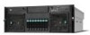
front bezel allow the system status LEDs to be monitored when the front bezel is closed. The front bezel is removable to allow access to server's hard drives, peripheral device, and control panel. For details on how to remove the front bezel, see "To remove the front bezel" on page 41 - Acer Altos R920 | User Manual - Page 27
9 Front panel A B CD E F G F Item A B C Icon Component DVD drive bay 5.25-inch drive bays VGA/monitor port D USB 2.0 ports E Control panel F Hot-swap system fan modules G Hot-plug HDDs - Acer Altos R920 | User Manual - Page 28
AC input power connector I/O expansion module (optional) Gigabit LAN ports (10/100/1000 Mbps) System ID button System ID indicator * Reserved for remote management of server. This requires installation of an ARMC/3 R2 module. - Acer Altos R920 | User Manual - Page 29
11 Internal components Item A B C D E F Component DVD drive bay Processor air baffle Memory board Plastic PCI slot divider and PCI slots Rear system fan modules Mainboard - Acer Altos R920 | User Manual - Page 30
12 System boards 1 System tour Mainboard The mainboard becomes accessible once you open the system. It should look like the figure shown below. D A B C EF G H I JK L M CC BB AA Z N Y X O W P V Q U T S R Item Description Item Description A Dual Ethernet ports P Front panel - Acer Altos R920 | User Manual - Page 31
Express x8 (slot 2) J Hot-plug PCI Express x8 (slot 1) K Serial port B L VGA port M USB 1 (top) USB 2 (bottom) N Memory board slot A O Memory board slot B * Reserved for tape drives. Item Description R CPU socket 1 S CPU socket 2 T CPU socket 3 U CPU socket 4 V SAS module - Acer Altos R920 | User Manual - Page 32
14 1 System tour Memory board The memory board connects to the mainboard through x16 PCI Express slots. HF IG DB ECA Q P O N M L K J Item Description A Power good indicator B DIMM 1 fault indicator C DIMM 2 fault indicator D - Acer Altos R920 | User Manual - Page 33
15 Control panel The Altos R920 system supports either the button control panel, providing basic functionality, or the LCD control panel, which adds additional server management features. Both control panels utilize a combination of control buttons, status LED indicators, along with I/O ports, to - Acer Altos R920 | User Manual - Page 34
16 Button control panel 1 System tour Item A Icon Component HDD (hard disk drive) activity indicator B LAN1 status indicator displays network activity in either LAN . C Status/fault indicator D Power indicator E System ID indicator F System ID button G Power button H Reset button - Acer Altos R920 | User Manual - Page 35
network activity in either LAN ports on the mainboard. LAN2 status indicator displays network activity in either LAN ports on the optional I/O expansion module. HDD (hard disk drive) activity indicator Reset button - Acer Altos R920 | User Manual - Page 36
button Back button Select button Function Puts the server in a halt-state for diagnostic purposes and allows you to issue a non-maskable interrupt. After using the interrupt, a memory download can be performed to determine the cause of the problem. Reboots and initializes the system. Toggles the - Acer Altos R920 | User Manual - Page 37
19 System LED indicators This section describes the different LED indicators located on • Control panel • Hot-plug HDD carrier • Hot-swap fan module • Hot-plug power supply module • LAN port • Hot-plug PCI Express slot • Memory board - Acer Altos R920 | User Manual - Page 38
20 Control panel LED indicators 1 System tour The following table list and describe the LED indicators available on the mini or optional full-function control panel. Item LED indicator Color A HDD Green activity LED status On System status - Green Blinking - Amber On - Amber Slow - - Acer Altos R920 | User Manual - Page 39
21 Item LED indicator Color LED status System status Description B LAN1, Green On LAN2 status • LAN1 active • LAN2 active • Network activity in either LAN ports on the mainboard. • Network activity in either LAN ports on the optional I/O expansion module. Green Blinking Active Network - Acer Altos R920 | User Manual - Page 40
22 1 System tour Item LED indicator Color D Power - Green - Green Green E System ID Blue - LED status Off System status Power off On Power on Off S4/S5 Blinking S1 On S0 On - Off - Description System is not powered on. System has power applied to it. System in ACPI S4 or - Acer Altos R920 | User Manual - Page 41
23 Item B Color Green Status On Flashing Off Description HDD is installed and working correctly. HDD is active. • No HDD is installed. • HDD is initiated but has no current activity. Hot-swap fan module LED indicators LED indicator Fan good Fan fault Color - Amber Status Description Off - Acer Altos R920 | User Manual - Page 42
24 1 System tour Hot-plug power supply module LED indicators Item LED indicator Color A Power good Green B Fault Amber C AC OK Green Status Description On System has power applied to it. On • Power rail failure. • Power supply is in a latched state. On AC power cord is plugged - Acer Altos R920 | User Manual - Page 43
25 LAN port LED indicators AB Item A B LED indicator Color Status Description Status Green On Network link is detected. Off No network connection. Blinking Network connection in place. Speed - Off 10 Mbps connection Green On 100 Mbps connection Amber On 1000 Mbps connection Hot- - Acer Altos R920 | User Manual - Page 44
Status Normal Attention Locate Description Normal operation Power failure or operational problem at the slot. Slot is being identified. Memory board LED indicators The LEDs on the memory board indicate the status of the memory board power and DIMM. HF IG DB ECA Item A B-I LED indicator - Acer Altos R920 | User Manual - Page 45
27 System jumpers AC D B EF Item Name A Rolling BIOS B Password disable or clear C Clear CMOS/ NVRAM D BMC force update Location Default J3D1 1-2 (Empty) 2-3 (Stuff) J3C2 1-2 (Stuff) 2-3 (Empty) J3C3 1-2 (Stuff) 2-3 (Empty) J5C1 1-2 (Stuff) 2-3 (Empty) Settings Force other - Acer Altos R920 | User Manual - Page 46
28 1 System tour Item Name Location Default E BMC flash write J6D1 protect 1-2 (Stuff) 2-3 (Empty) F Circuit breaker J6F1 1-2 (Empty) 2-3 (Stuff) Settings Disable flash write protect Enable flash write protect 20 A/110 V (USA) 15 A/100 V (Japan) - Acer Altos R920 | User Manual - Page 47
2 System setup - Acer Altos R920 | User Manual - Page 48
This chapter gives you instructions on how to set up the system. Procedures on how to connect peripherals are also explained. - Acer Altos R920 | User Manual - Page 49
, radio and TV transmitters, etc. Checking the package contents Check the following items from the package: • Acer Altos R920 system • Acer EasyBUILDTM • Acer eBusiness ValuePack • Acer Altos R920 accessory box If any of the above items are damaged or missing, contact your dealer immediately. Save - Acer Altos R920 | User Manual - Page 50
32 2 System setup Connecting peripherals Refer to the illustration below for specific connection instructions on the peripherals you want to connect to the system. 110/220 V 110/220 V Note: Consult the operating system manual for information on how to configure the network setup. - Acer Altos R920 | User Manual - Page 51
power on the system. 1 Remove the front bezel. 2 Press the power button. 3 The system starts up and displays a welcome message on the monitor. After that, a series of power-on self-test (POST) messages appear. The POST messages indicate if the system is running well or not. - Acer Altos R920 | User Manual - Page 52
power indicator on the control panel lights up green. • The Num Lock, Caps Lock, and Scroll Lock indicators on the keyboard light up. Power-on problems If the system does not boot after you have applied power, check the following factors that might have caused the boot failure. • The external power - Acer Altos R920 | User Manual - Page 53
35 Configuring the system OS The Altos R920 system comes with Acer EasyBUILD that allows you to conveniently install your choice of operating system. To start using EasyBUILD, follow the steps below. 1 Locate the EasyBUILD DVD included in the system package. 2 With the system turned on, gently press - Acer Altos R920 | User Manual - Page 54
36 2 System setup Turning off the system There are two ways to turn off the server-via software or via hardware. The software procedure below applies to a system running on a Windows OS. For other OS shutdown procedures, refer to the related - Acer Altos R920 | User Manual - Page 55
3 System upgrade - Acer Altos R920 | User Manual - Page 56
This chapter discusses the precautionary measures and installation procedures you need to know to upgrade the system. - Acer Altos R920 | User Manual - Page 57
ESD precautions along with pre-installation and post-installation instructions. ESD precautions Electrostatic discharge (ESD) can damage the processor, disk drives, expansion boards, motherboard, memory modules and other server components. Always observe the following precautions before you install - Acer Altos R920 | User Manual - Page 58
a flat, stable surface. 5 Open the system according to the instructions on page 41. 6 Follow the ESD precautions described in this section when handling a server component. Post-installation instructions Perform the steps below after installing a server component. 1 See to it that all components are - Acer Altos R920 | User Manual - Page 59
proceed, make sure that you have turned off the system and all peripherals connected to it. Read the "Preinstallation instructions" section on page 40. You need to open the server before you can install additional components. The front bezel and top cover are removable to allow access to the system - Acer Altos R920 | User Manual - Page 60
42 To install the front bezel: Slide the front bezel onto the chassis. 3 System upgrade - Acer Altos R920 | User Manual - Page 61
Removing and installing the top cover To remove the top cover: 1 Perform the pre-installation instructions described on page 39. 2 Loosen the two captive screws located on the faceplate of slots on the chassis. 4 Lift the top cover away from the server and put it aside for reinstallation later (B). - Acer Altos R920 | User Manual - Page 62
44 3 System upgrade To install the top cover: 1 Perform the pre-installation instructions described on page 39. 2 Place the top cover on the chassis so that the tabs on the cover align with the slots on the chassis (A). 3 - Acer Altos R920 | User Manual - Page 63
the SAS module • Removing and installing the RAID activation key and RAID cache • Removing and installing the RAID BBU 1 Perform the pre-installation instructions described on page 39. 2 Disconnect the 100-pin cable from the mainboard connector on the front panel I/O board then move cable over the - Acer Altos R920 | User Manual - Page 64
46 3 System upgrade To install the processor air baffle: 1 Perform the pre-installation instructions described on page 39. 2 Insert the front of the processor air baffle (A) under the two metal tabs at the front of the baffle (B), just below - Acer Altos R920 | User Manual - Page 65
3 Lower the rear of the baffle into place (A), making sure the guides on each side of the air baffle will correctly engage in the left and right chassis slots (B). A A B A B B 4 Push down the air baffle to ensure it is fully seated. 5 Observe the post-installation instructions described on page 40. - Acer Altos R920 | User Manual - Page 66
Configuring hot-pluggable components Hot-pluggable components are the components that can be removed and replaced while the system is powered on. For this server model, it refers to the following components. • Hard disk drive • System fan assembly • Power supply • PCI card with OS hot-plug interface - Acer Altos R920 | User Manual - Page 67
hard disk drive The system supports eight hot-plug drive carriers. Each carrier holds a standard 2.5-inch SAS hard drive. Note: Use only Acer-qualified HDDs. To purchase an HDD, contact your local Acer representative. Caution! To ensure proper airflow and server Perform the instructions described in - Acer Altos R920 | User Manual - Page 68
, remove the four screws that secure the hard disk to the HDD carrier, then remove the disk from the HDD carrier. 8 Keep the screws for later HDD installation. To install an HDD: Note: To purchase an HDD carrier, contact your local Acer representative. 1 Perform steps 1 through 5 of the "To remove - Acer Altos R920 | User Manual - Page 69
the air baffle from the HDD carrier (B). 4 Save the air baffle and screws for later use. 5 Remove the HDD from its protective packaging. 6 Install a hard disk on the HDD carrier, then secure it with the four screws (A) that came with the HDD carrier (B). B A 7 With the lever still extended, slide - Acer Altos R920 | User Manual - Page 70
lever to push the HDD carrier until it docks into place, then close the HDD carrier lever (B). A B 9 Setup the new hard drive's RAID configuration. For related instructions, refer to "RAID configuration utilities" on page 177. Removing and installing the system fan The system has two cooling fan - Acer Altos R920 | User Manual - Page 71
during normal operation. To remove the front system fan assembly: 1 Observe the ESD precautions described on page 39. 2 Remove the front bezel. Perform the instructions described in "To remove the front bezel" section on page 41. 3 Locate the fan assembly you are replacing. If a fan in the assembly - Acer Altos R920 | User Manual - Page 72
54 3 System upgrade 3 Push the handle closed until it clicks into place (B). To remove a rear system fan: 1 Perform the pre-installation instructions described on page 39. 2 Locate the fan assembly you are replacing. If a fan in the assembly has failed the amber LED will be lit. 3 Grasp - Acer Altos R920 | User Manual - Page 73
55 To install a rear system fan: Warning! To ensure proper system cooling, the replacement of a failed system fan module should be completed within one minute. 1 If necessary, remove the old rear system fan. See previous section. 2 Lower the new fan into the fan bay. 3 Push down on the fan until it - Acer Altos R920 | User Manual - Page 74
of personal injury or damage to the equipment, the installation of power supply modules should be referred to individuals who are qualified to service server systems and are trained to deal with equipment capable of generating hazardous energy levels. WARNING! To reduce the risk of personal injury - Acer Altos R920 | User Manual - Page 75
57 To remove a power supply: Caution: Power supply hot-swap operations should be performed only if a failure occurs in the power supply. 1 Observe the ESD precautions described on page 39. 2 Remove the AC power cord from the power supply. 3 Press down on the latch to release the power supply handle - Acer Altos R920 | User Manual - Page 76
58 3 System upgrade To install a power supply: 1 If necessary, remove the old power supply. See previous section. 2 With the handle in the open position, push the power supply in the bay fully (A). 3 Rotate the handle to the closed position (B). 4 Tighten the thumbscrew to secure the power supply - Acer Altos R920 | User Manual - Page 77
vacant slots to maintain the electromagnetic emission characteristics of the server and to ensure proper system cooling. Determining PCI slot status plug PCI card with OS hot-plug interface: 1 Perform the pre-installation instructions described on page 39. 2 If you are using a Microsoft Windows - Acer Altos R920 | User Manual - Page 78
in an antistatic protective wrapper. 9 If installing a new PCI card, see "To install a new PCI hot-plug PCI card" section. 10 Observe the post-installation instructions described on page 40. To remove a hot-plug PCI card with hardware interface: 1 Perform the pre-installation - Acer Altos R920 | User Manual - Page 79
card in an antistatic protective wrapper. 8 If installing a new PCI card, see "To install a new PCI hot-plug PCI card" section. 9 Observe the post-installation instructions described on page 40. - Acer Altos R920 | User Manual - Page 80
62 3 System upgrade To install a new hot-plug PCI card: 1 If your server is operating, use your OS to power down the PCI slot. 2 Perform the pre-installation instructions described on page 39. 3 Open the yellow caution plate (A). 4 Rotate the slot retention latch on the rear of the card slot - Acer Altos R920 | User Manual - Page 81
to be powered down before you can remove or replace them. The cold-pluggable components installed in the server include. • DVD drive • 5.25-inch drive • Processor • Memory board assembly • DIMM module • PCI card • I/O expansion module • ARMC/3 R2 module • SAS module • RAID activation key and RAID - Acer Altos R920 | User Manual - Page 82
64 3 System upgrade Removing and installing the DVD drive To remove the DVD drive: 1 Perform the pre-installation instructions described on page 39. 2 Disconnect the power and SATA cables from the SATA-to-IDE converter board on the rear of the media device (A). 3 Press - Acer Altos R920 | User Manual - Page 83
65 7 Observe the post-installation instructions described on page 40. To install the DVD drive: 1 Perform the pre-installation instructions described on page 39. 2 If necessary, remove the old DVD drive. See previous section. 3 Remove the new drive from its protective packaging. 4 Attach the SATA-to - Acer Altos R920 | User Manual - Page 84
bay allows you to install a tape drive to provide the system with additional storage capacity. To install a 5.25-inch drive: 1 Perform the pre-installation instructions described on page 39. 2 Push the tabs on both sides of the carrier filler panel (A). 3 Hold the tabs in while pulling the carrier - Acer Altos R920 | User Manual - Page 85
67 7 Slide the 5.25-inch peripheral device into the server until it clicks into place. 8 Observe the post-installation instructions described on page 40. - Acer Altos R920 | User Manual - Page 86
server supports up to four processors, the following models are supported. • Quad-core Intel Xeon processors 7300 series • Dual-core Intel Xeon processors 7200 series . To install a new processor: 1 Perform the pre-installation instructions described on page 39. Warning! The heat sink becomes very - Acer Altos R920 | User Manual - Page 87
3 Remove the thermal blank. (1) Loosen the four screws on the thermal blank. (2) Pull the thermal blank away from the CPU socket. TheBrmlaanlk Server Board Cutaway (3) Store the thermal blank in a protective bag. 4 Remove the new processor from its protective packaging. 5 Install the new processor - Acer Altos R920 | User Manual - Page 88
70 3 System upgrade (2) Position the processor over the socket, matching the two triangle markers (A) and lining up the processor pins with the socket (B). (3) Press the retainer lever down to lock the processor in place. 6 Apply thermal grease. Apply approximately 0.1 ml of the thermal grease - Acer Altos R920 | User Manual - Page 89
the system is on. NEVER touch the heat sink with any metal or with your hands. 2 If necessary, remove the processor air baffle. Perform instructions described in "To remove the processor air baffle" section on page 45. 3 If a heatsink is installed, remove the heat sink. (1) Loosen the four screws - Acer Altos R920 | User Manual - Page 90
72 3 System upgrade (2) Pull the heat sink away from the CPU socket. 3 1 2 4 (3) Lay down the heat sink in an upright position-with the thermal patch facing upward. Do not let the thermal patch touch the work surface. (4) Use an alcohol pad to wipe off the thermal grease from both the heat - Acer Altos R920 | User Manual - Page 91
are not installing a new processor, reinstall the processor thermal blank to maintain proper airflow within the chassis. 6 If you going to install a new processor, perform instructions described in "To install a new processor" section. 7 Observe the post-installation - Acer Altos R920 | User Manual - Page 92
74 3 System upgrade Removing and installing a memory board assembly The server supports up to four memory boards. At least one memory board and two FBDIMMs must be installed for the server to function. Each memory board supports eight DIMM slots and a DIMM fault LED for each FBDIMM that is used to - Acer Altos R920 | User Manual - Page 93
75 2 Lift the latches on the memory board to disengage the memory board from the mainboard (A). 3 Lift the memory board by the latches (B). B A 4 Observe the post-installation instructions described on page 40. - Acer Altos R920 | User Manual - Page 94
upgrade To install the memory board assembly: 1 Perform the pre-installation instructions described on page 39. 2 Locate an empty memory board slot. 3 Add or replace memory DIMMs as needed. For instructions, see "Installing and removing DIMM modules" section. 4 Lift the memory board latches to the - Acer Altos R920 | User Manual - Page 95
the following guidelines when replacing or installing DIMM modules to the memory boards. • The system supports up to four memory boards. At least one memory board and two DIMMs must be installed for the server to function. Each memory board must have a minimum of two DIMMs installed. • DIMMs must be - Acer Altos R920 | User Manual - Page 96
. Important: DIMM thermal blanks must be installed to empty DIMM slots to ensure proper system thermal performance. Memory Board SSSSSSSSoooooooocccccccckkkkkkkkeeeeeeeetttttttt 8 7 6 5 4 3 2 1 FBDIMM • FBDIMMs should be identical in terms of timing, technology, and size. Note: For additional - Acer Altos R920 | User Manual - Page 97
to installation sequence. DIMMs may be installed in pairs. 1 Perform the pre-installation instructions described on page 39. 2 Remove the memory board assembly. Perform the instructions described in "To install the memory board assembly" section on page 76. 3 Remove the DIMM cover from the - Acer Altos R920 | User Manual - Page 98
Line up the hooks in the cover with the notches on the bottom edge of the memory board. (3) Press the DIMM cover down until it clicks into place. 10 Install the memory board assembly. For instructions, see "To install the memory board assembly" section on page 76. 11 Observe the post-installation - Acer Altos R920 | User Manual - Page 99
to remove it from the socket. 4 Install the memory board assembly. For instructions, see "To install the memory board assembly" section on page 76. 5 Observe the post-installation instructions described on page 40. To reconfigure the system memory: The system automatically detects the amount of - Acer Altos R920 | User Manual - Page 100
card from one of these slots, you can do so without powering down the server. For information, refer to page 59. To remove a non-hot-plug PCI removal or installation of non-hot-plug boards. 1 Perform the pre-installation instructions described on page 39. 2 Disconnect any cables attached to the PCI - Acer Altos R920 | User Manual - Page 101
83 Configuring server management components Altos R920 system provides an upgrade path to advanced server management capabilities through ports. To install the I/O expansion module: 1 Perform the pre-installation instructions described on page 39. 2 Rotate the retention latch on the rear of - Acer Altos R920 | User Manual - Page 102
84 3 System upgrade 6 Insert the module into the I/O expansion module slot on the mainboard. Make sure that the card is properly seated (D). B A C D 7 Rotate the retention latch downward. 8 Observe the post-installation instructions described on page 40. - Acer Altos R920 | User Manual - Page 103
85 To remove the I/O expansion module: 1 Perform the pre-installation instructions described on page 39. 2 Rotate the retention latch on the rear of the I/O expansion module slot upward (A). 3 Pull the board away from the chassis (B). B A 4 Store - Acer Altos R920 | User Manual - Page 104
upgrade Installing and removing the ARMC/3 R2 module The optional ARMC/3 R2 module provides server management firmware and functionality for the system. To install the ARMC/3 R2 module: 1 Perform the pre-installation instructions described on page 39. 2 Remove the I/O expansion module. Perform - Acer Altos R920 | User Manual - Page 105
on the I/O expansion module and snap the standoff into the matching hole on the I/O module (B). Network ARNMICC/3 I/O Expansion A Module ARMC/3 A B 9 Install the I/O expansion module. Perform instructions described on "To install the I/O expansion module" section. - Acer Altos R920 | User Manual - Page 106
described on page 40. To remove the ARMC/3 R2 module: 1 Perform the pre-installation instructions described on page 39. 2 Remove the I/O expansion module. Perform instructions described in "To remove the I/O expansion module" section on page 85. 3 Set the I/O expansion module on a static - Acer Altos R920 | User Manual - Page 107
89 Configuring the hardware RAID components Altos R920 system supports SAS hardware RAID through installation support eight SAS hard drives. The SAS module supports RAID levels 0, 1, 1a, and 10 without any additional components. To install the SAS module: 1 Perform the pre-installation instructions - Acer Altos R920 | User Manual - Page 108
90 3 System upgrade 5 Align then insert the SAS module in the SAS module slot on the mainboard. Make sure that the edge of the card is properly seated (A). 6 Press down on the card until the metal bracket on the card is flush with the chassis (B) and locks into place (C). A C B - Acer Altos R920 | User Manual - Page 109
SAS connector A (A) and the SAS connector B (B) on the adapter. 8 Attach the SES cable to the SES connector on the SAS module (C). C B A 9 Observe the post-installation instructions described on page 40. To remove the SAS module: 1 Perform the pre-installation - Acer Altos R920 | User Manual - Page 110
92 3 System upgrade 3 Disconnect any cables attached to the SAS module. 4 While pushing back on the slot divider latch, pull the SAS module away from the chassis. 5 Store the card in an antistatic bag. 6 Observe the post-installation instructions described on page 40. - Acer Altos R920 | User Manual - Page 111
enhanced RAID functionality on the SAS module. The RAID cache serves as memory for the SAS controller, and as a disk cache to store write cache: 1 Perform the pre-installation instructions described on page 39. 2 Remove the processor air baffle. Perform instructions described in "To remove the - Acer Altos R920 | User Manual - Page 112
94 3 System upgrade To remove the RAID activation key and RAID cache: 1 Perform the pre-installation instructions described on page 39. 2 Remove the processor air baffle. Perform instructions described in "To remove the processor air baffle" section on page 45. 3 Remove the SAS module. Perform - Acer Altos R920 | User Manual - Page 113
, maintaining the integrity of the disk array. To install the RAID BBU: 1 Perform the pre-installation instructions described on page 39. 2 Remove the processor air baffle. Perform instructions described in "To remove the processor air baffle" section on page 45. 3 Remove the SAS module. Perform - Acer Altos R920 | User Manual - Page 114
described in "To remove the processor air baffle" section on page 45. 3 Remove the SAS module. Perform instructions described in "To remove the SAS module" section on page 89. 4 Remove the three screws on the RAID BBU. 5 Remove the RAID BBU from the - Acer Altos R920 | User Manual - Page 115
4 System BIOS - Acer Altos R920 | User Manual - Page 116
This chapter gives information about the system BIOS and discusses how to configure the system by changing the settings of the BIOS parameters. - Acer Altos R920 | User Manual - Page 117
loads the configuration values in a battery-backed nonvolatile memory called CMOS RAM. This memory area is not part of the system RAM which "Setup", "System BIOS" or "Setup Utility" in this guide. The screenshots used in this guide display default system values. These values may not be the same - Acer Altos R920 | User Manual - Page 118
. BIOS setup menus There are several tabs on the setup screen corresponding to the eight primary BIOS menus. • Main • Advanced • Security • Server Management • Boot Options • Boot Manager • Error Manager • Exit In the descriptive table following each of the screen illustrations, settings in boldface - Acer Altos R920 | User Manual - Page 119
101 BIOS setup keyboard commands Use the following commands to navigate through the Setup Utility. • Left and Right arrow keys - Move between selections on the menu bar. • Up and Down arrow keys - Move the cursor to select an item. • + and - keys - Press the keys to scroll through drop down list - Acer Altos R920 | User Manual - Page 120
menu The Main menu displays basic and important information about the system. These information are necessary for troubleshooting and may be required when asking for technical support. These entries are for your reference only and are not user-configurable. Parameter Logged in as - Acer Altos R920 | User Manual - Page 121
Type Core Frequency Count Specification of the processor currently installed in the server. Processor clock speed in GHz or MHz. Number of processors currently installed in the server. Memory Size Total size of system memory detected during POST. Quiet Boot When enabled, the BIOS splash screen - Acer Altos R920 | User Manual - Page 122
104 4 System BIOS Advanced menu The Advanced menu display submenu options for configuring the function of various hardware components. Select a submenu item, then press Enter to enter to access the related submenu screen. - Acer Altos R920 | User Manual - Page 123
105 Processor Configuration Parameter Description Option Core Frequency Frequency at which the processors currently run in. System Bus Frequency Frequency of the processor front side bus. Enhanced Intel SpeedStep Tech When enabled, this feature allows the OS to reduce power consumption. When - Acer Altos R920 | User Manual - Page 124
to eliminate the error message. Enabled Disabled Processor Information Displays information about the system processor, such as family or generation, frequency supported, cache size, stepping number, and processor ID register value. Press Enter to access the Processor # Information submenu. - Acer Altos R920 | User Manual - Page 125
Total Memory Effective Memory Description Total amount of onboard memory in MB or GB. The memory size is automatically detected by BIOS during the POST. If you install additional memory, the system automatically adjusts this parameter to display the new memory size. Amount of memory available - Acer Altos R920 | User Manual - Page 126
enabled. Current Displays the speed the memory is currently running at 533 Memory Speed MT/s (266 MHz) or 667 MT/s (333 MHz). Memory RAS and Performance Configuration Customize several memory configuration options, such as whether to use memory mirroring or memory sparing. Press Enter to access - Acer Altos R920 | User Manual - Page 127
Mirroring Possible Indicates if system memory is configured Yes/No for memory mirroring. Memory Indicates if system memory is configured Yes/No Sparing Possible for memory sparing. Select Memory RAS Configuration Provides options for configuring Memory RAS. The possible options for this menu - Acer Altos R920 | User Manual - Page 128
System BIOS Parameter Snoop Filter FSB High Bandwidth Optimization Description The Snoop Filter component monitors and controls the data transactions between memory and the processor. Enables or disables optimize front side bus for higher bandwidth when 1333 MHz FSB processor(s) is installed. Note - Acer Altos R920 | User Manual - Page 129
ROM Enables or disables the onboard SAS controller option ROM. Enabled Disabled SATA Mode When set to IDE, system supports up to 4 SATA ports with Parallel ATA emulation. When set to AHCI, system supports all SATA ports using the Advanced Host Controller interface. When set to SW RAID, system - Acer Altos R920 | User Manual - Page 130
112 Serial Port Configuration 4 System BIOS Parameter Description Option Serial A Enable Enables or disables the onboard serial A port. Enabled Disabled Address Set the base I/O address for serial A port. 3F8 2F8 2E8 3E8 IRQ Set the interrupt request line for the serial 4 A port. 3 - Acer Altos R920 | User Manual - Page 131
Option Set the interrupt request line for the serial 3 B port. 4 USB Configuration Parameter Detected USB Devices USB Controller Legacy USB Support Description Indicates the number of USB devices. Option When enabled, all onboard USB controllers will be turned on and accessible by the OS - Acer Altos R920 | User Manual - Page 132
Reset Timeout Storage Emulation RMM USB 2.0 Controller Description Option Enables or disables the I/O port 60/64h emulation support. This parameter is enabled for complete USB keyboard legacy support USB ports to support USB 2.0 mode. Auto Floppy Forced FDD Hard Disk CD-ROM Enabled Disabled - Acer Altos R920 | User Manual - Page 133
on the system configuration, this option may impact the amount of system memory detected by an OS without Physical Address Extension (PAE) support. 2.00 GB 2.25 GB 2.50 GB 1.50 GB 1.75 GB Memory Mapped I/O Above 4 GB Enables or disables memory mapped I/O of 64-bit PCI devices to 4 GB or greater - Acer Altos R920 | User Manual - Page 134
116 4 System BIOS Parameter Dual Monitor Video Slot ROM Description Option Select a graphic controller as a primary boot device. Note: This parameter will be disabled when the Onboard Video is set to Disabled. Enabled Disabled Controls execution of the add-in adapter option ROM during - Acer Altos R920 | User Manual - Page 135
onboard LAN's I/O Acceleration Technology. The I/O AT accelerates TCP/IP processing for onboard NICs, delivers data movement efficiencies across the entire server platform and minimizes system overhead. Enabled Disabled Onboard NIC1 or NIC2 ROM Enables or disables the load of embedded option ROM - Acer Altos R920 | User Manual - Page 136
118 4 System BIOS Parameter Description Option I/O Riser Board NIC ROM Load the embedded option ROM for the I/O expansion module network controllers. Note: If disabled, the I/O expansion module (NIC1 and NIC2) cannot be used to boot or wake the system. Enabled Disabled I/O Riser Board NIC1 - Acer Altos R920 | User Manual - Page 137
119 System Acoustic and Performance Configuration Parameter Throttling Mode Description Option Closed loop allows the system to achieve higher performance by monitoring system temps and adjusting bandwith. Open loop does not rely on a thermal sensor on the board and sets up a static level which - Acer Altos R920 | User Manual - Page 138
120 4 System BIOS Security menu The Security menu allows you to safeguard and protect the system from unauthorized use by setting up access passwords. Parameter Description Option Administrator Password Status Indicates the status of the administrator password. User Password Indicates the - Acer Altos R920 | User Manual - Page 139
121 Parameter Description Option Front Panel Lockout When enabled, the front panel power and reset buttons will be locked. The power and reset operation must be controlled via system management interface. Enabled Disabled TPM State Shows the current state of the Trusted Platform Module (TPM) - Acer Altos R920 | User Manual - Page 140
122 4 System BIOS Changing a system password 1 Use the up/down keys to highlight either change password parameters (Set Administrator Password or Set User Password) then press Enter. 2 Type the original password then press Enter. 3 Type a new password then press Enter. 4 Retype the password to - Acer Altos R920 | User Manual - Page 141
Management menu The Server Management submenu lets you specify the appropriate settings for the it was prior to the AC power loss. When set to Reset, the system will turn on after power is restored. Stay Off Last state Reset Clear System Event Log Deletes all entries in the System Event Log - Acer Altos R920 | User Manual - Page 142
system powers off if the watchdog timer expires. When set to Reset, the system performs a reset if the watchdog timer expires. Note: The OS Boot Watchdog Timer must be enabled at the same time. Power Off Reset OS Boot Timeout value BIOS will use to configure the Watchdog - Acer Altos R920 | User Manual - Page 143
125 Console Redirection Parameter Console Redirection Description Define the serial port used for server management tasks. Flow Control* Set hardware flow control. Baud Rate* Set the serial port transmission speed. Terminal Type* Set character formatting used for console redirection. - Acer Altos R920 | User Manual - Page 144
126 4 System BIOS Parameter Description Option Legacy OS Redirection* Enables or disables the legacy OS redirection (i.e. DOS) on the serial port. If it is enabled the associated serial port is hidden from the legacy OS. Enabled Disabled * These fields are not shown on the above screenshot. - Acer Altos R920 | User Manual - Page 145
127 System Information The System Information submenu displays basic information about the server unit. - Acer Altos R920 | User Manual - Page 146
128 4 System BIOS Intel Remote Management Module Information The Remote Management Module submenu displays information about the firmware revisions and network devices. - Acer Altos R920 | User Manual - Page 147
129 Boot Options menu The Boot Options menu allows you to set the network device priority during system bootup. It also displays information about the installed storage devices. Parameter Description Option Boot Timeout Sets the automatic boot time-out value. Note: A value of 65535 will disable - Acer Altos R920 | User Manual - Page 148
130 4 System BIOS Boot Manager menu The Boot Manager menu lets you set the device priority during system bootup. The server will attempt to boot from the first device on the list. If the first device is not available, it will continue down the list until - Acer Altos R920 | User Manual - Page 149
131 Error Manager menu The Error Manager menu lets you view the system POST errors detected by the system. Parameter Error Code Severity Instance Description Attribute Displays the POST error beep codes. Major severity requires user intervention but does not stop system boot. Minor severity do - Acer Altos R920 | User Manual - Page 150
Loads the default settings for all BIOS setup parameters. Setup defaults are quite demanding in terms of resources consumption. If you are using low-speed memory chips or other kinds of low-performance components and you choose to load these settings, the system might not function properly. - Acer Altos R920 | User Manual - Page 151
133 Parameter Description Save as User Default Values Saves current values to be restored later. Load User Default Values Restores previously saved user default values. - Acer Altos R920 | User Manual - Page 152
file to a temporary folder on your hard drive or a USB flash memory device. Note: Review the instructions and release notes that are provided in . The system will reset automatically when the BIOS update process is completed. You may encounter a CMOS checksum error or other problem after reboot. It - Acer Altos R920 | User Manual - Page 153
5 System troubleshooting - Acer Altos R920 | User Manual - Page 154
This chapter provides possible solutions for specific problems. If you cannot correct the problem, contact your local Acer representative or authorized dealer for assistance. - Acer Altos R920 | User Manual - Page 155
your server problems on your own, contact your dealer or local Acer representative for assistance. Resetting the system Before going through in-depth troubleshooting, attempt first to perform reset the system using one of the methods below. To do this Soft boot reset to clear the system memory and - Acer Altos R920 | User Manual - Page 156
troubleshooting installed correctly? • If the system has a hard disk drive, is it properly formatted or configured? power button on the front panel to turn the server on (power indicator should be lit)? • Is the memory, and chassis lists, as well as the supported hardware and operating system list. - Acer Altos R920 | User Manual - Page 157
provides a more detailed approach to identifying a hardware problem and locating its source. Caution! Before disconnecting any supplied with your video display monitor). 4 If the operating system normally loads from the hard disk drive, make sure there is no disc in the optical drive. 5 If the - Acer Altos R920 | User Manual - Page 158
troubleshooting Specific problems and corrective actions The following contains specific problems that may arise during the use of your server. Possible solutions are listed for each problem sure the memory board and memory modules comply with the system requirements. • Make sure the memory modules - Acer Altos R920 | User Manual - Page 159
• Check the BIOS release notes to ensure the BIOS installed on the platform supports the stepping and the family of processors currently installed. • Make sure the memory boards are populated according to system requirements. Server does not recognize all of the processors installed. • Make sure the - Acer Altos R920 | User Manual - Page 160
System troubleshooting • disc is unscratched. • Make sure all cables are connected to the ODD. Hard drives are not recognized. • Make sure the drive is not disabled in Make sure that you have not exceeded the power budget for the server. Bootable CD drive is not detected. • Make sure the Boot - Acer Altos R920 | User Manual - Page 161
connect to a server. • Make sure the network cable is securely attached to the correct connector at the system rear panel. • Try a different network cable. • Make sure you are using the correct and the current drivers. • Make sure the driver is loaded and the protocols are bound. Problems with the - Acer Altos R920 | User Manual - Page 162
. Server hangs when the drivers are loaded. • Change the PCI interrupt settings. There is problem with the application software. Do the following: • Verify that the software is properly configured for the system. Refer to the software installation and operation documentation for instructions on - Acer Altos R920 | User Manual - Page 163
a different version of the software to see if the problem is with the copy you are using. • Make sure with a reboot between each addition. • Make sure the memory modules comply with the system requirements. • Make sure the memory modules have been populated according to the system requirements. • - Acer Altos R920 | User Manual - Page 164
System troubleshooting the beep code you hear. This information is useful for your service representative. 5 If you do not receive a beep code and panel LEDs lit? • Have any of the fan motors stopped? Use the server management subsystem to check the fan status. • Have your fans speeded up - Acer Altos R920 | User Manual - Page 165
147 • Is the fan's power connector properly connected to the mainboard? • Is the front panel board cable connected to both the mainboard's front panel board connector? • Are the power supply cables properly connected to the mainboard? • Are there any shorted wires caused by pinched cables or have - Acer Altos R920 | User Manual - Page 166
148 5 System troubleshooting - Acer Altos R920 | User Manual - Page 167
Appendix A: Rack mount configuration - Acer Altos R920 | User Manual - Page 168
This appendix shows you how to set up the Altos R920 system in a rack mount configuration. - Acer Altos R920 | User Manual - Page 169
equipment rack The equipment rack must be anchored to an unmovable suitable support to prevent the rack from falling over when one or more assembly. The equipment rack must be installed according to the manufacturer's instructions. • Main AC power disconnect You are responsible for installing an - Acer Altos R920 | User Manual - Page 170
152 Appendix A: Rack mount configuration • Elevated operating ambient temperature The maximum operating temperature of the system is 35 °C (95°F). Careful consideration should be given to installing the system in an environment compatible with the 35 °C (95°F) maximum ambient temperature. • - Acer Altos R920 | User Manual - Page 171
153 Rack mount configuration The Altos R920 server system should be mounted into a rack cabinet. A rack rail and CMA (cable management arm) kit is available for installing system to a rack cabinet. The figure below shows the Altos R920 system in a rack-mount position. - Acer Altos R920 | User Manual - Page 172
of two holes with closer spacing to the center of the next pair is equivalent to 1U. Note: The unit of measurement used in this guide is "U" (1U = 1.75 inches or 44.45 mm). The total sum of the heights of all components in the rack measured in "U" cannot exceed the - Acer Altos R920 | User Manual - Page 173
155 Installing the system into the rack Caution! To minimize the chances of injuries, make sure that two or more people help in installing the server. To install the system into a four-post rack: 1 Remove the inner rails from the mounting rails. (1) Extend the inner rail from the mounting rail until - Acer Altos R920 | User Manual - Page 174
those supplied in this rack-mount kit to attach the rails will void the warranty, Acer cannot be held responsible for any damage for incorrect installation. (1) Align the screw holes of the inner rail to the server screws (A). (2) Slide the rails to the left until the rails lock into place with an - Acer Altos R920 | User Manual - Page 175
157 3 Install the mounting rails to the rack posts. (1) Determine the vertical position in the rack. Refer to "Vertical mounting hole pattern" on page 154 for more information. (2) Align and insert the mounting rail into the rack posts' mounting holes (A). (3) Make certain the proper mounting holes - Acer Altos R920 | User Manual - Page 176
158 Appendix A: Rack mount configuration (6) Fully extend the mounting rails on the rack. - Acer Altos R920 | User Manual - Page 177
should be taken when pressing the inner rail release latches and sliding the component into the rack. (1) Carefully align the inner rails attached to the server with the fully extended mounting rails on the rack. (2) Press the release latch on both sides of the - Acer Altos R920 | User Manual - Page 178
160 Appendix A: Rack mount configuration 5 Attach the CMA (cable management arm) to the rear of the server. The CMA allows you to tie-wrap all cables to and from the system. As you slide the system in and out of the rack, - Acer Altos R920 | User Manual - Page 179
161 (6) Connect the power, peripheral and networking cables into their appropriate ports. Refer to "Connecting peripherals" on page 32 for detailed instructions. (7) Route all cables through the cable clips. - Acer Altos R920 | User Manual - Page 180
162 Appendix A: Rack mount configuration - Acer Altos R920 | User Manual - Page 181
Appendix B: Memory configuration - Acer Altos R920 | User Manual - Page 182
This chapter provides details on how to configure the system memory boards. Recommended memory board and FBDIMM installation order and FBDIMM population order tables are also included. - Acer Altos R920 | User Manual - Page 183
The system's memory architecture supports up to four memory boards organized by branches and channels. The MCH (memory controller hub) on the north bridge has two branches with branch 0 going to channels 0 and 1 or memory board A and B, and branch 1 to channels 2 and 3 or memory board C and - Acer Altos R920 | User Manual - Page 184
slot, refer to "Mainboard" on page 12 for the location of the memory board slots.). Each memory board is equipped with eight DIMM slots that supports 1 GB, 2 GB, or 4 GB DDR2-667 MHz (PC-5300) FBDIMM modules. The memory board includes a DIMM fault LED that is used to report DIMM failures and - Acer Altos R920 | User Manual - Page 185
4 4 x 4 GB 16 GB 1 to 6 6 x 4 GB 24 GB 1 to 8 8 x 4 GB 32 GB Population with two memory boards DIMM slot Memory board A Memory board B Memory board C Memory board D Total memory 1 to 2 2 x 1 GB 2 x 1 GB 4 GB 1 to 4 4 x 1 GB 4 x 1 GB 8 GB 1 to 6 6 x 1 GB 6 x 1 GB 12 GB 1 to - Acer Altos R920 | User Manual - Page 186
configuration Population with four memory boards DIMM slot Memory board A Memory board B Memory board C Memory board D Total memory 1 to 2 2 x 1 GB 2 x 1 GB 2 x 1 GB 2 x 1 GB 8 GB 1 to 4 4 x 1 GB 4 x 1 GB 4 x 1 GB 4 x 1 GB 16 GB 1 to 6 6 x 1 GB 6 x 1 GB 6 x 1 GB 6 x 1 GB 24 - Acer Altos R920 | User Manual - Page 187
4 GB 64 GB 60 GB * DIMM slot 1 in memory boards A and B is configured to sparing mode. Population with four memory boards DIMM Memory board Memory board Memory board Memory board slot* A B C D Total memory Physical Detected memory by OS 1 to 2 2 x 1 GB 2 x 1 GB 2 x 1 GB 2 x 1 GB 8 GB - Acer Altos R920 | User Manual - Page 188
below list the suggested FBDIMM module population for memory mirroring configuration. Population with four memory boards DIMM Memory board Memory board Memory board Memory board slot A B C D (Mirror) (Mirror) Total memory Physical Detected memory by OS 1 to 2 2 x 1 GB 2 x 1 GB 2 x 1 GB - Acer Altos R920 | User Manual - Page 189
the FBDIMMs installed in identically numbered FBDIMM sockets on both memory boards (channels) on a given memory branch. No RAS (reliability, availability, and serviceability) features are enabled in this configuration. To configure memory to maximum performance mode: 1 Run BIOS setup. See "Entering - Acer Altos R920 | User Manual - Page 190
configuration 7 Press Y to confirm. The server reboots to activate the changes. Single-channel mode Single-channel mode is a failsafe mode when the installed memory configuration is incompatible with dual-channel operation. In this mode, only Branch 0, Channel 0 is operational with all other - Acer Altos R920 | User Manual - Page 191
to ECC Uncorrectable Errors. These FBDIMMs should be removed from service prior to causing a system crash. Once a FBDIMM rank during POST. No manual configuration of this feature is required beyond turning on the feature in BIOS Setup. With sparing enabled, the total effective memory size is reduced - Acer Altos R920 | User Manual - Page 192
. If the option indicates Current Memory Configuration, you may need to install more memory to meet the requirements of the selected configuration. • Make sure that Memory Sparing Possible indicates Yes. 7 Press F10 to save changes and exit. 8 Press Y to confirm. The server reboots to activate the - Acer Altos R920 | User Manual - Page 193
is achieved across Branch 0 and Branch 1 such that one of these branches is the primary image and the other the secondary. The memory controller alternates between both branches for read transactions. Write transactions are issued to both branches under normal circumstances. Due to the available - Acer Altos R920 | User Manual - Page 194
. If the option indicates Current Memory Configuration, you may need to install more memory to meet the requirements of the selected configuration. • Make sure that Memory Mirroring Possible indicates Yes. 7 Press F10 to save changes and exit. 8 Press Y to confirm. The server reboots to activate the - Acer Altos R920 | User Manual - Page 195
Appendix C: SAS and SAS RAID configuration utilities - Acer Altos R920 | User Manual - Page 196
This appendix gives an overview of the RAID configuration utilities supported by your server. - Acer Altos R920 | User Manual - Page 197
utility (depending on your system configuration). You can use these utilities for configuring the internal hard disks. Caution: Creating a RAID volume erases all data previously saved in the hard drives. Make sure that you back up important files before starting a RAID configuration process. - Acer Altos R920 | User Manual - Page 198
180 Appendix C: SAS and SAS RAID configuration utilities SAS configuration utility This section briefly shows how to create mirror with LSI 1078 integrated SAS. Starting the SAS configuration utility To start the SAS Configuration Utility, press CTRL+C when you see the SAS BIOS during POST. - Acer Altos R920 | User Manual - Page 199
181 Initializing the RAID volume You can skip this procedure if you selected to create a new IM array (or pressed D) while performing the creating a RAID 1 volume with a hot spare disk section. After you create a new IM array, no synchronization will be performed. You can exit the SAS configuration - Acer Altos R920 | User Manual - Page 200
. 2 Change the setting of Set Factory Defaults from No to Yes, then click Submit. 3 Press to reboot the server. Creating and initialing a RAID volume 1 Launch the Configuration menu. 2 Select Configuration Wizard. 3 Select Add Configuration (default) and click Next. 4 Select Custom - Acer Altos R920 | User Manual - Page 201
183 11 Now you can reboot the system and install the Operating System. Select Exit and click Yes. 12 Press to reboot the system. Assigning a hot spare disk 1 Launch the Configuration menu. 2 Select a free disk marked as Ready and listed under Physical Drives. 3 Select Make Hotspare - Acer Altos R920 | User Manual - Page 202
184 Appendix C: SAS and SAS RAID configuration utilities - Acer Altos R920 | User Manual - Page 203
130 Boot Options 129 Error Manager 131 Exit 132 Main 102 Memory Memory RAS and Performance Configuration 109 Security 120 changing password 122 removing password 122 Supervisor password 120 User password 120 Server Management 123 Console Redirection 125 Intel Remote Management Module 128 System - Acer Altos R920 | User Manual - Page 204
fan assembly removing 54 removing ARMC/3 R2 module 88 BMC module 88 DIMM module 81 DVD drive 64 front bezel 41 front system fan assembly 53 HDD 49 hot-plug PCI card 59 I/O expansion module 85 memory board 74 non-hot-plug PCI card 82 power supply 57 processor 71 processor air - Acer Altos R920 | User Manual - Page 205
40 preinstallation instructions 40 187 T top cover installing 44 removing 43 troubleshooting 135 confirming loading of the OS 139 hardware diagnostic testing 139 problems 140 adapter stopped working 144 cannot connect to a server 143 cannot detect bootable drive 142 cannot detect memory 143 cannot - Acer Altos R920 | User Manual - Page 206
188
-
 1
1 -
 2
2 -
 3
3 -
 4
4 -
 5
5 -
 6
6 -
 7
7 -
8
-
9
-
10
-
11
-
12
-
13
-
14
-
15
-
16
-
17
-
18
-
19
-
20
-
21
-
22
-
23
-
24
-
25
-
26
-
27
-
28
-
29
-
30
-
31
-
32
-
33
-
34
-
35
-
36
-
37
-
38
-
39
-
40
-
41
-
42
-
43
-
44
-
45
-
46
-
47
-
48
-
49
-
50
-
51
-
52
-
53
-
54
-
55
-
56
-
57
-
58
-
59
-
60
-
61
-
62
-
63
-
64
-
65
-
66
-
67
-
68
-
69
-
70
-
71
-
72
-
73
-
74
-
75
-
76
-
77
-
78
-
79
-
80
-
81
-
82
-
83
-
84
-
85
-
86
-
87
-
88
-
89
-
90
-
91
-
92
-
93
-
94
-
95
-
96
-
97
-
98
-
99
-
100
-
101
-
102
-
103
-
104
-
105
-
106
-
107
-
108
-
109
-
110
-
111
-
112
-
113
-
114
-
115
-
116
-
117
-
118
-
119
-
120
-
121
-
122
-
123
-
124
-
125
-
126
-
127
-
128
-
129
-
130
-
131
-
132
-
133
-
134
-
135
-
136
-
137
-
138
-
139
-
140
-
141
-
142
-
143
-
144
-
145
-
146
-
147
-
148
-
149
-
150
-
151
-
152
-
153
-
154
-
155
-
156
-
157
-
158
-
159
-
160
-
161
-
162
-
163
-
164
-
165
-
166
-
167
-
168
-
169
-
170
-
171
-
172
-
173
-
174
-
175
-
176
-
177
-
178
-
179
-
180
-
181
-
182
-
183
-
184
-
185
-
186
-
187
-
188
-
189
-
190
-
191
-
192
-
193
-
194
-
195
-
196
-
197
-
198
-
199
-
200
-
201
-
202
-
203
-
204
-
205
-
206
 |
 |

Acer Altos R920 Series
User’s Guide