Acer TravelMate P414-41 Lifecycle Extension Guide
Acer TravelMate P414-41 Manual
 |
View all Acer TravelMate P414-41 manuals
Add to My Manuals
Save this manual to your list of manuals |
Acer TravelMate P414-41 manual content summary:
- Acer TravelMate P414-41 | Lifecycle Extension Guide - Page 1
TravelMate P414-41 TravelMate Spin P414RN-41 LIFECYCLE EXTENSION GUIDE - Acer TravelMate P414-41 | Lifecycle Extension Guide - Page 2
Self-Repair 1-1 Disassembly Procedures 1-3 Electronic Boards Diagrams 1-52 Troubleshooting 1-53 FRU (Field Replaceable Unit) List 1-54 Software Update 1-59 Personal Data Removal 1-60 i - Acer TravelMate P414-41 | Lifecycle Extension Guide - Page 3
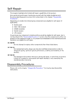
components than those listed above. NOTE: NOTE: For replacement parts, always use only Acer certified components in order to safeguard quality, optimum system performance, stability and reliability of the chapter "Disassembly Procedures" for step by step disassembly instructions. Self-Repair 1-1 - Acer TravelMate P414-41 | Lifecycle Extension Guide - Page 4
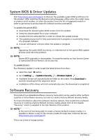
"Recovery" which is available in the User Manual of the product. NOTE: NOTE: In the event of not being able to create a Factory Default recovery media, it is possible to obtain a copy of the recovery media through Acer Customer Service (http://www.acer.com/support) This is not a free of charge - Acer TravelMate P414-41 | Lifecycle Extension Guide - Page 5
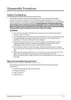
will be voided. Before you start any of the procedures in this chapter, make sure to read the following safety guidelines and the respective instructions within the chapter. CAUTION! Turn off your computer and disconnect all power sources before opening the computer cover or panels. To avoid - Acer TravelMate P414-41 | Lifecycle Extension Guide - Page 6
WEEE Annex VII Component 0 These components are classified as requiring selective treatment: Battery Memory RTC battery WLAN module SSD module Card Reader board Touchpad module I/O board Mainboard LCD panel 1-4 Disassembly Procedures - Acer TravelMate P414-41 | Lifecycle Extension Guide - Page 7
Pre-disassembly Instructions 0 Do the following prior to starting any maintenance procedures: 1. Place the system on a stable work surface. 2. Remove the AC adapter from any of the ports (A) - Acer TravelMate P414-41 | Lifecycle Extension Guide - Page 8
4. Remove the SD card from the SD card slot (C) (Figure 1-3) or (Figure 1-4). 5. Remove the smart card from the smart card slot (D) (Figure 1-4) (convertible model only). C Figure 1-3. SD Card Removal (Clamshell Model) D C Figure 1-4. SD Card and Smart Card Removal (Convertible Model) 1-6 - Acer TravelMate P414-41 | Lifecycle Extension Guide - Page 9
6. Remove the stylus pen from the stylus pen slot (E) (Figure 1-5) (convertible model only). E Figure 1-5. Stylus Pen Removal (Convertible Model) NOTE: NOTE: Make sure the system is completely powered off. Disassembly Procedures 1-7 - Acer TravelMate P414-41 | Lifecycle Extension Guide - Page 10
Base Cover Removal 0 1. Remove twelve (12) screws from the base cover (Figure 1-6). Figure 1-6. Base Cover Removal 2. Carefully pry up the base cover starting from the upper side closer to the hinge caps to release the latches. Then continue releasing the remaining latches on the left and right - Acer TravelMate P414-41 | Lifecycle Extension Guide - Page 11
3. Continue releasing the remaining latches on the left, right, and bottom sides (Figure 1-8). Figure 1-8. Base Cover Removal 4. Grasp and remove the base cover from the system (Figure 1-9). Figure 1-9. Base Cover Removal Disassembly Procedures 1-9 - Acer TravelMate P414-41 | Lifecycle Extension Guide - Page 12
Battery Pack Removal 0 Prerequisite: Base Cover Removal 1. Find the battery pack (A) in the system (Figure 1-10). 2. Detach the acetate tape (B) and the insulator mylar from the battery cable and connector (Figure 1-10). C B A Figure 1-10. Battery Pack Removal 3. Disconnect the battery cable - Acer TravelMate P414-41 | Lifecycle Extension Guide - Page 13
4. Remove the battery pack from the system (Figure 1-12). WEEE Annex VII Component: Battery Figure 1-12. Battery Pack Removal + IMPORTANT: Follow local regulations for battery disposal. Disassembly Procedures 1-11 - Acer TravelMate P414-41 | Lifecycle Extension Guide - Page 14
DIMM (Dual In-line Memory Module) Removal 0 Prerequisite: Battery Pack Removal 1. Find the DIMM module (A) in the system (Figure 1-13). 2. Push the DIMM module clips (B) outwards (Figure 1-13). B B A Figure 1-13. DIMM Module Removal 3. Remove the DIMM module from the mainboard connector (C) ( - Acer TravelMate P414-41 | Lifecycle Extension Guide - Page 15
4. Repeat steps 2 to 3 to remove another DIMM module (if applicable). Disassembly Procedures 1-13 - Acer TravelMate P414-41 | Lifecycle Extension Guide - Page 16
RTC Battery Removal 0 Prerequisite: Battery Pack Removal 1. Disconnect the RTC battery cable from the mainboard connector (A) (Figure 1-15). 2. Pry to detach the adhesive tape underneath the RTC battery (Figure 1-15). 3. Remove the RTC battery from the top assembly (Figure 1-15). WEEE Annex VII - Acer TravelMate P414-41 | Lifecycle Extension Guide - Page 17
WLAN Module Removal 0 Prerequisite: Battery Pack Removal 1. Find the WLAN module (A) on the top assembly (Figure 1-16). A Figure 1-16. WLAN Module Location 2. Disconnect the WLAN antennas cables from the WLAN module connectors (B) (Figure 1-17). 3. Remove one (1) screw securing the WLAN module in - Acer TravelMate P414-41 | Lifecycle Extension Guide - Page 18
4. Remove the WLAN module from the mainboard connector (C) (Figure 1-18). C WEEE Annex VII Component: WLAN Module Figure 1-18. WLAN Module Removal 1-16 Disassembly Procedures - Acer TravelMate P414-41 | Lifecycle Extension Guide - Page 19
SSD 2 Module Removal (Convertible Model Only) 0 Prerequisite: Battery Pack Removal 1. Remove one (1) screw securing the SSD module in place (Figure 1-19). Figure 1-19. SSD Module Removal 2. Disconnect the SSD module from the mainboard connector (A) and remove from the top assembly (Figure 1-20). - Acer TravelMate P414-41 | Lifecycle Extension Guide - Page 20
SSD 1 Module Removal 0 Prerequisite: Battery Pack Removal 1. Remove one (1) screw securing the SSD module in place (Figure 1-21). Figure 1-21. SSD Module Removal 2. Disconnect the SSD module from the mainboard connector (A) and remove from the top assembly (Figure 1-22). WEEE Annex VII Component: - Acer TravelMate P414-41 | Lifecycle Extension Guide - Page 21
LCD Module Removal (Clamshell Model) 0 Prerequisite: Battery Pack Removal 1. Disconnect the eDP cable from the mainboard connector (A) and unroute from the top assembly (Figure 1-23). A Figure 1-23. LCD Module Removal 2. Remove four (4) screws securing the LCD hinges in place (Figure 1-24). Figure - Acer TravelMate P414-41 | Lifecycle Extension Guide - Page 22
3. Lift the top assembly until it is fully open (Figure 1-25). Figure 1-25. LCD Module Removal 4. Close the top assembly and lift both LCD hinges until they are fully extended (Figure 1-26). Figure 1-26. LCD Module Removal 1-20 Disassembly Procedures - Acer TravelMate P414-41 | Lifecycle Extension Guide - Page 23
5. Open the top assembly again and lift to remove the top assembly (Figure 1-27). Figure 1-27. LCD Module Removal ! CAUTION: Make sure all cables and antennas are moved away from the device to avoid damage during removal. Disassembly Procedures 1-21 - Acer TravelMate P414-41 | Lifecycle Extension Guide - Page 24
LCD Module Removal (Convertible Model) 0 Prerequisite: SSD 2 Module Removal (Convertible Model Only) 1. Disconnect the light sensor cable from the mainboard connector (A) and detach it from the top assembly (Figure 1-28). A Figure 1-28. LCD Module Removal 2. Disconnect the eDP cable from the - Acer TravelMate P414-41 | Lifecycle Extension Guide - Page 25
3. Remove four (4) screws securing the LCD hinges in place (Figure 1-30). Figure 1-30. LCD Module Removal 4. Lift the top assembly until it is fully open (Figure 1-31). Figure 1-31. LCD Module Removal Disassembly Procedures 1-23 - Acer TravelMate P414-41 | Lifecycle Extension Guide - Page 26
5. Close the top assembly and lift both LCD hinges until they are fully extended (Figure 1-32). Figure 1-32. LCD Module Removal 6. Open the top assembly again and lift to remove the top assembly (Figure 1-33). Figure 1-33. LCD Module Removal ! CAUTION: Make sure all cables and antennas are moved - Acer TravelMate P414-41 | Lifecycle Extension Guide - Page 27
Removal (Convertible Model) 1. Remove one (1) screw securing the right USB support bracket in place (Figure 1-34). Figure 1-34. USB Board Removal 2. Release the USB support bracket from the guide pin (A) and guide tab (B) (Figure 1-35). A Figure 1-35. USB Board Removal Disassembly Procedures - Acer TravelMate P414-41 | Lifecycle Extension Guide - Page 28
securing the USB board in place (Figure 1-36). D E C Figure 1-36. USB Board Removal 7. Lift and slide to release the USB board from the guide pin (F) and I/O ports (marked with a green line). Remove the USB board from the top assembly (Figure 1-37). WEEE Annex VII Component: USB Board F Figure - Acer TravelMate P414-41 | Lifecycle Extension Guide - Page 29
Card Reader Board Removal (Clamshell Model) 0 Prerequisite: SSD 1 Module Removal 1. Remove the card reader board rubber (A) (Figure 1-38). A Figure 1-38. Card Reader Board Removal Disassembly Procedures 1-27 - Acer TravelMate P414-41 | Lifecycle Extension Guide - Page 30
2. Disconnect the card reader board FFC (B) from both, the card reader board and the mainboard connector. Then detach the middle portion of the card reader board FFC from the top assembly and remove (Figure 1-39). 3. Remove two (2) screws securing the card reader board in place (Figure 1-39). B - Acer TravelMate P414-41 | Lifecycle Extension Guide - Page 31
4. Release the card reader board from the guide pins (C) and remove from the top assembly (Figure 1-40). WEEE Annex VII Component: Card Reader Board C C Figure 1-40. Card Reader Board Removal Disassembly Procedures 1-29 - Acer TravelMate P414-41 | Lifecycle Extension Guide - Page 32
Card Reader Board Removal (Convertible Model) 0 Prerequisite: SSD 1 Module Removal 1. Remove the card reader board rubber (A) (Figure 1-41). A Figure 1-41. Card Reader Board Removal 1-30 Disassembly Procedures - Acer TravelMate P414-41 | Lifecycle Extension Guide - Page 33
2. Disconnect the card reader board FFC (B) from both, the card reader board and the mainboard connector. Then detach the middle portion of the card reader board FFC from the top assembly and remove (Figure 1-42). 3. Disconnect the card reader FFC from the card reader board connector (C) (Figure 1- - Acer TravelMate P414-41 | Lifecycle Extension Guide - Page 34
5. Release the card reader board from the guide pins (D). Then slide to release the card reader slot from the top assembly and remove the card reader board (Figure 1-43). WEEE Annex VII Component: Card Reader Board D D Figure 1-43. Card Reader Board Removal 1-32 Disassembly Procedures - Acer TravelMate P414-41 | Lifecycle Extension Guide - Page 35
Touchpad Module Removal 0 Prerequisite: SSD 1 Module Removal 1. Disconnect the card reader FFC from the card reader board connector (A) (Figure 1-44). 2. Detach the kapton tape (B) from the touchpad FFC connector (Figure 1-44). B A Figure 1-44. Touchpad Module Removal Disassembly Procedures 1-33 - Acer TravelMate P414-41 | Lifecycle Extension Guide - Page 36
3. Disconnect the touchpad FFC (C) from the touchpad connector and the mainboard connector. Then detach the middle portion of the touchpad FFC and remove it from the top assembly (Figure 1-45). 4. Disconnect the NFC module FFC (D) from the NFC module connector and the mainboard connector. Then - Acer TravelMate P414-41 | Lifecycle Extension Guide - Page 37
the top assembly and three (3) screws securing the touchpad module to the top assembly (Figure 1-47). Figure 1-47. Touchpad Module Removal 9. Remove two (2) touchpad support brackets (I) from the top assembly (Figure 1-48). I I Figure 1-48. Touchpad Module Removal Disassembly Procedures 1-35 - Acer TravelMate P414-41 | Lifecycle Extension Guide - Page 38
10. With one hand is placed underneath the touchpad module (L), release the touchpad module from the top assembly and then remove (Figure 1-49). L WEEE Annex VII Component: Touchpad Module Figure 1-49. Touchpad Module Removal 1-36 Disassembly Procedures - Acer TravelMate P414-41 | Lifecycle Extension Guide - Page 39
SSD 1 module have been disassembled prior removing the mainboard. 1. Remove the kapton tape (A) from the keyboard backlight FFC (Figure 1-50). 2. Remove one (1) screw from the support bracket (Figure 1-50). A Figure 1-50. Mainboard Removal Disassembly Procedures 1-37 - Acer TravelMate P414-41 | Lifecycle Extension Guide - Page 40
3. Release the support bracket from the guide pin (B) and guide tab (C). Then remove the support bracket from the top assembly (Figure 1-51). B C Figure 1-51. Mainboard Removal 1-38 Disassembly Procedures - Acer TravelMate P414-41 | Lifecycle Extension Guide - Page 41
4. Disconnect the USB board FFC from the mainboard connector (D) (Figure 1-52). 5. Disconnect the touchpad FFC from the mainboard connector (E) (Figure 1-52). 6. Disconnect the keyboard FPC from the mainboard connector (F) (Figure 1-52). 7. Disconnect the NFC module FFC from the mainboard connector - Acer TravelMate P414-41 | Lifecycle Extension Guide - Page 42
13. Remove four (4) screws securing the mainboard in place (Figure 1-53). Figure 1-53. Mainboard Removal 14. Release the mainboard from the guide pins (M) and its I/O ports from the I/O slots on the top assembly. Then carefully flip the mainboard t access the USB board FFC (Figure 1-54). M M Figure - Acer TravelMate P414-41 | Lifecycle Extension Guide - Page 43
15. Detach the acetate tape (N) from the USB board FFC cable connector (Figure 1-55). N Figure 1-55. Mainboard Removal 16. Disconnect the USB board FFC from the mainboard connector (O) (Figure 1-56). WEEE Annex VII Component: Mainboard O Figure 1-56. Mainboard Removal Disassembly Procedures 1-41 - Acer TravelMate P414-41 | Lifecycle Extension Guide - Page 44
! CAUTION: USB board FFC (Flexible Flat Circuit), touchpad FFC, and keyboard FPC (Flexible Printed Circuit) can be damaged if removed while the mainboard connectors are locked. Figure 1-57. Mainboard + IMPORTANT: Circuit board >10 cm² has been highlighted with a yellow rectangle as shown in Figure - Acer TravelMate P414-41 | Lifecycle Extension Guide - Page 45
LCD Bezel Removal (Clamshell Model Only) 0 Prerequisite: LCD Module Removal (Clamshell Model) 1. Push down both hinges (Figure 1-58). Figure 1-58. LCD Bezel Removal 2. Pry the LCD bezel from the bottom side to release the latches (Figure 1-59). Figure 1-59. LCD Bezel Removal Disassembly Procedures - Acer TravelMate P414-41 | Lifecycle Extension Guide - Page 46
3. Pry the LCD bezel from the right side to release latches (Figure 1-60). Figure 1-60. LCD Bezel Removal 4. Pry the LCD bezel from the left side to release latches (Figure 1-61). Figure 1-61. LCD Bezel Removal 1-44 Disassembly Procedures - Acer TravelMate P414-41 | Lifecycle Extension Guide - Page 47
5. Continue along the upper side of the bezel until all the latches have been released (Figure 1-62). Then lift and remove the bezel from LCD module. Figure 1-62. LCD Bezel Removal Disassembly Procedures 1-45 - Acer TravelMate P414-41 | Lifecycle Extension Guide - Page 48
LCD Panel Removal (Clamshell Module) 0 Prerequisite: LCD Bezel Removal (Clamshell Model Only) NOTE: NOTE: The eCD cable includes LCD panel cable and camera cable. 6. Unroute the eDP cable from the bottom routing channel and LCD hinge cap (Figure 1-63). Figure 1-63. LCD Panel Removal 1-46 - Acer TravelMate P414-41 | Lifecycle Extension Guide - Page 49
7. Pry slightly to access the double-sided mounting tape (A) underneath the LCD panel (B). Then pull to detach the double-sided mounting tape from the LCD cover. Repeat the same procedure to remove the double-sided mounting tape on another side of the LCD panel (Figure 1-64). WEEE Annex VII - Acer TravelMate P414-41 | Lifecycle Extension Guide - Page 50
9. Lift the latch securing the eDP cable (Figure 1-66). Figure 1-66. LCD Panel Removal 10. Disconnect the eDP cable from the LCD panel connector (D) (Figure 1-67). D Figure 1-67. LCD Panel Removal 11. Remove the LCD panel from the LCD cover. 1-48 Disassembly Procedures - Acer TravelMate P414-41 | Lifecycle Extension Guide - Page 51
LCD Panel Removal (Convertible Model) 0 Prerequisite: LCD Module Removal (Convertible Model) NOTE: NOTE: The eDP cable includes LCD panel cable, touch sensor cable, and camera cable. 1. Starting near the camera module, pry the upper side LCD cover latches (Figure 1-68). Figure 1-68. LCD Panel - Acer TravelMate P414-41 | Lifecycle Extension Guide - Page 52
2. Continue releasing the right and left side latches (Figure 1-69). Figure 1-69. LCD Panel Removal 3. Release the bottom side latches (Figure 1-70). 4. Release the eDP cable (A) from the LCD hinge cap. Then remove the LCD panel from the LCD cover (Figure 1-70). WEEE Annex VII Component: LCD Panel - Acer TravelMate P414-41 | Lifecycle Extension Guide - Page 53
not be disassembled. In the event that the keyboard can no longer be used, replace the entire top assembly. Figure 1-71. Top Assembly Disassembly Procedures 1-51 - Acer TravelMate P414-41 | Lifecycle Extension Guide - Page 54
Electronic Boards Diagrams Figure 1-72. System Block Diagram 1-52 Electronic Boards Diagrams - Acer TravelMate P414-41 | Lifecycle Extension Guide - Page 55
attempt to open the computer yourself; contact your dealer or authorized service center for assistance. Troubleshooting tips 0 This computer incorporates an advanced design that delivers on-screen error message reports to help you solve problems. If the system reports an error message or an error - Acer TravelMate P414-41 | Lifecycle Extension Guide - Page 56
FRU (Field Replaceable Unit) List Please contact your local service center to find out how to obtain the part or replace your device. 1-54 FRU (Field Replaceable Unit) List - Acer TravelMate P414-41 | Lifecycle Extension Guide - Page 57
Exploded Diagrams 1 2 3 4 9 10 12 13 14 15 16 17 21 23 24 Figure 1-73. System Exploded Diagram Table 1-2. System Exploded Diagram No. Description 1 Top assembly 2 Fingerprint board FFC 3 Fingerprint board 4 Fingerprint board bracket 5 Touchpad 6 Touchpad bracket 7 Conductive fabric with - Acer TravelMate P414-41 | Lifecycle Extension Guide - Page 58
Table 1-2. System Exploded Diagram No. Description 10 Rear speaker 11 Left speaker 12 I/O board 13 I/O board FFC 14 Left I/O board bracket 15 Acer Active Stylus Pen 16 Stylus holder 17 Stylus charger cable 18 Mainboard 19 Card reader board 20 Right I/O board bracket 21 Fan 22 Heatsink - Acer TravelMate P414-41 | Lifecycle Extension Guide - Page 59
1 2 4 3 5 6 7 Figure 1-74. LCD Assembly Exploded Diagram (Clamshell Model) Table 1-3. LCD Assembly Exploded Diagram No. Description 1 LCD bezel 2 LCD panel 3 LCD cable for HD 4 Rubbers for microphone modules 5 Camera 6 Hinges 7 LCD cover FRU (Field Replaceable Unit) List 1-57 - Acer TravelMate P414-41 | Lifecycle Extension Guide - Page 60
1 2 3 6 4 5 7 8 Figure 1-75. LCD Assembly Exploded Diagram (Convertible Model) Table 1-4. LCD Assembly Exploded Diagram No. Description 1 LCD module 2 Camera 3 Rubbers for microphone modules 4 Ambient light board 5 G-sensor board 6 Ambient light board and G-sensor board cable 7 LCD cover - Acer TravelMate P414-41 | Lifecycle Extension Guide - Page 61
Software Update Updating your software 0 Please visit http://go.acer.com/?id=17883 Software Update 1-59 - Acer TravelMate P414-41 | Lifecycle Extension Guide - Page 62
hold down the Shift key while you select the Power icon > Restart in the lower-right corner of the screen. After your computer restarts, select Troubleshoot > Reset this PC. Option 3: Select Start , then press and hold down the Shift key while you select the Power icon > Restart to restart your
-
 1
1 -
 2
2 -
 3
3 -
 4
4 -
 5
5 -
 6
6 -
 7
7 -
8
-
9
-
10
-
11
-
12
-
13
-
14
-
15
-
16
-
17
-
18
-
19
-
20
-
21
-
22
-
23
-
24
-
25
-
26
-
27
-
28
-
29
-
30
-
31
-
32
-
33
-
34
-
35
-
36
-
37
-
38
-
39
-
40
-
41
-
42
-
43
-
44
-
45
-
46
-
47
-
48
-
49
-
50
-
51
-
52
-
53
-
54
-
55
-
56
-
57
-
58
-
59
-
60
-
61
-
62
 |
 |

TravelMate P414-41
TravelMate Spin P414RN-41
LIFECYCLE EXTENSION
GUIDE