Acer TravelMate Spin B311RA-31 Lifecycle Extension Guide
Acer TravelMate Spin B311RA-31 Manual
 |
View all Acer TravelMate Spin B311RA-31 manuals
Add to My Manuals
Save this manual to your list of manuals |
Acer TravelMate Spin B311RA-31 manual content summary:
- Acer TravelMate Spin B311RA-31 | Lifecycle Extension Guide - Page 1
TravelMate B3 / TM311R-31 / TM311RN-31 / TMB311-31 / TMB311R-31 / TMB311RN-31 / TravelMate B311-31 / TravelMate B311R-31 / TravelMate B311RN-31 Lifecycle Extension Guide 1 - Acer TravelMate Spin B311RA-31 | Lifecycle Extension Guide - Page 2
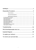
5 Pre-disassembly Instructions 6 Removing the Lower case 7 Removing the Battery 9 Removing the SSD 11 Removing the WLAN module 12 Removing the USB board 14 Removing the RJ45 board 15 Removing the MB 16 Removing the Touchpad module 19 Removing the LCD panel 21 Troubleshooting 26 FRU (Field - Acer TravelMate Spin B311RA-31 | Lifecycle Extension Guide - Page 3
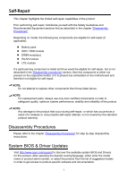
warranty. Disassembly Procedures Please refer to the chapter "Disassembly Procedures" for step by step disassembly instructions. System BIOS & Driver Updates Visit http://www.acer.com/support to discover the available system BIOS and Drivers for this product. After selecting the desired country - Acer TravelMate Spin B311RA-31 | Lifecycle Extension Guide - Page 4
BIOS upgrades or downgrades, if not performed by an Acer Service Center or authorized Service Partner, are at own risk. To update Drivers: Run Windows media, please refer to the chapter "Recovery" which is available in the User Manual of the product. NOTE: In the event of not being able to create a - Acer TravelMate Spin B311RA-31 | Lifecycle Extension Guide - Page 5
will be voided. Before you start any of the procedures in this chapter, make sure to read the following safety guidelines and the respective instructions within the chapter. CAUTION! Turn off your computer and disconnect all power sources before opening the computer cover or panels. To avoid - Acer TravelMate Spin B311RA-31 | Lifecycle Extension Guide - Page 6
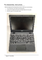
Pre-disassembly Instructions Before proceeding with the disassembly procedure, make sure to do the following: 1. Turn off the power to the system and all peripherals. 2. Unplug the AC - Acer TravelMate Spin B311RA-31 | Lifecycle Extension Guide - Page 7
Removing the Lower case 1. Place the laptop on flat while lower case should be upwards. Use screwdriver to remove 10 screw of lower case. The spec of NO 1 to NO 2 is SCREW_M2.5*6.7 mm_0.8 mm_4 mm_BLACK, the spec of NO 3 to NO 13 is SCREW_M2*5 mm_0.8 mm_4 mm_BLACK. Figure 3-3. Lower case Table 3-2. - Acer TravelMate Spin B311RA-31 | Lifecycle Extension Guide - Page 8
2. Open the buckle with a pick as showed figure3-4, then remove the lower case from the bottom side as shown in picture. Figure 3-4. Lower case Figure 3-5. Lower case - Acer TravelMate Spin B311RA-31 | Lifecycle Extension Guide - Page 9
Removing the Battery 1. Remove 2 screws from upper case. Figure 3-6. Battery Table 3-3. Battery Screw Step Screw Remove battery SCREW_M2*4 mm_0.6 mm_5 mm_silver Quantity 2 Screw Type 2. Remove the acetate cloth from the battery. Torque/kgfcm 1.8+/-0.1 kgf.cm Figure 3-7. Battery - Acer TravelMate Spin B311RA-31 | Lifecycle Extension Guide - Page 10
3. Disconnect the battery cable from the MB as shown in picture. Figure 3-8. Battery 4. Remove the battery from the MB as shown in picture. Battery : WEEE Annex VII component Figure 3-9. Battery - Acer TravelMate Spin B311RA-31 | Lifecycle Extension Guide - Page 11
Removing the SSD 1. Remove 1 screw from SSD. Figure 3-10. SSD Table 3-4. SSD Screw Step Remove SSD Screw SCREW_M2*3mm_0.65 mm_5mm_BLACK_BLA CK Quantity 1 2. Remove SSD from MB. Screw Type Torque/kgfcm 1.5+/-0.1 kgf.cm SSD : WEEE Annex VII component Figure 3-11. SSD - Acer TravelMate Spin B311RA-31 | Lifecycle Extension Guide - Page 12
Removing the WLAN module 1. Remove the acetate cloth on the WLAN cable. Figure 3-12. WLAN module 2. Disconnect the WLAN cable connectors on the WLAN module. Please notice the color and position. Figure 3-12. WLAN module - Acer TravelMate Spin B311RA-31 | Lifecycle Extension Guide - Page 13
3. Remove 1 screw on the WLAN module. Figure 3-13. WLAN module Table 3-5. WLAN Screw Step Screw Remove WLAN SCREW_M2*3 mm_0.65 mm_5 mm_BLACK Quantity 1 Screw Type 4. Remove the WLAN module from the MB. Torque/kgfcm 1.5+/-0.1 kgf.cm WLAN : WEEE Annex VII component Figure 3-14. WLAN module - Acer TravelMate Spin B311RA-31 | Lifecycle Extension Guide - Page 14
Removing the USB board 1. Remove 2 screws on the IO board. Figure 3-19. USB board Table 3-7. USB board screw Step Screw Quantity Screw Type Torque/kgfcm Remove USB board SCREW_M2*3 mm_0.65 mm_5 mm_BLACK 1 2. Remove the IO FFC from the USB board. 1.5+/-0.1 kgf.cm UB : WEEE Annex VII - Acer TravelMate Spin B311RA-31 | Lifecycle Extension Guide - Page 15
Removing the RJ45 board 1. Remove 2 screws on the RJ45 board. 1 2 Figure 3-21. RJ45 board Table 3-8. RJ45 board screw Step Screw Remove SCREW_M2*3mm_0.6 RJ45 board 5 mm_5 mm_BLACK 2. Remove the FFC from the RJ45 board. Quantity Screw Type Torque/kgfcm 2 1.5+/-0.1 kgf.cm RJ45 Board : - Acer TravelMate Spin B311RA-31 | Lifecycle Extension Guide - Page 16
Removing the MB 1. Remove the acetate cloth from the KB FFC connector. Figure 3-29. MB 2. Disconnect the FP FFC, KB FFC, LCD cable, LVDS cable(Glass version) from the MB .( All of them are ZIF connectors) Figure 3-30. MB - Acer TravelMate Spin B311RA-31 | Lifecycle Extension Guide - Page 17
3. Turn over the battery from the uppercase. RTC : WEEE Annex VII component Figure 3-31. MB 4. Remove 6 screws on the MB. 4 2 5 6 7 3 1 Figure 3-32. MB Table 3-10. MB Screw Step Screw Quantity Screw Type Torque/kgfcm Remove MB SCREW_M2*3mm_0.65 mm_5 mm_BLACK 7 1.5+/-0.1 kgf.cm - Acer TravelMate Spin B311RA-31 | Lifecycle Extension Guide - Page 18
5. Lift the MB from the left side of the upper case. MB : WEEE Annex VII component Figure 3-33. MB - Acer TravelMate Spin B311RA-31 | Lifecycle Extension Guide - Page 19
Removing the Touchpad module 1. Disconnect the TP FFC connector on the touch pad, then remove it from the touch pad. Figure 3-34. Touch pad module 2. Remove the conductive cloth from the touchpad and upper case Figure 3-35. Touch pad module - Acer TravelMate Spin B311RA-31 | Lifecycle Extension Guide - Page 20
3. Remove 4 screws on the TP bracket. Then remove the TP bracket from the upper case. 2 3 4 1 Figure 3-36. Touch pad module Table 3-11. Touchpad Screw Step Screw Remove Touch pad SCREW_M2*3mm_0. 65 mm_5 mm_BLACK SCREW_M2.0*L3.0_T 0.65_D6.5*3.65mm_0. 65 mm_6.5 mm_silver Quantity Screw Type - Acer TravelMate Spin B311RA-31 | Lifecycle Extension Guide - Page 21
Removing the LCD panel 1. Open the bezel from the left or right as below, then remove the bezel from the LCD cover. (Bezel version) Figure 3-45. LCD bezel (Glass version) - Acer TravelMate Spin B311RA-31 | Lifecycle Extension Guide - Page 22
2. Remove the acetate cloth on the LCD cable and Camera cable(Bezel version). Figure 3-46. LCD panel 3. Pull the easy-pull-glue out of the LCD. NOTE: During the pulling, it is necessary to apply even force and smoothness, and the force is not too strong until the glue is pulled away from the LCD ( - Acer TravelMate Spin B311RA-31 | Lifecycle Extension Guide - Page 23
4. Disconnect the LCD cable from the camera module and LED module. (Bezel version) Figure 3-48. LCD panel (Glass version) 5. Pick up the LCD cable from the LCD cover groove, flip the LCD panel from the top , then remove the LCD from the LCD cover. LCD : WEEE Annex VII component Figure 3-49. - Acer TravelMate Spin B311RA-31 | Lifecycle Extension Guide - Page 24
(Bezel version) Figure 3-50. LCD panel (Glass version) - Acer TravelMate Spin B311RA-31 | Lifecycle Extension Guide - Page 25
6. Disconnect the LCD cable from the LCD. Figure 3-51. LCD panel - Acer TravelMate Spin B311RA-31 | Lifecycle Extension Guide - Page 26
Troubleshooting - Acer TravelMate Spin B311RA-31 | Lifecycle Extension Guide - Page 27
FRU (Field Replaceable Unit) List Please contact your local service center to find out how to obtain the part or replace your device. - Acer TravelMate Spin B311RA-31 | Lifecycle Extension Guide - Page 28
Exploded Diagrams Figure6-1. Exploded Diagram (180°) Table 6-1.Exploded Diagram Item 1 2 3 Description BEZEL SCREW Acer Part # 60.VMUN8.002 86.VMUN8.001 LCD CABLE 50.VMUN8.005 Item 7 8 9 4 MIC RUBBER 47.VMUN8.002 10 5 CAMERA KS.0HD06.012 11 6 LED BOARD 55.VMUN8.003 12 Description - Acer TravelMate Spin B311RA-31 | Lifecycle Extension Guide - Page 29
Figure6-2. Exploded Diagram (360°) Table 6-2.Exploded Diagram Item 1 2 Description LCD PANEL BEZEL Acer Part # 6M.VMVN8.001 60.VMUN8.002 Item 8 9 3 LCD CABLE 50.VMYN8.002 10 4 MIC RUBBER 47.VMYN8.002 11 5 CAMERA KS.0HD06.012 12 6 LED BOARD 55.VMUN8.003 13 7 CONDUCTIVE CLOTH 47. - Acer TravelMate Spin B311RA-31 | Lifecycle Extension Guide - Page 30
Figure6-3. Exploded Diagram Table 6-3.Exploded Diagram Item Description Acer Part # Item Description 1 KEYBOARD NK.I111S.09E 13 PEN 2 UPPER CASE 60.VN0N8.001 14 TOUCHPAD MODULE 3 SSD KN.1280B.010 15 4 RTC BATTERY \Included in the MB 16 UB BATTERY 5 WLAN MODULE KE.11A0N.010 - Acer TravelMate Spin B311RA-31 | Lifecycle Extension Guide - Page 31
hold down the Shift key while you select the Power icon > Restart in the lower-right corner of the screen. After your computer restarts, select Troubleshoot > Reset this PC. Option 3: Select Start , then press and hold down the Shift key while you select the Power icon > Restart to restart your
-
 1
1 -
 2
2 -
 3
3 -
 4
4 -
 5
5 -
 6
6 -
 7
7 -
8
-
9
-
10
-
11
-
12
-
13
-
14
-
15
-
16
-
17
-
18
-
19
-
20
-
21
-
22
-
23
-
24
-
25
-
26
-
27
-
28
-
29
-
30
-
31
 |
 |

1
TravelMate B3 / TM311R-31 / TM311RN-31 / TMB311-31 / TMB311R-31 /
TMB311RN-31 / TravelMate B311-31 / TravelMate B311R-31 /
TravelMate B311RN-31
Lifecycle Extension Guide