Alpine T320 User Manual
Alpine T320 - V12 MRV Amplifier Manual
 |
View all Alpine T320 manuals
Add to My Manuals
Save this manual to your list of manuals |
Alpine T320 manual content summary:
- Alpine T320 | User Manual - Page 1
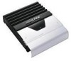
English Français Español R MRV-T420/MRV-T320 2/1 CHANNEL POWER AMPLIFIER • OWNER'S MANUAL Please read this manual to maximize your enjoyment of the outstanding performance and feature capabilities of the equipment, then retain the manual for future reference. • MODE D'EMPLOI Veuillez lire ce mode - Alpine T320 | User Manual - Page 2
MANUAL thoroughly to familiarize yourself with each control and function. We at ALPINE hope that your new MRV-T420/MRV-T320 will give you many years of listening enjoyment. In case of problems when installing so may result in fire, etc. BEFORE WIRING, DISCONNECT THE CABLE FROM THE NEGATIVE BATTERY - Alpine T320 | User Manual - Page 3
lo descrito en el manual para evitar obstá PROBLEM APPEARS. Failure to do so may cause personal injury or damage to the product. Return it to your authorized Alpine dealer or the nearest Alpine Service Center for repairing. HAVE THE WIRING AND INSTALLATION DONE BY EXPERTS. The wiring and installation - Alpine T320 | User Manual - Page 4
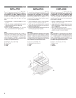
heat is produced when the amplifier is in operation. For this reason, the amplifier should be mounted in a location which will allow for free circulation of air, such as inside the trunk. For alternate installation locations, please contact your authorized Alpine dealer. En raison de la - Alpine T320 | User Manual - Page 5
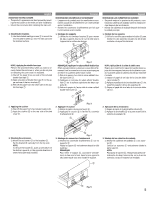
5, poussez-le verticalement du bas vers le haut, dans le sens opposé à celui dans lequel vous avez installé le support. 3. Montaje de las cubiertas de acabado 1) Montar las cubiertas de acabado 9 a los soportes 5. Colocar los soportes 5 verticalmente desde la parte superior. NOTA: Para quitar - Alpine T320 | User Manual - Page 6
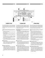
POWER SUPPLY 3 Fig. 6 CONEXIONES Before making connections, be sure to turn the power off to all audio components. Connect the yellow battery lead from the amp . Su proveedor Alpine dispone de varios supresores de ruido Alpine. Solicítele más información. • Su proveedor Alpine conoce la mejor - Alpine T320 | User Manual - Page 7
this lead, the wire gauge should be 8 AWG or larger. 5 MRV-T420 ... 50A amp fuse (or two 25A fuses in parallel) MRV-T320 ... 30A amp fuse 5 Remote Turn should connect these wires to the speaker output leads of your head unit. The MRV-T320 accepts input from high power or standard power head units. 8 - Alpine T320 | User Manual - Page 8
produit/Extremo del producto Fig. 7 Lead/Conducteur/Alambre Lead Terminal/Borne de conducteur/Terminal Español Fig. 8 Cautions on wire lead connections When using third-party wire cables (power supply cord), use the supplied hex screws and the hex wrench to simplify the connection. Refer to the - Alpine T320 | User Manual - Page 9
type mise à la terre) ou ne peut pas supporter (+) 12V lors de la connexion à un autre é to the 3A fuse mentioned above, may be installed in-line on the MRV-T420/MRVT320 turn-on amplifier will remain on and drain the battery. 1 Blue/White 2 Power Antenna 3 Remote Turn-On Lead 4 To other Alpine - Alpine T320 | User Manual - Page 10
English MOUNTING THE TERMINAL COVER • The product's appearance can be improved by mount- ing the terminal cover on the main unit after installation. • Mount the terminal cover after the connections have been made and you have checked that operation is normal. Français MONTER LE COUVERCLE CACHE- - Alpine T320 | User Manual - Page 11
so the sound is no longer distorted to achieve the optimum gain setting. É Crossover Mode Selector Switch (LP) a) Set to the "LP" position when the amplifier is used to drive a subwoofer. The frequen- OFF LP cies above the crossover point will be at- tenuated at 12 dB/octave. b) Set to the - Alpine T320 | User Manual - Page 12
puede ser confirmado con el indicador. • Protection indicator (PROTECTION) Blue Light Red Light Condition Amplifier circuit is normal. Amplifier circuit is abnormal. Solution Contact your authorized Alpine dealer. • Indicateur de protection (PROTECTION) Bleu Rouge Etat Allumé Le circuit de - Alpine T320 | User Manual - Page 13
SYSTEM DIAGRAMS/DIAGEnRglAishMMES DU SYSTEME/DIAGRAFrMançAaiSs DEL SISTEMA MRV-T420/MRV-T320 q 2-Channel INPUT (R) CH-1 CH-2 BRIDGED CH-2 CH-1 SPEAKER OUTPUT BATTERY REMOTE GND 25A 25A 25 25 FUSE POWER SUPPLY 5 â É OFF LP Ü OFF * HP * When using as subsonic filter, set to HP - Alpine T320 | User Manual - Page 14
â OFF HP (MRV-T420) MRV-T320 (L) INPUT (R) CH-1 CH-2 BRIDGED CH-2 CH-1 BATTERY REMOTE GND 25A 25A 25 25 SPEAKER OUTPUT ã - + FUSE POWER SUPPLY 5 q Speaker Input Leads System/Système des conducteurs d'entrée de haut-parleur/Sistema de los conductores de entrada del altavoz CH-1 CH - Alpine T320 | User Manual - Page 15
50Wx2 Per channel into 2 ohms (0.3% THD) .. MRV-T420: 120Wx2 MRV-T320: 80Wx2 Bridged into 4 ohms (0.3% THD) ........ MRV-T420: 240Wx1 MRV-T320: 160Wx1 Power Output: RMS Continuous Power (at 14.4V, 20 Hz to 20 kHz) Per channel into 4 ohms (0.08% THD) MRV-T420: 110Wx2 MRV-T320: 80Wx2 Per channel into - Alpine T320 | User Manual - Page 16
SERVICE CARE Français SOINS PRATIQUES Español CUIDADOS PRACTICOS IMPORTANT NOTICE This Amplifier installed and used properly in accordance with the manufacturer's instructions Insulation Tube (for Power Supply 1 • • Couvercle cache-bornes 1 • Support 2 • Clé hexagonale (M3 1 ALPINE ELECTRONICS,
-
 1
1 -
 2
2 -
 3
3 -
 4
4 -
 5
5 -
 6
6 -
 7
7 -
8
-
9
-
10
-
11
-
12
-
13
-
14
-
15
-
16
 |
 |

R
• OWNER'S MANUAL
Please read this manual to maximize your enjoyment of the outstanding
performance and feature capabilities of the equipment, then retain the
manual for future reference.
• MODE D'EMPLOI
Veuillez lire ce mode d'emploi pour tirer pleinement profit des
excellentes performances et fonctions de cet appareil, et conservez-le
pour toute référence future.
• MANUAL DE OPERACION
Lea este manual, por favor, para disfrutar al máximo de las
excepcionales prestaciones y posibilidades funcionales que ofrece el
equipo, luego guarde el manual para usarlo como referencia en el futuro.
MRV-T420/MRV-T320
2/1 CHANNEL POWER AMPLIFIER
CONTENTS
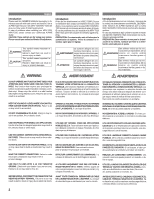
WARNING
..................................................................
2
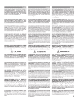
CAUTION
...................................................................
3
INSTALLATION
..........................................................
4
CONNECTIONS
..........................................................
6
CONNECTIONS CHECK LIST
......................................
9
SWITCH SETTINGS
.................................................
11
SYSTEM DIAGRAMS
...............................................
13
SPECIFICATIONS
.....................................................
15
TABLE DES MATIERES
AVERTISSEMENT
......................................................
2
ATTENTION
................................................................
3
INSTALLATION
..........................................................
4
CONNEXIONS
............................................................
6
LISTE DE VERIFICATION DES CONNEXIONS
.............
9
REGLAGES DE COMMUTATEUR
..............................
11
DIAGRAMMES DU SYSTEME
..................................
13
SPECIFICATIONS
.....................................................
15
INDICE
ADVERTENCIA
...........................................................
2
PRUDENCIA
..............................................................
3
INSTALACION
............................................................
4
CONEXIONES
............................................................
6
LISTA DE VERIFICACION DE CONEXIONES
...............
9
AJUSTES DEL INTERRUPTOR
.................................
11
DIAGRAMAS DEL SISTEMA
....................................
13
ESPECIFICACIONES
................................................
15
Español
Français
English