Amana AMV2307PFS Installation Instructions
Amana AMV2307PFS Manual
 |
View all Amana AMV2307PFS manuals
Add to My Manuals
Save this manual to your list of manuals |
Amana AMV2307PFS manual content summary:
- Amana AMV2307PFS | Installation Instructions - Page 1
illustration in these installation instructions. Table of Contents MICROWAVE HOOD COMBINATION SAFETY 1 INSTALLATION REQUIREMENTS 2 Tools and Parts 2 Remove Cardboard Template 2 Location Requirements 2 Product Dimensions 3 Electrical Requirements 3 INSTALLATION INSTRUCTIONS 4 Remove Mounting - Amana AMV2307PFS | Installation Instructions - Page 2
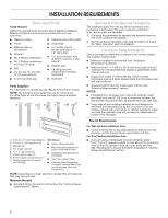
or roof venting) Not Shown: ■■ Upper cabinet template ■■ Mounting plate (attached to back of microwave oven) ■■ Cardboard template (part of packaging) ■■ Aluminum grease filters ■■ Charcoal filters (Depending on model, charcoal filters may not be included. See User Instructions.) NOTE: Depending - Amana AMV2307PFS | Installation Instructions - Page 3
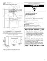
an adapter. Do not use an extension cord. Failure to follow these instructions can result in death, fire, or electrical shock. Observe all governing microwave oven. A. 2" x 4" wall stud B. Grounded 3 prong outlet *30" (76.2 cm) is typical for 66" (167.6 cm) installation height. Exact dimensions - Amana AMV2307PFS | Installation Instructions - Page 4
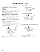
: Skip this section if you are using recirculation installation. Keep the damper assembly in case the venting method is changed, or the microwave oven is reinstalled in another location where wall or roof venting may be used. Wall Venting Installation Only 1. Remove screws attaching damper plate to - Amana AMV2307PFS | Installation Instructions - Page 5
Step 1 from "Wall Venting Installation Only." 2. Repeat Step 2 from "Wall Venting Installation Only." 3. Repeat Step 3 from "Wall Venting Installation Only." 4. Repeat Step 4 from "Wall Venting Installation Only." 5. Rotate blower motor so that exhaust ports face the top of microwave oven, and flat - Amana AMV2307PFS | Installation Instructions - Page 6
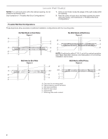
exist within the cabinet opening, do not install the microwave oven. See illustrations in "Possible Wall Stud cm) of the vertical centerline (see "Mark Rear Wall" section), only recirculation or roof venting installation can be done. Wall Stud at End Hole Figure 3 Wall Studs at End Holes Figure - Amana AMV2307PFS | Installation Instructions - Page 7
microwave oven must be installed the mounting plate aside. Wall Venting Installation Only Upper cabinet bottom ³⁄₈" unusable, measure and mark the wall with the dimensions described in Step 4. D A C B A. cm) from the centerline. 5. With the support tabs facing forward (see illustrations in "Locate - Amana AMV2307PFS | Installation Instructions - Page 8
1 wall stud as well as at both ends. 1. With the support tabs of the mounting plate facing forward, insert 3/16-24 x guides. ■■ If the wall behind the microwave oven (as installed) has a partial wall covering (for example, tile backsplash), be sure the "Rear Wall" arrows align to the thickest part - Amana AMV2307PFS | Installation Instructions - Page 9
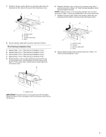
1/4-20 x 3" bolts and washers used to secure the microwave oven to the upper cabinet. For Roof Venting Installation Only 7. Cut C\v" (19 mm) hole at one sheet metal screws. A B A. Mounting plate B. Support tabs 4. With front of microwave oven still tilted, thread power supply cord through the - Amana AMV2307PFS | Installation Instructions - Page 10
cabinet bottom and the microwave oven. A 2. Connect vent to damper assembly. A B A. Vent B. Damper assembly (under vent) Complete Installation 1. Install filters. Refer to the User Instructions for filter placement. WARNING A. Bolts For Roof Venting Installation Only 1. Insert damper assembly - Amana AMV2307PFS | Installation Instructions - Page 11
only. NOTES: ■■ Vent materials needed for installation are not provided with microwave hood combination. ■■ We do not recommend using a flexible metal vent. ■■ To avoid possible product damage, be sure to vent air outside, unless using recirculation installation. Do not vent exhaust air into - Amana AMV2307PFS | Installation Instructions - Page 12
In addition, a rectangular 3" (7.6 cm) extension vent between the damper assembly and rectangular to round transition piece must be installed to keep the damper from sticking. ASSISTANCE Call your authorized dealer or service center. When you call, you will need the microwave oven model number and
-
 1
1 -
 2
2 -
 3
3 -
 4
4 -
 5
5 -
 6
6 -
 7
7 -
8
-
9
-
10
-
11
-
12
 |
 |
MICROWAVE HOOD COMBINATION
INSTALLATION INSTRUCTIONS
This product is suitable for use above electric or gas cooking products up to and including 36" (91.4 cm) wide. See “Installation
Requirements” section for further notes.
These installation instructions cover different models. The appearance of your particular model may differ slightly from the illustration
in these installation instructions.
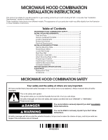
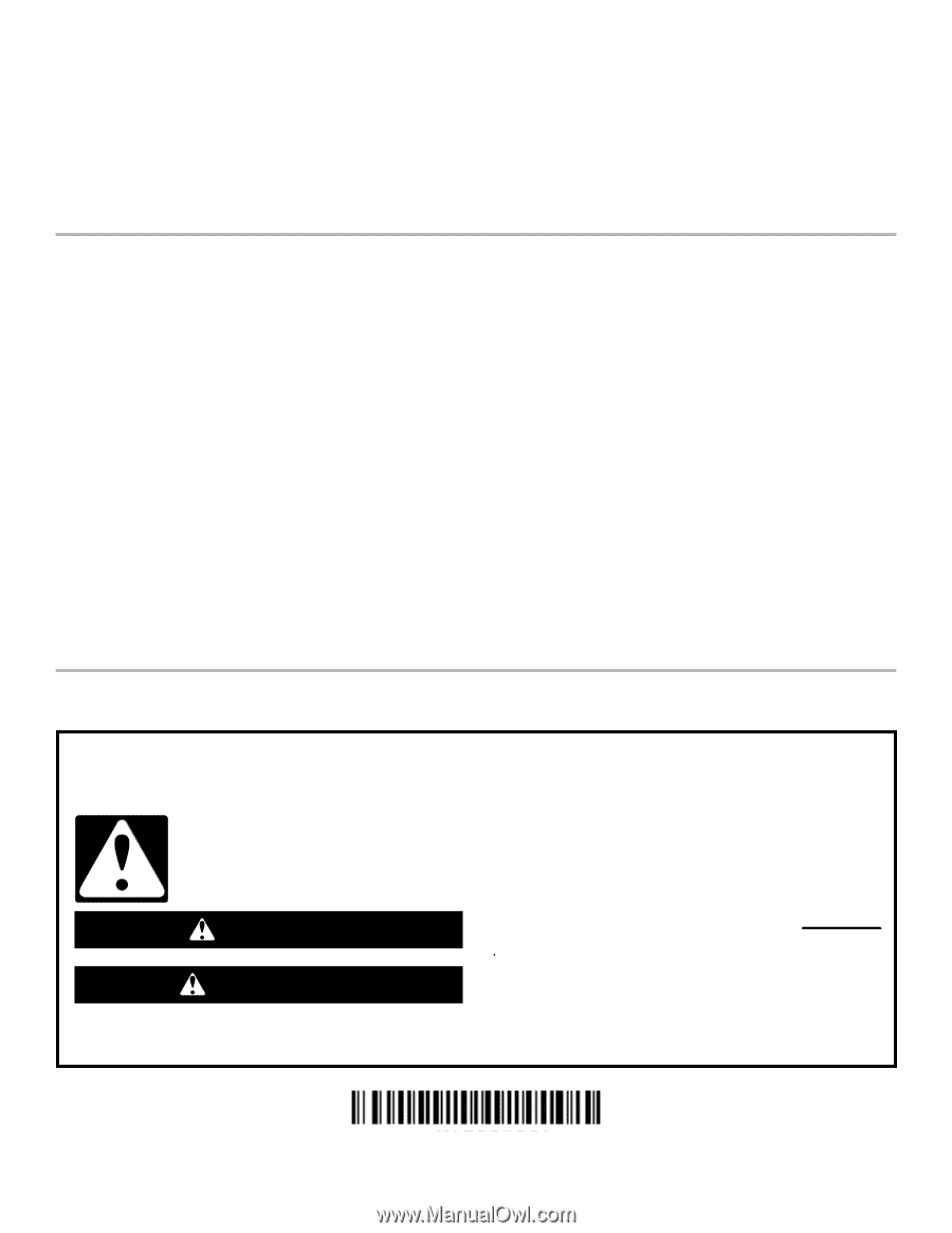
MICROWAVE HOOD COMBINATION SAFETY
You can be killed or seriously injured if you don't immediately
You
can be killed or seriously injured if you don't follow
All safety messages will tell you what the potential hazard is, tell you how to reduce the chance of injury, and tell you what can
happen if the instructions are not followed.
Your safety and the safety of others are very important.
We have provided many important safety messages in this manual and on your appliance. Always read and obey all safety
messages.
This is the safety alert symbol.
This symbol alerts you to potential hazards that can kill or hurt you and others.
All safety messages will follow the safety alert symbol and either the word “DANGER” or “WARNING.”
These words mean:
follow instructions.
instructions.
DANGER
WARNING
MICROWAVE HOOD COMBINATION SAFETY
............................
1
INSTALLATION REQUIREMENTS
.................................................
2
Tools and Parts
.............................................................................
2
Remove Cardboard Template
......................................................
2
Location Requirements
................................................................
2
Product Dimensions
.....................................................................
3
Electrical Requirements
...............................................................
3
INSTALLATION INSTRUCTIONS
...................................................
4
Remove Mounting Plate
...............................................................
4
Rotate Blower Motor
....................................................................
4
Locate Wall Stud(s)
......................................................................
6
Mark Rear Wall
.............................................................................
7
Drill Holes in Rear Wall
.................................................................
7
Attach Mounting Plate to Wall
.....................................................
8
Prepare Upper Cabinet
................................................................
8
Install Damper Assembly
.............................................................
9
Install the Microwave Oven
..........................................................
9
Complete Installation
.................................................................
10
VENTING DESIGN SPECIFICATIONS
.........................................
11
ASSISTANCE
................................................................................
12
Replacement Parts
.....................................................................
12
Accessories
................................................................................
12
Table of Contents
W10823831A