Asus A58M-E R2.0 User Guide
Asus A58M-E R2.0 Manual
 |
View all Asus A58M-E R2.0 manuals
Add to My Manuals
Save this manual to your list of manuals |
Asus A58M-E R2.0 manual content summary:
- Asus A58M-E R2.0 | User Guide - Page 1
A58M-E Motherboard - Asus A58M-E R2.0 | User Guide - Page 2
ASUS"). Product warranty or service will not be extended or missing. ASUS PROVIDES THIS MANUAL "AS IS" WITHOUT WARRANTY OF (1) for free by downloading it from http://support.asus.com/download or (2) for the cost If however you encounter any problems in obtaining the full corresponding source - Asus A58M-E R2.0 | User Guide - Page 3
guide...iv Package contents...vi A58M-E specifications summary vi Product introduction 1.1 Before you proceed 1-1 1.2 Motherboard overview 1-1 1.3 Accelerated Processing Unit (APU 1-3 1.4 System memory 1-6 1.5 Expansion slots 1-9 1.6 Jumpers...1-10 1.7 Connectors 1-11 1.8 Software support - Asus A58M-E R2.0 | User Guide - Page 4
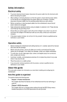
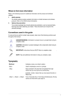
qualified service technician or your retailer. Operation safety • Before installing the motherboard and adding devices on it, carefully read all the manuals technical problems with the product, contact a qualified service technician or your retailer. About this guide This user guide contains the - Asus A58M-E R2.0 | User Guide - Page 5
dealer. These documents are not part of the standard package. Conventions used in this guide To ensure that you perform certain tasks properly, take note of the following symbols used throughout this manual. DANGER/WARNING: Information to prevent injury to yourself when trying to complete a task - Asus A58M-E R2.0 | User Guide - Page 6
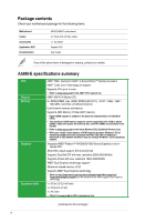
for the following items. Motherboard Cables Accessories Application DVD Documentation ASUS A58M-E motherboard 2 x Serial ATA 3.0 Gb/s cables 1 x I/O Shield Support DVD User Guide If any of the above items is damaged or missing, contact your retailer. A58M-E specifications summary CPU Chipset - Asus A58M-E R2.0 | User Guide - Page 7
Gigabit LAN controller Realtek® ALC887-VD 7.1-channel High Definition Audio CODEC • Use a chassis with HD audio module in the front panel to support a 7.1-channel audio output. AMD® A58 FCH: - 8 x USB 2.0/1.1 ports (4 ports at the mid-board, 4 ports at the back panel) ASUS 5X Protection - ASUS - Asus A58M-E R2.0 | User Guide - Page 8
DVI-D port 1 x D-Sub output port 1 x LAN (RJ-45) port 4 x USB 2.0/1.1 ports 7.1-channel audio I/O ports (3-jack) 2 x USB 2.0 connectors support additional 4 USB 2.0 ports 6 x SATA 3.0Gb/s connectors 1 x COM connector 1 x TPM header 1 x System panel connector 1 x Internal Speaker connector 1 x 4-pin - Asus A58M-E R2.0 | User Guide - Page 9
Product introduction 1 1.1 Before you proceed Take note of the following precautions before you install motherboard components or change any motherboard settings. • Unplug the power cord from the wall socket before touching any component. • Before handling components, use a grounded wrist strap - Asus A58M-E R2.0 | User Guide - Page 10
Place this side towards the rear of the chassis A58M-E 1.2.3 Motherboard layout 1 2 3 4 18.3cm(7.2in) KBMS ATX12V DIGI +VRM CPU_FAN CHA_FAN DDR3 DIMM_A1 (64bit, 240-pin module) DDR3 DIMM_B1 (64bit, 240-pin module) SOCKET FM2+ DVI_VGA 22.6cm(8.9in) 1-2 USB1112 EATXPWR LAN_USB12 1 - Asus A58M-E R2.0 | User Guide - Page 11
Connectors/Jumpers/Slots/LED 1. ATX power connectors (24-pin EATXPWR, 4-pin ATX12V) 2. AMD FM2+ socket 3. CPU and chassis fan connectors (4-pin CPU_FAN and 4-pin CHA_FAN) 4. DDR3 DIMM slots 5. Speaker connector (4-pin SPEAKER) 6. SATA 3.0Gb/s connectors (7-pin SATA3G_1~6) 7. System panel connector ( - Asus A58M-E R2.0 | User Guide - Page 12
1.3.1 Installing the APU 1 2 3 4 1.3.2 APU heatsink and fan assembly installation Apply the Thermal Interface Material to the APU heatsink and APU before you install the heatsink and fan if necessary. 1-4 Chapter 1: Product introduction - Asus A58M-E R2.0 | User Guide - Page 13
To install the APU heatsink and fan assembly 1 2 3 4 5 To uninstall the APU heatsink and fan assembly 1 2 3 ASUS A58M-E 1-5 - Asus A58M-E R2.0 | User Guide - Page 14
4 5 1.4 System memory 1.4.1 Overview The motherboard comes with two Double Data Rate 3 (DDR3) Dual Inline Memory Modules (DIMM) sockets. A DDR3 module has the same physical dimensions as a DDR2 DIMM but is notched differently to prevent installation on a DDR2 DIMM socket. DDR3 modules are - Asus A58M-E R2.0 | User Guide - Page 15
at the vendor-marked or at a higher frequency, refer to section 2.5 Ai Tweaker menu for manual memory frequency adjustment. • For system stability, use a more efficient memory cooling system to support a full memory load (2 DIMMs) or overclocking condition. • Refer to www.asus.com for the latest - Asus A58M-E R2.0 | User Guide - Page 16
1.4.3 1 Installing a DIMM 2 3 To remove a DIMM B A 1-8 A Chapter 1: Product introduction - Asus A58M-E R2.0 | User Guide - Page 17
Assign an IRQ to the card. 3. Install the software drivers for the expansion card. When using PCI cards on shared slots, ensure that the drivers support "Share IRQ" or that the cards do not need IRQ assignments. Otherwise, conflicts will arise between the two PCI groups, making the system unstable - Asus A58M-E R2.0 | User Guide - Page 18
PCI Express 2.0 x1 network cards, SCSI cards, and other cards that comply with the PCI Express specifications. 1.5.5 PCI Express x16 slot This motherboard supports one PCI Express 3.0/2.0 x16 graphics cards that comply with the PCI Express specifications. IRQ assignments for this motherboard - Asus A58M-E R2.0 | User Guide - Page 19
To erase the RTC RAM: 1. Turn OFF the computer and unplug the power cord. 2. Move the jumper cap from pins 1-2 (default) to pins 2-3. Keep the cap on pins 2-3 for about 5-10 seconds, then move the cap back to pins 1-2. 3. Plug the power cord and turn ON the computer. 4. Hold down the key - Asus A58M-E R2.0 | User Guide - Page 20
Out Bass/Center Side Speaker Out To configure a 7.1-channel audio output: Use a chassis with HD audio module in the front panel to support a 7.1-channel audio output. 7. USB 2.0 ports 1 and 2. These two 4-pin Universal Serial Bus (USB) ports are for USB 2.0/1.1 devices. 8. USB 2.0 ports 11 and - Asus A58M-E R2.0 | User Guide - Page 21
a CPU fan of maximum 2A (24 W) fan power. • The CPU_FAN and CHA_FAN connectors support the ASUS Fan Xpert feature. 2. TPM connector (20-1 pin TPM) This connector supports a Trusted Platform Module (TPM) system, which can securely store keys, digital certificates, passwords, and data. A TPM system - Asus A58M-E R2.0 | User Guide - Page 22
is inadequate. • If you are uncertain about the minimum power supply requirement for your system, refer to the Recommended Power Supply Wattage Calculator at http://support.asus. com/PowerSupplyCalculator/PSCalculator.aspx?SLanguage=en-us for details. 1-14 Chapter 1: Product introduction - Asus A58M-E R2.0 | User Guide - Page 23
create a Serial ATA RAID set using these connectors, set the type of the SATA connectors in the BIOS to [RAID]. • You must install Windows® XP Service Pack 3 or later version before using Serial ATA hard disk drives. The Serial ATA RAID feature is available only if you are using Windows® XP - Asus A58M-E R2.0 | User Guide - Page 24
6. System panel connector (10-1 pin PANEL) This connector supports several chassis-mounted functions. F_PANEL +PWR LED PWR BTN PWR_LED+ PWR_LEDPWR GND HDD_LED+ HDD_LED- Ground HWRST# (NC) A58M-E PIN 1 +HDD_LED RESET A58M-E System panel connector • - Asus A58M-E R2.0 | User Guide - Page 25
7. Front panel audio connector (10-1 pin AAFP) This connector is for a chassis-mounted front panel audio I/O module that supports either High Definition Audio or AC`97 audio standard. Connect one end of the front panel audio I/O module cable to this connector. AGND NC SENSE1_RETUR - Asus A58M-E R2.0 | User Guide - Page 26
of these connectors, then install the module to a slot opening at the back of the system chassis. These USB connectors comply with USB 2.0 specification that supports up to 480Mbps connection speed. USB56 USB34 USB+5V USB_P5USB_P5+ GND NC USB+5V USB_P3USB_P3+ GND NC A58M-E PIN 1 PIN 1 USB+5V - Asus A58M-E R2.0 | User Guide - Page 27
Service Pack 3 or later versions before installing the drivers for better compatibility and system stability. 1.8.2 Support DVD information The Support Manual, Contact and Specials tabs to display their respective menus. The following screen is for reference only. Click an icon to display Support - Asus A58M-E R2.0 | User Guide - Page 28
1-20 Chapter 1: Product introduction - Asus A58M-E R2.0 | User Guide - Page 29
update your motherboard's softwares, drivers and the BIOS version easily. With this utlity, you can also manually update the saved BIOS and select a boot logo when the system goes into POST. To launch EZ connection either through a network or an ISP (Internet Service Provider). ASUS A58M-E 2-1 - Asus A58M-E R2.0 | User Guide - Page 30
process. Reboot the system when the update process is done. • This function supports USB flash disks with FAT 32/16 format and single partition only. • updating process. You can restore a corrupted BIOS file using the motherboard support DVD or a USB flash drive that contains the updated BIOS file. - Asus A58M-E R2.0 | User Guide - Page 31
DVD and a USB flash drive. • Download the latest BIOS file and BIOS Updater from http://support.asus.com and save them in your USB flash drive. NTFS is not supported under FreeDOS environment. Ensure that your USB flash drive is in single partition and in FAT32/16 format. • Turn off the computer - Asus A58M-E R2.0 | User Guide - Page 32
Please select boot device: E1: ASUS DVD-E818A6T (4069MB) USB DISK 2.0 (3824MB) UEFI: (FAT) USB DISK 2.0 (3824MB) Enter Setup and to move selection ENTER to select boot device ESC to boot using defaults 4. When the booting message appears, press within five (5) seconds to enter FreeDOS - Asus A58M-E R2.0 | User Guide - Page 33
file, select Yes to confirm the BIOS update. Are you sure you want to update the BIOS? Yes No The BIOS Backup feature is not supported due to security regulations. 5. Select Yes then press . When BIOS update is done, press to exit BIOS Updater. 6. Restart your computer. DO NOT - Asus A58M-E R2.0 | User Guide - Page 34
program Use the BIOS Setup program to update the BIOS or configure its parameters. The BIOS screens include navigation keys and brief online help to guide you in using the BIOS Setup program. Entering BIOS Setup at startup To enter BIOS Setup at startup: • Press during the Power-On Self - Asus A58M-E R2.0 | User Guide - Page 35
EZ Mode By default, the EZ Mode screen appears when you enter the BIOS setup program. The EZ Mode provides you an overview of the basic system information, and allows you to select the display language, system performance mode and boot device priority. To access the Advanced Mode, click Exit/ - Asus A58M-E R2.0 | User Guide - Page 36
Advanced Mode The Advanced Mode provides advanced options for experienced end-users to configure the BIOS settings. The figure below shows an example of the Advanced Mode. Refer to the following sections for the detailed configurations. To access the EZ Mode, click Exit, then select ASUS EZ Mode or - Asus A58M-E R2.0 | User Guide - Page 37
2.3 My Favorites MyFavorites is your personal space where you can easily save and access your favorite BIOS items. Adding items to My Favorites To add frequently-used BIOS items to My Favorites: 1. Use the arrow keys to select an item that you want to add. When using a mouse, hover the pointer to - Asus A58M-E R2.0 | User Guide - Page 38
2.4 Main menu The Main menu screen appears when you enter the Advanced Mode of the BIOS Setup program. The Main menu provides you an overview of the basic system information, and allows you to set the system date, time, language, and security settings. • If you have forgotten your BIOS password, - Asus A58M-E R2.0 | User Guide - Page 39
2.5 Ai Tweaker menu The Ai Tweaker menu items allow you to configure overclocking-related items. Be cautious when changing the settings of the Ai Tweaker menu items. Incorrect field values can cause the system to malfunction. The configuration options for this section vary depending on the CPU and - Asus A58M-E R2.0 | User Guide - Page 40
2.6 Advanced menu The Advanced menu items allow you to change the settings for the CPU and other system devices. Be cautious when changing the settings of the Advanced menu items. Incorrect field values can cause the system to malfunction. 2.7 Monitor menu The Monitor menu displays the system - Asus A58M-E R2.0 | User Guide - Page 41
2.8 Boot menu The Boot menu items allow you to change the system boot options. Scroll down to display the other items. ASUS A58M-E 2-13 - Asus A58M-E R2.0 | User Guide - Page 42
2.9 Tools menu The Tools menu items allow you to configure options for special functions. Select an item then press to display the submenu. 2.10 Exit menu The Exit menu items allow you to load the optimal default values for the BIOS items, and save or discard your changes to the BIOS items. - Asus A58M-E R2.0 | User Guide - Page 43
. This equipment generates, uses and can radiate radio frequency energy and, if not installed and used in accordance with manufacturer's instructions, may cause harmful interference to radio communications. However, there is no guarantee that interference will not occur in a particular installation - Asus A58M-E R2.0 | User Guide - Page 44
IC: Canadian Compliance Statement Complies with the Canadian ICES-003 Class B specifications. This device complies with RSS 210 of Industry Canada. This Class B device meets all the requirements of the Canadian interference-causing equipment regulations. This device complies with Industry Canada - Asus A58M-E R2.0 | User Guide - Page 45
. This symbol of the crossed out wheeled bin indicates that the battery should not be placed in municipal waste. ASUS Recycling/Takeback Services ASUS recycling and takeback programs come from our commitment to the highest standards for protecting our environment. We believe in providing solutions - Asus A58M-E R2.0 | User Guide - Page 46
510-739-3777 Fax +1-510-608-4555 Web site http://www.asus.com/us/ Technical Support General support Support fax Online support +1-812-282-2787 +1-812-284-0883 http://www.service.asus.com/ ASUS COMPUTER GmbH (Germany and Austria) Address Fax Web site Online contact - Asus A58M-E R2.0 | User Guide - Page 47
A-5 ASUS A58M-E DECLARATION OF CONFORMITY Per FCC Part 2 Section 2. 1077(a) Responsible Party Name: Asus Computer International Address: 800 Corporate Way, Fremont, CA 94539. Phone/Fax No: (510)739-3777/(510)608-4555 hereby declares that the product Product Name : Motherboard Model Number : A58M
-
 1
1 -
 2
2 -
 3
3 -
 4
4 -
 5
5 -
 6
6 -
 7
7 -
8
-
9
-
10
-
11
-
12
-
13
-
14
-
15
-
16
-
17
-
18
-
19
-
20
-
21
-
22
-
23
-
24
-
25
-
26
-
27
-
28
-
29
-
30
-
31
-
32
-
33
-
34
-
35
-
36
-
37
-
38
-
39
-
40
-
41
-
42
-
43
-
44
-
45
-
46
-
47
 |
 |

Motherboard
A58M-E