Asus AP1600R-E2AI2 AP1600R-E2 AA2AI2 Users Manual English version 20 E1962
Asus AP1600R-E2AI2 Manual
 |
View all Asus AP1600R-E2AI2 manuals
Add to My Manuals
Save this manual to your list of manuals |
Asus AP1600R-E2AI2 manual content summary:
- Asus AP1600R-E2AI2 | AP1600R-E2 AA2AI2 Users Manual English version 20 E1962 - Page 1
AP1600R-E2 (AA2/AI2) 1U Rackmount Barebone Server User Guide - Asus AP1600R-E2AI2 | AP1600R-E2 AA2AI2 Users Manual English version 20 E1962 - Page 2
. ASUS assumes no responsibility or liability for any errors or inaccuracies that may appear in this manual, including the products and software described in it. Product warranty or service will not be extended if: (1) the product is repaired, modified or altered, unless such repair, modification - Asus AP1600R-E2AI2 | AP1600R-E2 AA2AI2 Users Manual English version 20 E1962 - Page 3
Contents Notices vii Safety information viii About this guide ix Chapter 1: Product introduction 1-1 1.1 System package contents 1-2 1.2 System specifications 1-3 1.3 Front panel features 1-4 1.4 Rear panel features 1-5 1.5 Internal features 1-6 1.6 LED information 1-7 1.6.1 Front panel - Asus AP1600R-E2AI2 | AP1600R-E2 AA2AI2 Users Manual English version 20 E1962 - Page 4
2.7.3 Power supply module 2-20 2.7.4 Optical drive 2-21 2.7.5 Motherboard 2-23 2.8 SATA backplane cabling (for AA2 2-26 2.9 Fan control board cabling (for AI2 2-27 Chapter 3: Installation options 3-1 3.1 Rackmount rail kit items 3-2 3.2 Rack rails assembly 3-2 3.3 Attaching the rails to the - Asus AP1600R-E2AI2 | AP1600R-E2 AA2AI2 Users Manual English version 20 E1962 - Page 5
5.4 Advanced menu 5-21 5.4.1 Advanced BIOS Features 5-22 5.4.2 CPU Configuration 5-23 5.4.3 Memory Configuration 5-24 5.4.4 Chipset 5-25 5.4.5 Onboard Device 5-26 5.4.6 PCIPnP 5-30 5.4.7 USB Configuration 5-32 5.5 Power menu 5-33 5.5.1 APM Configuration 5-34 5.5.2 Hardware Monitor 5-37 - Asus AP1600R-E2AI2 | AP1600R-E2 AA2AI2 Users Manual English version 20 E1962 - Page 6
. This equipment generates, uses and can radiate radio frequency energy and, if not installed and used in accordance with manufacturer's instructions, may cause harmful interference to radio communications. However, there is no guarantee that interference will not occur in a particular installation - Asus AP1600R-E2AI2 | AP1600R-E2 AA2AI2 Users Manual English version 20 E1962 - Page 7
to fix it by yourself. Contact a qualified service technician or your dealer. Operation Safety • Any the server, carefully read all the manuals included with the server package. • Dispose of used batteries according to the manufacturer's instructions. CD-ROM Drive Safety Warning CLASS 1 LASER - Asus AP1600R-E2AI2 | AP1600R-E2 AA2AI2 Users Manual English version 20 E1962 - Page 8
with at least basic knowledge of configuring a server. Contents This guide contains the following parts: 1. Chapter 1: Product Introduction This chapter parameters. 6. Chapter 6: Driver installation This chapter provides instructions for creating and configuring RAID, and installing the necessary - Asus AP1600R-E2AI2 | AP1600R-E2 AA2AI2 Users Manual English version 20 E1962 - Page 9
components when trying to complete a task. I M P O R T A N T : Instructions that you MUST follow to complete a task. N O T E : Tips and information to guide This manual contains detailed information about the ASUS NCCH-DR motherboard. 2. ASUS Server Web-based Management (ASWM) user guide This manual - Asus AP1600R-E2AI2 | AP1600R-E2 AA2AI2 Users Manual English version 20 E1962 - Page 10
x - Asus AP1600R-E2AI2 | AP1600R-E2 AA2AI2 Users Manual English version 20 E1962 - Page 11
Product introduction Chapter 1 This chapter describes the general features of the chassis kit. It includes sections on front panel and rear panel specifications. ASUS AP1600R-E2 (AA2/AI2) 1-1 - Asus AP1600R-E2AI2 | AP1600R-E2 AA2AI2 Users Manual English version 20 E1962 - Page 12
Rackmount rail kit Bundled CDs • AP1600R-E2 drivers and utilities CD • CA Anti-virus software CD User guide AA2 model AI2 model * AA2 model - supports up to two hot-swap SATA hard disks * AI2 model - supports up to two internal IDE hard disks, or up to two internal SATA hard disks Contact your - Asus AP1600R-E2AI2 | AP1600R-E2 AA2AI2 Users Manual English version 20 E1962 - Page 13
memory architecture Intel® PRO/1000 CT Network Connection (82547GI) Intel® PRO/1000 MT Network Connection (82541GI) ATI RAGE-XL PCI-based VGA controller Supports 8MB display memory 1 x PCI-X 66 MHz/64-bit slot (PCI-X 1.0) 1 x Mini-PCI socket for the ASUS Server Management Board Intel® 6300ESB South - Asus AP1600R-E2AI2 | AP1600R-E2 AA2AI2 Users Manual English version 20 E1962 - Page 14
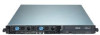
1.3 Front panel features The barebone server displays a simple yet stylish front panel with easily accessible features. The power and reset buttons, LED indicators, location switch, optical drive, and two USB ports are located on the front panel. Refer to section "1.6.1 Front panel LEDs" for the LED - Asus AP1600R-E2AI2 | AP1600R-E2 AA2AI2 Users Manual English version 20 E1962 - Page 15
1-5 1.4 Rear panel features The rear panel includes the expansion slot, system power socket, and rear fans. The middle part includes the I/O shield with openings for the rear panel connectors on the motherboard. The ports for the PS/2 keyboard, PS/2 mouse, USB, VGA, and Gigabit LAN do not appear on - Asus AP1600R-E2AI2 | AP1600R-E2 AA2AI2 Users Manual English version 20 E1962 - Page 16
1.5 Internal features The barebone server includes the basic components as shown. The AA2 and AI2 models have the same internal features except for the SATA backplane, fan control board, and HDD trays. AA2 model 2 1 3 4 AI2 model 5 6 7 10 8 9 7 8 9 1. PCI-X riser card bracket 7. A A - Asus AP1600R-E2AI2 | AP1600R-E2 AA2AI2 Users Manual English version 20 E1962 - Page 17
1.6 LED information 1.6.1 Front panel LEDs HDD Access LED Power LED LAN2 LED Location LED Message LED LAN1 LED LED Power LED HDD Access LED Message LED Location LED Display status ON OFF Blinking OFF Blinking OFF ON LAN LEDs OFF Blinking ON Description System power ON No activity Read/ - Asus AP1600R-E2AI2 | AP1600R-E2 AA2AI2 Users Manual English version 20 E1962 - Page 18
1-8 Chapter 1: Product introduction - Asus AP1600R-E2AI2 | AP1600R-E2 AA2AI2 Users Manual English version 20 E1962 - Page 19
Chapter 2 This chapter lists the hardware setup procedures that you have to perform when installing or removing system components. Hardware setup ASUS AP1600R-E2 (AA2/AI2) 2-1 - Asus AP1600R-E2AI2 | AP1600R-E2 AA2AI2 Users Manual English version 20 E1962 - Page 20
2.1 Chassis cover 2.1.1 Removing the cover 1. Use a Phillips screwdriver to remove the screw on each front end of the top cover. 2. Loosen the two thumbscrews on the rear panel to release the top cover from the chassis. 3. Firmly hold the cover and slide it toward the rear panel for about half an - Asus AP1600R-E2AI2 | AP1600R-E2 AA2AI2 Users Manual English version 20 E1962 - Page 21
2.1.2 Installing the cover 1. Position the cover on top of the chassis with the thumbscrews on the rear, and leaving a gap of about half an inch from the front panel. Side markings 2. Make sure that the side markings on the cover (two on each side) are aligned to the grooves on the chassis. Grooves - Asus AP1600R-E2AI2 | AP1600R-E2 AA2AI2 Users Manual English version 20 E1962 - Page 22
) socket and designed for the Intel® Xeon™ processors. Intel Xeon Gold Arrow CPU2 Pin A1 CPU1 NCCH-DR NCCH-DR CPU Socket 604 1. The motherboard supports either one or two CPUs. If you are installing only one CPU, you MUST install it in CPU socket 1. 2. If you are installing two CPUs - Asus AP1600R-E2AI2 | AP1600R-E2 AA2AI2 Users Manual English version 20 E1962 - Page 23
2. Carefully insert the CPU into the socket as shown until it fits in place. The CPU fits only in one correct orientation. DO NOT force the CPU into the socket to prevent bending the pins and damaging the CPU! 3. Carefully push down the socket lever to secure the CPU. The lever clicks on the side - Asus AP1600R-E2AI2 | AP1600R-E2 AA2AI2 Users Manual English version 20 E1962 - Page 24
2.2.2 Installing the CPU heatsink To install the CPU heatsink: 1. Carefully place the heatsink on top of the installed CPU. 2. Twist each of the four screws with a Philips (cross) screwdriver just enough to attach the heatsink to the motherboard. When the four screws are attached, tighten them one - Asus AP1600R-E2AI2 | AP1600R-E2 AA2AI2 Users Manual English version 20 E1962 - Page 25
chipset resource allocation, the system may detect less than 8 GB system memory when you install four 2 GB DDR memory modules. • This motherboard does not support memory modules made up of 128 Mb chips or double sided x16 memory modules. • Three DDR DIMMs intalled into any three memory sockets will - Asus AP1600R-E2AI2 | AP1600R-E2 AA2AI2 Users Manual English version 20 E1962 - Page 26
Clip 2.4.4 Removing a DIMM Follow these steps to remove a DIMM. 2 1. Simultaneously press the retaining clips outward to unlock the DIMM. 1 1 DDR DIMM notch Support the DIMM lightly with your fingers when pressing the retaining clips. The DIMM might get damaged when it flips out with extra - Asus AP1600R-E2AI2 | AP1600R-E2 AA2AI2 Users Manual English version 20 E1962 - Page 27
2.4 Hard disk drives 2.4.1 Installing a hot-swap SATA HDD (AA2 model) To install a hot-swap SATA HDD: 1. Release a drive tray by pushing the spring lock to the right, then pulling the tray lever outward. The drive tray ejects slightly after you pull out the lever. 2. Firmly hold the tray lever and - Asus AP1600R-E2AI2 | AP1600R-E2 AA2AI2 Users Manual English version 20 E1962 - Page 28
5. Carefully insert the drive tray and push it all the way to the depth of the bay until just a small fraction of the tray edge protrudes. SATA interface on the backplane When installed, the SATA connector on the drive connects to the SATA interface on the backplane. 6. Push the tray lever until - Asus AP1600R-E2AI2 | AP1600R-E2 AA2AI2 Users Manual English version 20 E1962 - Page 29
2.4.2 Installing an IDE HDD (AI2 model) To install an IDE HDD: 1. Disconnect all the cables from the fan control board. Use a Phillips (cross) screwdriver to remove the five screws that secure the fan control board. Fan control board screws 2. Remove the screw that secures the hard disk tray to the - Asus AP1600R-E2AI2 | AP1600R-E2 AA2AI2 Users Manual English version 20 E1962 - Page 30
4. Carefully place the tray with installed hard disk drive into the drive bay. Slide it forward until the front end aligns with the front panel, and the screw hole matches the standoff. 5. Secure the tray with a screw. 6. Repeat steps 2 to 5 if you wish to install a second HDD; otherwise, proceed to - Asus AP1600R-E2AI2 | AP1600R-E2 AA2AI2 Users Manual English version 20 E1962 - Page 31
2.4.3 Installing an internal SATA HDD (AI2 model) To install an internal SATA HDD: 1. Follow steps 1 to 7 in section "2.4.2 Installing an IDE hard disk drive." 2. Connect the 7-pin SATA cable to the SATA connector on the back of the drive. Connect the other end to an SATA connector on the - Asus AP1600R-E2AI2 | AP1600R-E2 AA2AI2 Users Manual English version 20 E1962 - Page 32
2.5 Expansion slot 2.5.1 Installing an expansion card The barebone server comes with a riser card bracket. You need to remove the bracket if you wish to install a PCI-X expansion card. To install a PCI-X card: 1. Use a Phillips (cross) screwdriver to remove the screw that secures the riser card to - Asus AP1600R-E2AI2 | AP1600R-E2 AA2AI2 Users Manual English version 20 E1962 - Page 33
5. Take note of the holes on the riser card bay. The two pegs on the riser card bracket should match these holes to ensure that the bracket is properly in place. Peg on the riser card bracket 6. Install the riser card bracket with the card into the PCI-X slot on the motherboard. 7. Make sure that - Asus AP1600R-E2AI2 | AP1600R-E2 AA2AI2 Users Manual English version 20 E1962 - Page 34
PXIRQ1 INTC# - - PXIRQ2 INTD# - - PXIRQ3 REQ# REQ2# REQ3# X_REQ0 GNT# GNT2# GNT3# X_GNT0 When using PCI cards on shared slots, ensure that the drivers support "Share IRQ" or that the cards do not need IRQ assignments. Otherwise, conflicts will arise between the two PCI groups, making the system - Asus AP1600R-E2AI2 | AP1600R-E2 AA2AI2 Users Manual English version 20 E1962 - Page 35
2.6 Cable connections AA2 model 2 3 1 4 5 6 7 8 10 9 Pre-connected system cables 1. Parallel port cable (from motherboard to rear panel) 2. Rear fan connector (from power supply to motherboard) 3. 24-pin SSI power connector (from power supply to motherboard) 4. 8-pin SSI power connector ( - Asus AP1600R-E2AI2 | AP1600R-E2 AA2AI2 Users Manual English version 20 E1962 - Page 36
AI2 model 3 1 2 4 5 6 78 9 Pre-connected system cables 1. Parallel port cable (from motherboard to rear panel) 2. Rear fan connector (from power supply to motherboard) 3. 24-pin SSI power connector (from power supply to motherboard) 4. 8-pin SSI power connector (power supply to motherboard) - Asus AP1600R-E2AI2 | AP1600R-E2 AA2AI2 Users Manual English version 20 E1962 - Page 37
2.7 Removable components You may need to remove previously installed system components when installing or removing system devices, or when you need to replace defective components. This section tells how to remove the following components: 1. System fans 2. Device fan 3. Power supply module 4. - Asus AP1600R-E2AI2 | AP1600R-E2 AA2AI2 Users Manual English version 20 E1962 - Page 38
2.7.3 Power supply module To uninstall the power supply module: 1. Disconnect all the power cables connected to the motherboard and other system devices. 2. Use a Phillips (cross) screwdriver to remove the screw the secures the front end of the power supply. 3. Slide the power supply backward for - Asus AP1600R-E2AI2 | AP1600R-E2 AA2AI2 Users Manual English version 20 E1962 - Page 39
2.7.4 Optical drive To uninstall the optical drive: 1. Please use a pin-ejector (paper clipper may be used) for trayout.. (or you can open the tray by pushing the "open botton") When changing ODD, the black ODD front plastic housing is already removed. User can uninstall/install ODD after remove the - Asus AP1600R-E2AI2 | AP1600R-E2 AA2AI2 Users Manual English version 20 E1962 - Page 40
To install an optical drive: 1. Please follow previous Step 1 instructions to tray-out and to remove the ODD bezel. 2. Then put the ODD inside the server and insert ODD into the ODD bay. The purpose - Asus AP1600R-E2AI2 | AP1600R-E2 AA2AI2 Users Manual English version 20 E1962 - Page 41
from the motherboard including the CPU and heatsink, riser card bracket, and DDR DIMMs. Refer to the corresponding sections for instructions on removing these components. 3. Remove the riser card standoff by twisting it counterclockwise. Riser card standoff 3. Use a Phillips (cross) screwdriver - Asus AP1600R-E2AI2 | AP1600R-E2 AA2AI2 Users Manual English version 20 E1962 - Page 42
To reinstall the motherboard: 1. Firmly hold the motherboard by the sides and insert it into the chassis as shown. 2. Carefully adjust the motherboard until the rear panel ports fit in place. 3. Use a Phillips (cross) screwdriver to secure the motherboard with nine (9) screws in the holes as shown. - Asus AP1600R-E2AI2 | AP1600R-E2 AA2AI2 Users Manual English version 20 E1962 - Page 43
4. Insert the riser card standoff into the motherboard hole beside the PCI-X slot, and twist it clockwise until secure. 5. Reconnect all the required cables to the motherboard. See section "2.6 Cable connections" for illustration. 6. Reinstall all the devices that you have previously removed. ASUS - Asus AP1600R-E2AI2 | AP1600R-E2 AA2AI2 Users Manual English version 20 E1962 - Page 44
2.8 SATA backplane cabling (for AA2) Connects the SMBus cable from the MB Connect the SATA cables from the MB (FAN1) Connects the fan cable from CPU_FAN1 on the MB Connect the system fan cables Connects the device fan cable Connect the SATA HDDs Connects a 4-pin plug from power supply 2-26 - Asus AP1600R-E2AI2 | AP1600R-E2 AA2AI2 Users Manual English version 20 E1962 - Page 45
2.9 Fan control board cabling (for AI2) Connects the SMBus cable from the MB (FAN1) Connects the fan cable from CPU_FAN1 on the MB Connect the system fan cables Connects the device fan cable Connects a 4-pin plug from power supply ASUS AP1600R-E2 (AA2/AI2) 2-27 - Asus AP1600R-E2AI2 | AP1600R-E2 AA2AI2 Users Manual English version 20 E1962 - Page 46
2-28 Chapter 2: Hardware setup - Asus AP1600R-E2AI2 | AP1600R-E2 AA2AI2 Users Manual English version 20 E1962 - Page 47
Installation options Chapter 3 This chapter describes how to install the optional components and devices into the barebone server. ASUS AP1600R-E2 (AA2/AI2) 2-1 - Asus AP1600R-E2AI2 | AP1600R-E2 AA2AI2 Users Manual English version 20 E1962 - Page 48
3.1 Rackmount rail kit items If you have the rackmount rail kit, it contains two pairs of rails (one pair for each side of the barebone system), and eight (8) pairs of nut-and-bolt type screws. Nuts Bolts Left pair Right pair 3.2 Rack rails assembly To assemble the rack rails: 1. Determine the - Asus AP1600R-E2AI2 | AP1600R-E2 AA2AI2 Users Manual English version 20 E1962 - Page 49
3.3 Attaching the rails to the rack To attach the rails to the rack: 1. Select one unit of space (1U) on the rack where you wish to install the barebone server. 2. Remove the screws from the 1U space on the rack front. 3. Align the front end holes of a rack rail pair to the 1U space. 4. Drive in - Asus AP1600R-E2AI2 | AP1600R-E2 AA2AI2 Users Manual English version 20 E1962 - Page 50
3.4 Rackmounting the server To mount the server to the rack: 1. Firmly hold the server on both sides and insert the rear panel side to the front end of the rack rail, then carefully push the server all the way to the back until the front panel fits the front end of the rack, and the rack screws on - Asus AP1600R-E2AI2 | AP1600R-E2 AA2AI2 Users Manual English version 20 E1962 - Page 51
Motherboard info Chapter 4 This chapter includes the motherboard layout, and brief descriptions of the jumpers and internal connectors. ASUS AP1600R-E2 (AA2/AI2) - Asus AP1600R-E2AI2 | AP1600R-E2 AA2AI2 Users Manual English version 20 E1962 - Page 52
mPGA 604 30.5cm (12in) 4.1 Motherboard layout mPGA 604 PS/2KBMS T: Mouse KBPWR1 B: Keyboard ATXPWR1 USB12 PSUSMB1 USBPW12 COM1 REAR_FAN2 LAN_EN1 Intel 82547GI Gigabit Ethernet 26.8cm (10.5in) ATX12V1 Intel MCH E7210 CPU2 VGA LAN1 DDR DIMM_A1 (64 bit,184-pin module) DDR DIMM_A2 (64 bit, - Asus AP1600R-E2AI2 | AP1600R-E2 AA2AI2 Users Manual English version 20 E1962 - Page 53
Layout contents Slots 1. CPU sockets 2. DDR DIMM sockets 3. PCI/PCI-X slots Page 2-13 2-16 2-20 Jumpers Clear RTC RAM (CLRTC1) CPU fan pin selection (3-pin FM_CPU1, FM_CPU2) USB device wake-up (3-pin USBPW12, USBPW34) Keyboard power (3-pin KBPWR1) SATA controller setting (3-pin SATA_EN1) SATA - Asus AP1600R-E2AI2 | AP1600R-E2 AA2AI2 Users Manual English version 20 E1962 - Page 54
Internal connectors Floppy disk drive connector (34-1 pin FLOPPY) IDE connectors (40-1 pin PRI_IDE, SEC_IDE) Serial ATA connectors (7-pin SATA1, SATA2) Serial ATA RAID connectors (7-pin SATA_RAID1, SATA_RAID2, SATA_RAID3, SATA_RAID4) SATA models only Hard disk activity LED connector (2-pin HDLED) - Asus AP1600R-E2AI2 | AP1600R-E2 AA2AI2 Users Manual English version 20 E1962 - Page 55
4.2 Jumpers 1. Clear RTC RAM (CLRTC1) This jumper allows you to clear the Real Time Clock (RTC) RAM in CMOS. You can clear the CMOS memory of date, time, and system setup parameters by erasing the CMOS RTC RAM data. The onboard button cell battery powers the RAM data in CMOS, which include system - Asus AP1600R-E2AI2 | AP1600R-E2 AA2AI2 Users Manual English version 20 E1962 - Page 56
2. CPU fan pin selection (3-pin FM_CPU1, FM_CPU2) These jumpers allow you to connect either a 3-pin or a 4-pin CPU fan cable plug to the CPU fan connectors (CPU_FAN1, CPU_FAN2). Set these jumpers to pins 1-2 if you are using a 3-pin fan cable plug, or to pins 2-3 if you are using a 4-pin plug. NCCH - Asus AP1600R-E2AI2 | AP1600R-E2 AA2AI2 Users Manual English version 20 E1962 - Page 57
4. Keyboard power (3-pin KBPWR1) This jumper allows you to enable or disable the keyboard wake-up feature. Set this jumper to pins 2-3 (+5VSB) to wake up the computer when you press a key on the keyboard (the default is the Space Bar). This feature requires an ATX power supply that can supply at - Asus AP1600R-E2AI2 | AP1600R-E2 AA2AI2 Users Manual English version 20 E1962 - Page 58
6. Gigabit LAN2 controller setting (3-pin LAN_EN2) This jumper allows you to enable or disable the Intel® 82541GI Gigabit LAN controller (32-bit) that controls the LAN2 port. Place a jumper cap on pins 1-2 to activate the Gigabit LAN2 controller. NCCH-DR NCCH-DR LAN_EN2 setting LAN_EN2 12 23 - Asus AP1600R-E2AI2 | AP1600R-E2 AA2AI2 Users Manual English version 20 E1962 - Page 59
8. Force BIOS recovery (3-pin RECOVERY) This jumper allows you to update or recover the BIOS settings when it gets corrupted or destroyed.This jumper allows you to update/recover the BIOS quickly. To update the BIOS: 1. Prepare a floppy disk that contains the latest BIOS for the motherboard (xxxx- - Asus AP1600R-E2AI2 | AP1600R-E2 AA2AI2 Users Manual English version 20 E1962 - Page 60
4.3 Connectors 1. Floppy disk drive connector (34-1 pin FLOPPY) This connector is for the provided floppy disk drive (FDD) signal cable. Insert one end of the cable to this connector, then connect the other end to the signal connector at the back of the floppy disk drive. Pin 5 on the connector is - Asus AP1600R-E2AI2 | AP1600R-E2 AA2AI2 Users Manual English version 20 E1962 - Page 61
RSATA_RXP2 GND SATA1 GND RSATA_TXP1 RSATA_TXN1 GND RSATA_RXN1 RSATA_RXP1 GND Important notes on Serial ATA • You must install Windows® 2000 Service Pack 4 or the Windows® XP Service Pack 1 before using Serial ATA hard disk drives. The Serial ATA RAID feature (RAID 0/RAID 1) is available only if you - Asus AP1600R-E2AI2 | AP1600R-E2 AA2AI2 Users Manual English version 20 E1962 - Page 62
# NC NCCH-DR NCCH-DR SCSI/SATA card activity LED connector 5. CPU and system fan connectors (4-pin CPU_FAN1/2, 3-pin REAR_FAN1/2, FRNT_FAN1/2) The fan connectors support cooling fans of 350 mA ~ 740 mA (8.88 W max.) or a total of 2.1 A ~ 4.44 A (53.28 W max.) at +12V. Connect the fan cables to the - Asus AP1600R-E2AI2 | AP1600R-E2 AA2AI2 Users Manual English version 20 E1962 - Page 63
6. USB port connector (10-1 pin USB34) This connector is for additional USB 2.0 ports. Connect the USB module cable to this connector, then install the module to a slot opening at the back of the system chassis. Never connect a 1 3 9 4 c a b l e to the USB connectors. Doing so will damage the - Asus AP1600R-E2AI2 | AP1600R-E2 AA2AI2 Users Manual English version 20 E1962 - Page 64
8 . S S I power connectors (24-pin ATXPWR1, 8- p i n A T X 1 2 V 1) These connectors are for SSI power supply plugs. The power supply plugs are designed to fit these connectors in only one orientation. Find the proper orientation and push down firmly until the connectors completely fit. • Use of an - Asus AP1600R-E2AI2 | AP1600R-E2 AA2AI2 Users Manual English version 20 E1962 - Page 65
AFD# ERROR# PINIT# SLIN# GND GND GND GND GND GND GND GND STB# SPD0 SPD1 SPD2 SPD3 SPD4 SPD5 SPD6 SPD7 ACK# BUSY PE SLCT 9. Printer port connector (26-1 pin LPT1) This connector is for a parallel printer port. Connect the parallel printer port module cable to this connector, then install the module - Asus AP1600R-E2AI2 | AP1600R-E2 AA2AI2 Users Manual English version 20 E1962 - Page 66
FAN_PWM I2C_6_CLK# GND I2C_6_DATA# +5V 11. Backplane SMBus connector (6-1 pin BPSMB1) This connector allows you to connect SMBus (System Management Bus) devices. Devices communicate with an SMBus host and/or other SMBus devices using the SMBus interface. BPSMB1 1 NCCH-DR NCCH-DR SMBus connector 12. - Asus AP1600R-E2AI2 | AP1600R-E2 AA2AI2 Users Manual English version 20 E1962 - Page 67
panel System Management bus (SMBus). AUX_PANEL1 1 NCCH-DR NCCH-DR Auxiliary panel connector 14. System panel connector (20-pin PANEL1) This connector supports several chassis-mounted functions. PANEL1 NCCH-DR NCCH-DR System panel connector The sytem panel connector is color-coded for easy connection - Asus AP1600R-E2AI2 | AP1600R-E2 AA2AI2 Users Manual English version 20 E1962 - Page 68
• System power LED (Green 3-pin PLED) This 3-pin connector is for the system power LED. Connect the chassis power LED cable to this connector. The system power LED lights up when you turn on the system power, and blinks when the system is in sleep mode. • Message LED (Brown 2-pin MLED) This - Asus AP1600R-E2AI2 | AP1600R-E2 AA2AI2 Users Manual English version 20 E1962 - Page 69
Chapter 5 This chapter lists the hardware setup procedures that you have to perform when installing or removing system components. BIOS setup ASUS AP1600R-E2 (AA2/AI2) 2-1 - Asus AP1600R-E2AI2 | AP1600R-E2 AA2AI2 Users Manual English version 20 E1962 - Page 70
when the BIOS file fails or gets corrupted.) 3. A S U S E Z F l a s h (Updates the BIOS in DOS mode using a floppy disk or the motherboard support CD.) 4. A S U S U p d a t e (Updates the BIOS in Windows® environment.) Refer to the corresponding sections for details on these utilities. Save a copy - Asus AP1600R-E2AI2 | AP1600R-E2 AA2AI2 Users Manual English version 20 E1962 - Page 71
then select R u n. d. In the O p e n field, type D:\bootdisk\makeboot a: assuming that D is your optical drive letter. e. Press , then follow screen instructions to continue. 2. Copy the original or the latest motherboard BIOS file to the bootable floppy disk. ASUS AP1600R-E2 (AA2/AI2) 5-3 - Asus AP1600R-E2AI2 | AP1600R-E2 AA2AI2 Users Manual English version 20 E1962 - Page 72
file in the floppy disk to avoid loading the wrong BIOS file. 2. Copy the AwardBIOS Flash Utility (awdflash.exe) from the Software folder of the support CD to the floppy disk with the latest BIOS file. 3. Boot the system in DOS mode using the bootable floppy disk you created earlier. 4. When - Asus AP1600R-E2AI2 | AP1600R-E2 AA2AI2 Users Manual English version 20 E1962 - Page 73
6. Type the BIOS file name in the File Name to Program field, then press . AwardBIOS Flash Utility for ASUS V1.05 (C) Phoenix Technologies Ltd. All Rights Reserved For Canterwood - NCCH-DRC-00 DATE: 07/14/2004 Flash Type - SST 49LF008A /3.3V File Name to Program : 1001.bin Message: Do - Asus AP1600R-E2AI2 | AP1600R-E2 AA2AI2 Users Manual English version 20 E1962 - Page 74
Copying the current BIOS file You can use the AwardBIOS Flash Utility to save the current BIOS file. You can load the current BIOS file when the BIOS file gets corrupted during the flashing process. To save the current BIOS file using the AwardBIOS Flash Utility: 1. Follow steps 1 to 6 of the - Asus AP1600R-E2AI2 | AP1600R-E2 AA2AI2 Users Manual English version 20 E1962 - Page 75
4. The utility saves the current BIOS file to the floppy disk, then returns to the BIOS flashing process. AwardBIOS Flash Utility for ASUS V1.05 (C) Phoenix Technologies Ltd. All Rights Reserved For Canterwood - NCCH-DRC-00 DATE: 07/14/2004 Flash Type - SST 49LF008A /3.3V File Name to Program : - Asus AP1600R-E2AI2 | AP1600R-E2 AA2AI2 Users Manual English version 20 E1962 - Page 76
and the AwardBIOS Flash Utility or the motherboard support CD. Prepare the floppy disk containing the updated motherboard BIOS : Message: Please input File Name! 4. Update the BIOS file following the instructions on the section "AwardBIOS Flash Utility". DO NOT shut down or reset the system - Asus AP1600R-E2AI2 | AP1600R-E2 AA2AI2 Users Manual English version 20 E1962 - Page 77
DATE: 07/14/2004 Flash Type - SST 49LF008A /3.3V File Name to Program : Message: Please input File Name! The AwardBIOS Flash Utility searches the support CD for the updated BIOS file. When found, the utility automatically updates the BIOS, then restarts the system. DO NOT shut down or reset the - Asus AP1600R-E2AI2 | AP1600R-E2 AA2AI2 Users Manual English version 20 E1962 - Page 78
5.1.4 ASUS EZ Flash utility The ASUS EZ Flash feature allows you to update the BIOS without having to go through the long process of booting from a floppy disk and using a DOS-based utility. The EZ Flash utility is built-in the BIOS chip so it is accessible by pressing + during the Power- - Asus AP1600R-E2AI2 | AP1600R-E2 AA2AI2 Users Manual English version 20 E1962 - Page 79
motherboard package. ASUS Update requires an Internet connection either through a network or an Internet Service Provider (ISP). Installing ASUS Update To install ASUS Update: 1. Place the support CD in the optical drive. The D r i v e r s menu appears. 2. Click the U t i l i t i e s tab, then click - Asus AP1600R-E2AI2 | AP1600R-E2 AA2AI2 Users Manual English version 20 E1962 - Page 80
Updating the BIOS through the Internet To update the BIOS through the Internet: 1. Launch the ASUS Update utility from the Windows® desktop by clicking S t a r t > P r o g r a m s > A S U S > A S U S U p d a t e > A S U S U p d a t e. The ASUS Update main window appears. 2. Select U p d a t e B I O - Asus AP1600R-E2AI2 | AP1600R-E2 AA2AI2 Users Manual English version 20 E1962 - Page 81
to download. Click Next. 5. Follow the screen instructions to complete the update process. The ASUS Update menu, then click N e x t. 3. Locate the BIOS file from the O p e n window, then click S a v e. 4. Follow the screen instructions to complete the update process. ASUS AP1600R-E2 (AA2/AI2) 5-13 - Asus AP1600R-E2AI2 | AP1600R-E2 AA2AI2 Users Manual English version 20 E1962 - Page 82
5.2 BIOS Setup program This motherboard includes a Flash ROM that you can update using the provided utility described in section "4.1 Managing and updating your BIOS." Use the BIOS Setup program when you are installing a motherboard, reconfiguring your system, or prompted to "Run Setup". This - Asus AP1600R-E2AI2 | AP1600R-E2 AA2AI2 Users Manual English version 20 E1962 - Page 83
5.2.1 BIOS menu screen Menu bar Menu items General help System Time System Date Legacy Diskette A Floppy 3 Mode Support Primary IDE Master Primary IDE Slave Secondary IDE Master Secondary IDE Slave Third IDE Master Fourth IDE Master Base Memory Extended Memory Total Memory 11: - Asus AP1600R-E2AI2 | AP1600R-E2 AA2AI2 Users Manual English version 20 E1962 - Page 84
5.2.4 General help On the right side of the menu screen is a brief description of the selected item. 5.2.5 Sub-menu An item with a sub-menu on any menu screen is distinguished by a solid triangle before the item. To display the sub-menu, select the item and press . 5.2.6 Scroll bar A scroll - Asus AP1600R-E2AI2 | AP1600R-E2 AA2AI2 Users Manual English version 20 E1962 - Page 85
menu screen" for information on the menu screen items and how to navigate through them. System Time System Date Legacy Diskette A Floppy 3 Mode Support Primary IDE Master Primary IDE Slave Secondary IDE Master Secondary IDE Slave Third IDE Master Fourth IDE Master Base Memory Extended Memory Total - Asus AP1600R-E2AI2 | AP1600R-E2 AA2AI2 Users Manual English version 20 E1962 - Page 86
an IDE drive." If no drive is installed or if you are removing a drive and not replacing it, select [None]. Configuration options: [None] [Auto] [Manual] The IDE drive information items are grayed out when this item is set to [Auto]. Access Mode [Auto] Allows selection of the sector addressing mode - Asus AP1600R-E2AI2 | AP1600R-E2 AA2AI2 Users Manual English version 20 E1962 - Page 87
[Auto] When this item is set to [Auto], the UDMA capability allows improved transfer speeds and data integrity for supported IDE drives. Configuration options: [Disabled] [Auto] Manually detecting an IDE drive If you wish to manually enter the drive information, set the Primary IDE Master item to - Asus AP1600R-E2AI2 | AP1600R-E2 AA2AI2 Users Manual English version 20 E1962 - Page 88
out and shows the value [None]. S.M.A.R.T. Status Shows the Smart Monitoring, Analysis, and Reporting Technology (S.M.A.R.T.) status if the IDE hard disk drive supports the feature. Otherwise, this item is grayed out and shows the value [None]. After entering the IDE hard disk drive information, use - Asus AP1600R-E2AI2 | AP1600R-E2 AA2AI2 Users Manual English version 20 E1962 - Page 89
5.4 Advanced menu The Advanced menu items allow you to change the settings for the CPU, memory, chipset, and other system devices. Take caution when changing the settings of the Advanced menu items. Incorrect field values may cause the system to malfunction! Advanced BIOS Features CPU Configuration - Asus AP1600R-E2AI2 | AP1600R-E2 AA2AI2 Users Manual English version 20 E1962 - Page 90
5.4.1 Advanced BIOS Features This menu shows the console redirection and agent information. Select an item then press to display a pop-up menu with the configuration options. Advanced BIOS Features Console Redirection Baud Rate Agent Address Agent after boot [Disabled] 19200 [Auto] [ - Asus AP1600R-E2AI2 | AP1600R-E2 AA2AI2 Users Manual English version 20 E1962 - Page 91
5.4.2 CPU Configuration This menu shows the CPU configuration settings. Select an item then press to display a pop-up menu with the configuration options. CPU Configuration CPU L1 & L2 Cache [Enabled] Hyper-Threading Technology [Enabled] Select Menu Item Specific Help Disable/Enable CPU - Asus AP1600R-E2AI2 | AP1600R-E2 AA2AI2 Users Manual English version 20 E1962 - Page 92
, Active to Precharge Delay, DRAM RAS# to CAS# Delay, and DRAM RAS# Precharge are configurable only when the Memory Timing Selectable item is set to [Manual]. CAS Latency Time [2.5] This item sets the latency (in clocks) between the DRAM read command and the time the data actually becomes available - Asus AP1600R-E2AI2 | AP1600R-E2 AA2AI2 Users Manual English version 20 E1962 - Page 93
DRAM RAS# Precharge [3] This item controls the idle clocks after issuing a precharge command to the DDR SDRAM. Configuration options: [4] [3] [2] Memory Parity Check [Enabled] Allows memory parity checking option. This item is not user-configurable and set to [Enabled] by default. 5.4.4 Chipset This - Asus AP1600R-E2AI2 | AP1600R-E2 AA2AI2 Users Manual English version 20 E1962 - Page 94
Super I/O Device SATA Configuration Enabled [Disabled] Enabled [Disabled] Select Menu Item Specific Help Enable/Disable Onboard CSA LAN device boot ROM support. H/W Jumper of CSA LAN [Enabled] This option tells whether the CSA LAN jumper labeled LAN_EN1 on the motherboard is enabled or disabled - Asus AP1600R-E2AI2 | AP1600R-E2 AA2AI2 Users Manual English version 20 E1962 - Page 95
Super I/O Device Super I/O Device Serial Port1 Address Serial Port2 Address Onboard Parallel Port Parallel Port Mode EPP Mode Select ECP Mode Use DMA [3F8/IRQ4] [2F8/IRQ3] [378/IRQ7] [SPP] EPP1.7 3 Select Menu Item Specific Help Set Base I/O address for serial port 1. Serial Port 1 [3F8/IRQ4] - Asus AP1600R-E2AI2 | AP1600R-E2 AA2AI2 Users Manual English version 20 E1962 - Page 96
Mode]: PATA and SATA are combined. Max. of 2 IDE drives on each channel. [Enhanced Mode]: Enable both SATA and PATA. Max. of 6 IDE drives are supported. [SATA Only]: SATA is opeating in legacy mode. ***On-Chip Serial ATA Setting*** The SATA Mode and Serial ATA Port0 Mode items are configurable only - Asus AP1600R-E2AI2 | AP1600R-E2 AA2AI2 Users Manual English version 20 E1962 - Page 97
SATA Mode [IDE] When set to [RAID], this item allows configuration of the installed IDE devices into a disk array. Configuration options: [IDE] [RAID] Serial ATA Port0 Mode [SATA0 master] Serial ATA Port1 Mode [SATA1 master] Allow you to set the SATA Port0 and Serial ATA Port1 modes. The options for - Asus AP1600R-E2AI2 | AP1600R-E2 AA2AI2 Users Manual English version 20 E1962 - Page 98
boot and Plug and Play devices. When set to [Manual], you can assign the available IRQ Resources to the PCI devices. Configuration options: [Auto] [Manual] When the item R e s o u r colors properly. Setting this field to [Enabled] corrects this problem. If you are using a standard VGA card, leave - Asus AP1600R-E2AI2 | AP1600R-E2 AA2AI2 Users Manual English version 20 E1962 - Page 99
architecture. IRQ-xx assigned to [PCI device] The IRQ Resources sub-menu is activated when the Resources Controlled by parameter is set to [Manual]. Select [PCI Device] to assign an IRQ address to a Plug and Play device. Setting to [Reserved] reserves the IRQ address. Configuration options: [PCI - Asus AP1600R-E2AI2 | AP1600R-E2 AA2AI2 Users Manual English version 20 E1962 - Page 100
an item then press to display a pop-up menu with the configuration options. USB Configuration USB Controller USB 2.0 Support USB Legacy Mode Support [Enabled] [Enabled] [Enabled] Select Menu Item Specific Help Configures the USB controller. USB Controller [Enabled] Allows you enable or - Asus AP1600R-E2AI2 | AP1600R-E2 AA2AI2 Users Manual English version 20 E1962 - Page 101
item then press to display the configuration options. ACPI APIC Support APM Configuration Hardware Configuration [Enabled] Select Menu Item Specific Help Enable/Disable ACPI support for Operating System. ACPI APIC Support [Enabled] Allows you to enable or disable the ACPI feature on the - Asus AP1600R-E2AI2 | AP1600R-E2 AA2AI2 Users Manual English version 20 E1962 - Page 102
5.5.1 APM Configuration This menu shows the Advanced Power Management (APM) configuration settings. Select an item then press to display a pop-up menu with the configuration options. APM Configuration Power Management HDD Power Down Suspend Mode Suspend Type Restore on AC Power Loss Video - Asus AP1600R-E2AI2 | AP1600R-E2 AA2AI2 Users Manual English version 20 E1962 - Page 103
the video off features. The Display Power Management System (DPMS) feature allows the BIOS to control the video display card if it supports the DPMS feature. [Blank Screen] only blanks the screen. Use this for monitors without power management or "green" features. Configuration options: [Blank - Asus AP1600R-E2AI2 | AP1600R-E2 AA2AI2 Users Manual English version 20 E1962 - Page 104
Hot Key Power On [Ctrl-F1] Allows you to set a hot key combination to turn the system power on. Configuration options: [Ctrl-F1] ... [Ctrl-F12] To configure this item, you should set the P o w e r O n F u n c t i o n item to [Hot Key]. Resume by Alarm [Disabled] Allows you to enable or disable RTC - Asus AP1600R-E2AI2 | AP1600R-E2 AA2AI2 Users Manual English version 20 E1962 - Page 105
5.5.2 Hardware Monitor This menu shows the hardware monitoring status. Select a sub-menu then press to display the configuration options. Hardware Monitor Voltage Monitor Smart Q-Fan Configuration System Temperature CPU1 Temperature CPU2 Temperature M/B Front Temperature M/B Rear - Asus AP1600R-E2AI2 | AP1600R-E2 AA2AI2 Users Manual English version 20 E1962 - Page 106
Smart Q-Fan Configuration Smart Q-Fan Configuration Smart Fan Control System Target Temperature CPU1 Target Temperature [Disabled] 50 55 Select Menu Item Specific Help Press Enter to enable or disable the Smart Fan. Smart Fan Control [Disabled] Allows you to enable or disable the Smart Fan - Asus AP1600R-E2AI2 | AP1600R-E2 AA2AI2 Users Manual English version 20 E1962 - Page 107
5.6 Boot menu The Boot menu items allow you to change the system boot settings. Select an item then press to display a sub-menu with additional items, or show a pop-up menu with the configuration options. Boot Device Priority Hard Disk Boot Priority Removable Device Priority CD-ROM Boot - Asus AP1600R-E2AI2 | AP1600R-E2 AA2AI2 Users Manual English version 20 E1962 - Page 108
5.6.2 Hard Disk Boot Priority Hard Disk Boot Priority 1. 1st Master: XXXXXXXX 2. Bootable Add-in Cards Select Menu Item Specific Help Use or arrow to select a device, then press to move it up, or to move it down the list. Press to exit this menu. 5.6.3 Removable Device - Asus AP1600R-E2AI2 | AP1600R-E2 AA2AI2 Users Manual English version 20 E1962 - Page 109
5.6.4 CD-ROM Boot Priority CD-ROM Boot Priority 1. 1st Slave : ASUS CD-S520/A Select Menu Item Specific Help Use or arrow to select a device, then press to move it up, or to move it down the list. Press to exit this menu. 5.6.5 Boot Settings Configuration Boot Settings - Asus AP1600R-E2AI2 | AP1600R-E2 AA2AI2 Users Manual English version 20 E1962 - Page 110
Halt On [All Errors] Sets the system to halt on errors according to the system functions specified in each option. Configuration options: [All Errors] [No Errors] [All, But Keyboard] [All , But Diskette] [All, But Disk/Key] Case Open Warning [Enabled] Allows you to enable or disable the case open - Asus AP1600R-E2AI2 | AP1600R-E2 AA2AI2 Users Manual English version 20 E1962 - Page 111
5.6.6 Security Security Supervisor Password User Password Password Check Clear Clear [Setup] Select Menu Item Specific Help Supervisor password control full access. Supervisor Password [Clear] User Password [Clear] These fields allow you to set passwords. To set a password: 1. Highlight an item - Asus AP1600R-E2AI2 | AP1600R-E2 AA2AI2 Users Manual English version 20 E1962 - Page 112
the password information is powered by the onboard button cell battery. If you need to erase the CMOS RAM, refer to section "2.6 Jumpers" for instructions. Password Check [Setup] This field requires you to enter the password before entering the BIOS setup or the system. Select [Setup] to require the - Asus AP1600R-E2AI2 | AP1600R-E2 AA2AI2 Users Manual English version 20 E1962 - Page 113
5.7 Exit menu The Exit menu items allow you to load the BIOS setup default settings, save or discard any changes you made, or exit the Setup utility. Exit & Save Changes Exit & Discard Changes Load Setup Defaults Discard Changes Select Menu Item Specific Help This option saves data to CMOS before - Asus AP1600R-E2AI2 | AP1600R-E2 AA2AI2 Users Manual English version 20 E1962 - Page 114
5-46 Chapter 5: BIOS setup - Asus AP1600R-E2AI2 | AP1600R-E2 AA2AI2 Users Manual English version 20 E1962 - Page 115
Driver installation Chapter 6 This chapter provides instructions for creating and configuring RAID, and installing the necessary drivers for different system components. ASUS AP1600R-E2 (AA2/AI2) 2-1 - Asus AP1600R-E2AI2 | AP1600R-E2 AA2AI2 Users Manual English version 20 E1962 - Page 116
included in a created RAID set, copy first the RAID driver from the support CD to a floppy disk before you install an operating system to the Install the SATA hard disks into the drive bays following the instructions in the system user guide. 2. Connect a SATA signal cable to the signal connector at - Asus AP1600R-E2AI2 | AP1600R-E2 AA2AI2 Users Manual English version 20 E1962 - Page 117
Adaptec RAID Configuration Utility allows you to create RAID 0 and RAID 1 set using the SATA hard disk drives connected to the SATA connectors supported by the motherboard Southbridge chip. To enter the Adaptec RAID Configuration Utility: 1. Turn on the system after installing all the SATA hard disk - Asus AP1600R-E2AI2 | AP1600R-E2 AA2AI2 Users Manual English version 20 E1962 - Page 118
3. Use the arrow keys to highlight an option. The A r r a y C o n f i g u r a t i o n U t i l i t y menu lets you create and manage RAID sets. The D i s k U t i l i t i e s allows you to check and verify SATA hard disk drives. At the bottom of the screen is the legend box. The keys on the legend box - Asus AP1600R-E2AI2 | AP1600R-E2 AA2AI2 Users Manual English version 20 E1962 - Page 119
3. Select the first drive you want to add to the array, then press . The selected drive appears in the S e l e c t e d D r i v e s section. A RAID 0 set requires two identical hard disk drives. 4. When all the drives required for a RAID 0 set appear in the S e l e c t e d D r i v e s field, - Asus AP1600R-E2AI2 | AP1600R-E2 AA2AI2 Users Manual English version 20 E1962 - Page 120
5. A message appears on screen, warning users that initialization will erase all array information on the drives. Press to proceed or press to abort creating the RAID 0 set. 6. After disk initialization, the utility displays the A r r a y P r o p e r t i e s menu. Select A r r a y T y p e > - Asus AP1600R-E2AI2 | AP1600R-E2 AA2AI2 Users Manual English version 20 E1962 - Page 121
7. Move the cursor to the A r r a y L a b e l option, then type a name for the RAID 0 set. Press when done. 8. Move the cursor to the S t r i p e S i z e option, select 6 4 K B from the menu, then press to select. For server systems, we recommend that you use a lower array block - Asus AP1600R-E2AI2 | AP1600R-E2 AA2AI2 Users Manual English version 20 E1962 - Page 122
9. Move the cursor to the C r e a t e R A I D v i a option, select N o I n i t from the menu, then press to select. 10. When you have finished setting the array properties, move the cursor to D o n e, then press to create the RAID 0 set. 6-8 Chapter 6: Driver installation - Asus AP1600R-E2AI2 | AP1600R-E2 AA2AI2 Users Manual English version 20 E1962 - Page 123
11. After you have created the RAID 0 set, the utility main menu appears. Select M a n a g e A r r a y s to display the array, then press to view the array properties. 12. The screen displays the array properties. Press to return to the previous menu. ASUS AP1600R-E2 (AA2/AI2) 6-9 - Asus AP1600R-E2AI2 | AP1600R-E2 AA2AI2 Users Manual English version 20 E1962 - Page 124
6.1.4.2 Creating a RAID 1 set (Mirrored) To create a RAID 1 set: 1. Follow instructions 1 to 5 of the section "Creating a RAID 0 set (Stripe)." 2. From the A r r a y P r o p e r t i e s menu, select A r r a y T y p e > R A I D 1 ( M i r r o r ), then press . 3. Move the cursor to the A r r a - Asus AP1600R-E2AI2 | AP1600R-E2 AA2AI2 Users Manual English version 20 E1962 - Page 125
4. Move the cursor to the C r e a t e R A I D v i a option, select Q u i c k I n i t from the menu, then press to select. 5. When you have finished setting the array properties, move the cursor to D o n e, then press to create the RAID 1 set. 6. A message appears on screen informing - Asus AP1600R-E2AI2 | AP1600R-E2 AA2AI2 Users Manual English version 20 E1962 - Page 126
7. After you have created the RAID 1 set, the utility main menu appears. Select M a n a g e A r r a y to display the created set. Press to view the array properties. 8. The screen displays the array properties. Press to return to the previous menu. 9. To exit the utility, press , - Asus AP1600R-E2AI2 | AP1600R-E2 AA2AI2 Users Manual English version 20 E1962 - Page 127
6.1.4.3 Creating a bootable RAID set To create a bootable RAID set: 1. From the main menu, select M a n a g e A r r a y s, then select the RAID set you want to make as bootable. 2. Press + . A message appears on screen informing you that all other arrays (if available) will become non- - Asus AP1600R-E2AI2 | AP1600R-E2 AA2AI2 Users Manual English version 20 E1962 - Page 128
The RAID 0 array becomes bootable. An asterisk precedes a bootable array for easy identification. 3. Press to return to the previous menu. 4. Exit the utility, then reboot the system. 5. During POST, press to select the boot device. 6. Use the up or down arrow to highlight the bootable - Asus AP1600R-E2AI2 | AP1600R-E2 AA2AI2 Users Manual English version 20 E1962 - Page 129
6.1.4.4 Deleting a RAID 0 set To delete a RAID 0 set: 1. From the array list, select the RAID set you want to delete, then press . The Array Properties dialog box appears. 2. Move the cursor to D e l e t e, then press to delete the selected RAID set; otherwise, move the cursor to C a n - Asus AP1600R-E2AI2 | AP1600R-E2 AA2AI2 Users Manual English version 20 E1962 - Page 130
3. When prompted, press to delete the RAID set or press to abort the operation. 4. To verify if the array was deleted, select M a n a g e A r r a y s from the main menu. A N o A r r a y s P r e s e n t message pops up on the screen if no array is detected. 6-16 Chapter 6: Driver - Asus AP1600R-E2AI2 | AP1600R-E2 AA2AI2 Users Manual English version 20 E1962 - Page 131
6.1.4.5 Deleting a RAID 1 set To delete a RAID 1 set: 1. From the array list, select the RAID set you want to delete, then press . The Array Properties dialog box appears. 2. Move the cursor to D e l e t e, then press to delete the selected RAID set; otherwise, move the cursor to C a n - Asus AP1600R-E2AI2 | AP1600R-E2 AA2AI2 Users Manual English version 20 E1962 - Page 132
3. When prompted, press to delete the RAID set or press to abort the operation. 4. When prompted, use the arrow keys to select either M e m b e r # 0 or M e m b e r # 1 to delete a RAID 1 set member. Select [ N o n e ] or [ B o t h ] if you want to delete the entire array. 5. To verify if - Asus AP1600R-E2AI2 | AP1600R-E2 AA2AI2 Users Manual English version 20 E1962 - Page 133
degraded RAID set. Check the system and motherboard user guide for additional information. To rebuild a RAID array: 1. Enter the Adaptec RAID Configuration Utility following the instructions in the section "Creating a RAID 0 (Stripe)." 2. Select A r r a y C o n f i g u r a t i o n U t i l i t y from - Asus AP1600R-E2AI2 | AP1600R-E2 AA2AI2 Users Manual English version 20 E1962 - Page 134
5. Press + to rebuild the RAID set. The A r r a y S t a t u s shows the rebuilding progress. To rebuild the RAID set using the RAID management application in the operating system, press while the RAID set is being rebuilt to exit the application. A message pops up for confirmation. - Asus AP1600R-E2AI2 | AP1600R-E2 AA2AI2 Users Manual English version 20 E1962 - Page 135
array. To create a RAID driver disk from Windows® environment: 1. Place the system or motherboard support CD in the optical drive. 2. When the D r i v e r s menu -density floppy disk to the floppy disk drive. 4. Follow screen instructions to complete the process. 5. After creating a RAID driver disk - Asus AP1600R-E2AI2 | AP1600R-E2 AA2AI2 Users Manual English version 20 E1962 - Page 136
6.1.6 Installing the Intel® 6300ESB RAID controller driver 6.1.6.1 Windows® 2000/2003 Server OS During Windows® 2000/2003 Server OS installation To install the Intel® 6300ESB RAID controller driver when installing Windows® 2000/2003 Server OS: 1. Boot the computer using the Windows® 2000/2003 Server - Asus AP1600R-E2AI2 | AP1600R-E2 AA2AI2 Users Manual English version 20 E1962 - Page 137
the RAID controller drivers from the RAID driver disk. When prompted, press to continue installation. 7. Setup then proceeds with the OS installation. Follow screen instructions to continue. ASUS AP1600R-E2 (AA2/AI2) 6-23 - Asus AP1600R-E2AI2 | AP1600R-E2 AA2AI2 Users Manual English version 20 E1962 - Page 138
To an existing Windows® 2000/2003 Server OS To install the Intel® 6300ESB RAID controller driver on an existing Windows® 2000/2003 Server OS: 1. Restart the computer, then log in with A d m i n i s t r a t o r privileges. 2. Windows® automatically detects the RAID controller and displays a N e w H a - Asus AP1600R-E2AI2 | AP1600R-E2 AA2AI2 Users Manual English version 20 E1962 - Page 139
11. Click F i n i s h after the driver installation is done. To verify the Intel® 6300ESB RAID controller driver installation: 1. Right-click the M y C o m p u t e r icon on the Windows® desktop , then select P r o p e r t i e s from the menu. 2. Click the H a r d w a r e tab, then click the D e v i - Asus AP1600R-E2AI2 | AP1600R-E2 AA2AI2 Users Manual English version 20 E1962 - Page 140
6.1.6.2 Red Hat® Linux 9.0 To install the Intel® 6300ESB RAID controller driver when installing Red Hat® Linux 9.0 OS: 1. Boot the system from the Red Hat® Installation CD. 2. At the boot:, type linux dd , then press . 3. Select Y e s using the key when asked if you have the driver disk - Asus AP1600R-E2AI2 | AP1600R-E2 AA2AI2 Users Manual English version 20 E1962 - Page 141
4. Select f d 0 using the key when asked to select the driver disk source. Press to move the cursor to O K, then press . 5. When prompted, insert the Intel® 6300ESB Red Hat® Linux 9.0 driver disk to the floppy disk drive, select O K , then press . The drivers for the Intel - Asus AP1600R-E2AI2 | AP1600R-E2 AA2AI2 Users Manual English version 20 E1962 - Page 142
6. When asked if you will load additional RAID controller drivers, select N o, then press ; otherwise, select Y e s if you need to install additional RAID controller drivers. 7. Follow screen instructions to continue the OS installation. 6-28 Chapter 6: Driver installation - Asus AP1600R-E2AI2 | AP1600R-E2 AA2AI2 Users Manual English version 20 E1962 - Page 143
6.2 LAN This section provides instructions on how to install the Intel® 82547GI LAN controller with A d m i n i s t r a t o r privileges. 2. Insert the motherboard/system support CD to the optical drive, or the LAN controller driver disk to the floppy disk drive. 3. Windows® automatically detects - Asus AP1600R-E2AI2 | AP1600R-E2 AA2AI2 Users Manual English version 20 E1962 - Page 144
To verify the Intel® 82547GI LAN controller driver installation: 1. Right-click the M y C o m p u t e r icon on the Windows® desktop , then select P r o p e r t i e s from the menu. 2. Click the H a r d w a r e tab, then click the D e v i c e M a n a g e r button. 3. Click the "+" sign before the - Asus AP1600R-E2AI2 | AP1600R-E2 AA2AI2 Users Manual English version 20 E1962 - Page 145
LAN controller driver on a Windows® 2003 Server OS: 1. Restart the computer, then log in with A d m i n i s t r a t o r privileges. 2. Insert the motherboard/system support CD to the optical drive, or the LAN controller driver disk to the floppy disk drive. 3. Windows® automatically detects the LAN - Asus AP1600R-E2AI2 | AP1600R-E2 AA2AI2 Users Manual English version 20 E1962 - Page 146
To verify the Intel® 82547GI LAN controller driver installation: 1. Right-click the M y C o m p u t e r icon on the Windows® desktop , then select P r o p e r t i e s from the menu. 2. Click the H a r d w a r e tab, then click the D e v i c e M a n a g e r button. 3. Click the "+" sign before the - Asus AP1600R-E2AI2 | AP1600R-E2 AA2AI2 Users Manual English version 20 E1962 - Page 147
6.2.3 Red Hat® Linux 9.0 Follow these instructions when installing the Intel® 82547GI LAN controller base driver for the in Red Hat® Linux version 5.2.x operating system. The following procedures were tested for 2.4.x kernels - Asus AP1600R-E2AI2 | AP1600R-E2 AA2AI2 Users Manual English version 20 E1962 - Page 148
instructions on how to install the Intel® E7221 Super Video Graphics Adapter (SVGA) driver. 6.3.1 Windows® 2000 Server You need to manually s t r a t o r privileges. 2. Insert the motherboard/system support CD to the optical drive. The support CD automatically displays the D r i v e r s menu if - Asus AP1600R-E2AI2 | AP1600R-E2 AA2AI2 Users Manual English version 20 E1962 - Page 149
operating system automatically recognizes the Intel® E7221 SVGA driver during system installation. There is no need to install an additional driver(s) to support the onboard VGA. Verifying the VGA driver installation To verify if the Intel® E7221 SVGA driver is properly installed in a Windows® 2000 - Asus AP1600R-E2AI2 | AP1600R-E2 AA2AI2 Users Manual English version 20 E1962 - Page 150
6-36 Chapter 6: Driver installation
-
 1
1 -
 2
2 -
 3
3 -
 4
4 -
 5
5 -
 6
6 -
 7
7 -
8
-
9
-
10
-
11
-
12
-
13
-
14
-
15
-
16
-
17
-
18
-
19
-
20
-
21
-
22
-
23
-
24
-
25
-
26
-
27
-
28
-
29
-
30
-
31
-
32
-
33
-
34
-
35
-
36
-
37
-
38
-
39
-
40
-
41
-
42
-
43
-
44
-
45
-
46
-
47
-
48
-
49
-
50
-
51
-
52
-
53
-
54
-
55
-
56
-
57
-
58
-
59
-
60
-
61
-
62
-
63
-
64
-
65
-
66
-
67
-
68
-
69
-
70
-
71
-
72
-
73
-
74
-
75
-
76
-
77
-
78
-
79
-
80
-
81
-
82
-
83
-
84
-
85
-
86
-
87
-
88
-
89
-
90
-
91
-
92
-
93
-
94
-
95
-
96
-
97
-
98
-
99
-
100
-
101
-
102
-
103
-
104
-
105
-
106
-
107
-
108
-
109
-
110
-
111
-
112
-
113
-
114
-
115
-
116
-
117
-
118
-
119
-
120
-
121
-
122
-
123
-
124
-
125
-
126
-
127
-
128
-
129
-
130
-
131
-
132
-
133
-
134
-
135
-
136
-
137
-
138
-
139
-
140
-
141
-
142
-
143
-
144
-
145
-
146
-
147
-
148
-
149
-
150
 |
 |

1U Rackmount Barebone Server
1U Rackmount Barebone Server
1U Rackmount Barebone Server
1U Rackmount Barebone Server
1U Rackmount Barebone Server
AP1600R-E2
(AA2/AI2)
User Guide