Asus AR201 Manual for AR200
Asus AR201 Manual
 |
View all Asus AR201 manuals
Add to My Manuals
Save this manual to your list of manuals |
Asus AR201 manual content summary:
- Asus AR201 | Manual for AR200 - Page 1
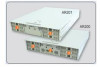
AR200 2U RAID Storage Subsystem User Guide - Asus AR201 | Manual for AR200 - Page 2
LIKE), EVEN IF ASUS HAS BEEN ADVISED OF THE POSSIBILITY OF SUCH DAMAGES ARISING FROM ANY DEFECT OR ERROR IN THIS MANUAL OR PRODUCT. Product warranty or service will not be extended if: (1) the product is repaired, modified or altered, unless such repair, modification of alteration is authorized in - Asus AR201 | Manual for AR200 - Page 3
Contents Disclaimer/Copyrights ii Contents iii Notices iv Safety information v About this guide vi ASUS contact information vii AR200 specifications summary viii Chapter 1: Product introduction 1-1 1.1 Package contents 1-2 1.1.1 Standard items 1-2 1.1.2 Optional items 1-2 1.2 System - Asus AR201 | Manual for AR200 - Page 4
. This equipment generates, uses and can radiate radio frequency energy and, if not installed and used in accordance with manufacturer's instructions, may cause harmful interference to radio communications. However, there is no guarantee that interference will not occur in a particular installation - Asus AR201 | Manual for AR200 - Page 5
supply is broken, do not try to fix it by yourself. Contact a qualified service technician or your dealer. CAUTION This product is equipped with a three-wire power engineers. • Before operating the server, carefully read all the manuals included with the server package. • Before using the server, - Asus AR201 | Manual for AR200 - Page 6
users with at least basic knowledge on RAID configuration. Contents This guide contains the following parts: 1. Chapter 1: System overview This chapter tasks properly, take note of the following symbols used throughout this manual. WARNING: Information to prevent injury to yourself when trying to - Asus AR201 | Manual for AR200 - Page 7
MB/Others (Tel): +886-2-2890-7121 (English) Notebook (Tel): +886-2-2890-7122 (English) Desktop/Server (Tel): +886-2-2890-7123 (English) Support Fax: +886-2-2890-7698 Web Site: www.asus.com.tw ASUS COMPUTER INTERNATIONAL (America) Address: 44370 Nobel Drive, Fremont, CA 94538, USA General - Asus AR201 | Manual for AR200 - Page 8
JBOD IBM PowerPC 6031 RISC CPU Ultra160 SCSI 4 SCSI channels (each channel supports 15 SCSI devices) 6 devices (each logical drive can implement a different RAID interface for RAID management Background reconstruction (automatic or manual selection) Automatic bad sector re-assignment Automatic drive - Asus AR201 | Manual for AR200 - Page 9
Product introduction Chapter 1 This chapter describes the general features of the AR200 RAID system. It includes sections on front panel, rear panel, and internal features of the system. ASUS AR200 RAID system 1-1 - Asus AR201 | Manual for AR200 - Page 10
(19") 280W redundant Internal SCSI, management LVD/SE Active Terminator (2 pcs.) DA3100 128MB registered ECC SDRAM R-20 rackmount rail kit AR200 User Guide DA3100 Hardware Manual 1.1.2 Optional items • Hard disk drives Up to six SCA-2 Ultra160 SCSI If any of the above items is damaged or missing - Asus AR201 | Manual for AR200 - Page 11
hard disk configurations to provide more than 365GB storage capacity while keeping optimal fault tolerance and performance. The system supports RAID 0, 1, 3, 5, 0+1, and JBOD protocols, and comes with a comprehensive LCD panel information for easy configuration. 1.2.1 Front panel features Hard disk - Asus AR201 | Manual for AR200 - Page 12
the preinstalled components of the RAID system. Refer to "Chapter 2 Hardware Setup" for instructions on removing and installing the top cover of the chassis. Rear panel 10 1 2 encounter any problems with the system, contact ASUS technical support. See page vii of this user guide for ASUS contact - Asus AR201 | Manual for AR200 - Page 13
have individual LEDs. When a hard drive is installed, the specific LED for that hard drive is ON (steady green) under normal conditions. If there is a problem, the LED may turn to a steady amber. These LEDs are unlit when there is no hard drive is present. Hard disk activity LED This LED - Asus AR201 | Manual for AR200 - Page 14
the RAID controller, refer to the DA3100 Hardware Manual that came with your system package. 8 1 an error message appears, or when service is required (e.g. when a drive problems with the controller, or if you wish to upgrade the memory, contact ASUS technical support. See page vii of this user guide - Asus AR201 | Manual for AR200 - Page 15
Chapter 2 This chapter describes the internal hardware components and provides the procedures for installing and removing hard disk drives. The SCSI cable connections is also described and illustrated in this chapter. Hardware setup ASUS AR200 RAID system 2-1 - Asus AR201 | Manual for AR200 - Page 16
2.1 Removing the chassis cover The AR200 chassis is a 2U form factor designed for easy assembly and disassembly, making the installation of internal components very convenient. At the top of the chassis is a rotating lock that secures the cover to the chassis. Unlocking the Cover To unlock the cover - Asus AR201 | Manual for AR200 - Page 17
2.2 Installing SCSI hard disk drives The RAID system comes with six externally accessible hard disk drive bays. Hot-Swap Drive Tray On each of the HDD bays is a hotswap tray for mounting a hard disk drive. Flip open the tray levers to release the tray, then slide the tray out of the chassis. Tray - Asus AR201 | Manual for AR200 - Page 18
2.3 Cooling system The chassis includes an 8-cm system fan located at the front end of the PCI cage, and a 12-cm system blower (underneath a metal hood) located between the PCI cage and the power supply. The metal hood is held in place by two tabs (one on each side) that rest on the edge of the PCI - Asus AR201 | Manual for AR200 - Page 19
2.4 SCSI backplane boards The system includes two SCSI backplane boards to support up to six Ultra160 SCA SCSI hard disk drives. The backplane design incorporates a hot-swap feature to allow easy connection or removal of SCSI hard - Asus AR201 | Manual for AR200 - Page 20
2.5 System interface board The system interface board interconnects the backplane boards, power supply, cooling fans, and the DA3100 controller. Refer to the illustration below for the specific cables connected to the interface board. All the cables are already connected when you receive the system. - Asus AR201 | Manual for AR200 - Page 21
2.6 DA3100 connectors Inside the DA3100 RAID controller are connectors that connect to other system components using interface and power cables. Refer to the illustration below for the specific cable connections. All the cables are already connected when you receive the system. You do not need to - Asus AR201 | Manual for AR200 - Page 22
2.7 Power supply 2.7.1 Power cable connections The AR200 power supply unit (PSU) consists of two redundant power supply modules with five power plugs. The picture below indicates where you need to connect the PSU power plugs. P2 SMBus connector on left backplane board P3 Left backplane board P5 - Asus AR201 | Manual for AR200 - Page 23
2.8 System connections 2.8.1 SCSI cabling for cluster system (MSCS) 2.8.2 Standalone system ASUS AR200 RAID system 2-9 - Asus AR201 | Manual for AR200 - Page 24
2.8.3 Storage sub-system Refer to the following diagram to connect AR200 with AR201 (storage cabinet) when creating a storage sub-system. 2-10 Chapter 2: Hardware setup
-
 1
1 -
 2
2 -
 3
3 -
 4
4 -
 5
5 -
 6
6 -
 7
7 -
8
-
9
-
10
-
11
-
12
-
13
-
14
-
15
-
16
-
17
-
18
-
19
-
20
-
21
-
22
-
23
-
24
 |
 |

2U RAID Storage Subsystem
AR200
User Guide