Asus AT3GC-I User Manual
Asus AT3GC-I - Motherboard - Mini ITX Manual
 |
UPC - 610839171613
View all Asus AT3GC-I manuals
Add to My Manuals
Save this manual to your list of manuals |
Asus AT3GC-I manual content summary:
- Asus AT3GC-I | User Manual - Page 1
AT3GC-I Motherboard - Asus AT3GC-I | User Manual - Page 2
purposes, without the express written permission of ASUSTeK Computer Inc. ("ASUS"). Product warranty or service will not be extended if: (1) the AS A COMMITMENT BY ASUS. ASUS ASSUMES NO RESPONSIBILITY OR LIABILITY FOR ANY ERRORS OR INACCURACIES THAT MAY APPEAR IN THIS MANUAL, INCLUDING THE PRODUCTS - Asus AT3GC-I | User Manual - Page 3
About this guide vi AT3GC-I specifications summary viii Chapter 1: Product introduction 1.1 Before you proceed 1-1 1.2 Motherboard overview 1-2 1.2.1 Motherboard layout 1-2 1.2.2 Layout contents 1-2 1.3 Central Processing Unit (CPU 1-3 1.4 System memory 1-3 1.4.1 Overview 1-3 1.4.2 Memory - Asus AT3GC-I | User Manual - Page 4
CPU Configuration 2-8 2.4.3 Chipset 2-8 2.4.4 Onboard Devices Configuration 2-9 2.4.5 PCI PnP 2-10 2.5 Power menu 2-10 2.5.1 Suspend Mode 2-11 2.5.2 ACPI 2.0 Support 2-11 2.5.3 ACPI APIC Support [Enabled 2-11 2.5.4 APM Configuration 2-11 2.5.5 HW Monitor Configuration 2-12 2.6 Boot menu - Asus AT3GC-I | User Manual - Page 5
undesired operation. This equipment has been tested and found to comply with the accordance with manufacturer's instructions, may cause harmful to the graphics card is required to assure compliance with FCC ASUS REACH website at http://green.asus.com/english/REACH.htm DO NOT throw the motherboard - Asus AT3GC-I | User Manual - Page 6
are using, contact your local power company. • If the power supply is broken, do not try to fix it by yourself. Contact a qualified service technician or your retailer. Operation safety • Before installing the motherboard and adding devices on it, carefully read all the manuals that came with the - Asus AT3GC-I | User Manual - Page 7
manual. DANGER/WARNING: Information to prevent injury to yourself when trying to complete a task. CAUTION: Information to prevent damage to the components when trying to complete a task. IMPORTANT: Instructions ASUS websites The ASUS website provides updated information on ASUS - Asus AT3GC-I | User Manual - Page 8
non-ECC DDR2 533 MHz memory module Supports up to 2GB system memory Graphics Expansion slots Storage Audio USB LAN ASUS special features Back panel I/O ports * Refer to www.asus.com for the latest Memory QVL (Qualified Vendors List). Integrated Intel Graphics Media Accelerator 950 D-Sub - Asus AT3GC-I | User Manual - Page 9
12V power connector 1 x TPM connector (optional) 8Mb Flash ROM, AMI BIOS, PnP, DMI2.0, WfM2.0, SM BIOS 2.5, ACPI2.0a 1 x Serial ATA cable 1 x UltraDMA 100/66 cable 1 x I/O shield 1 x User's Manual Drivers ASUS Update ASUS PC Probe II Anti-Virus software (OEM version) User Manual MiniITX form factor - Asus AT3GC-I | User Manual - Page 10
Chapter 1 Product introduction Thank you for buying an ASUS® AT3GC-I motherboard! Before you start installing the motherboard, and hardware devices on it, check the items in your motherboard package. Refer to page ix for the list of accessories. If any of the items is damaged or missing, contact - Asus AT3GC-I | User Manual - Page 11
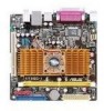
can damage the motherboard. 1.2.2 Layout contents Connectors/Jumpers/Slots/LED 1. Keyboard power (3-pin KBPWR) 2. Chassis fan connectors (3-pin CHA_FAN) 3. ATX power connectors (24-pin EATXPWR, 4-pin ATX12V) 4. USB device wake-up (3-pin USBPW1-4, USBPW5-8) 5. Intel® Atom processor 330 and heatsink - Asus AT3GC-I | User Manual - Page 12
an onboard Intel® Atom 330 processor and a specially designed CPU heatsink. 1.4 System memory 1.4.1 Overview The motherboard comes with one Double Data Rate 2 (DDR2) Dual Inline Memory Modules (DIMM) sockets. The figure illustrates the location of the DDR2 DIMM socket: AT3GC-I DIMM1 AT3GC-I 240 - Asus AT3GC-I | User Manual - Page 13
they support. Unplug the power cord before adding or removing expansion cards. Failure to do so may cause you physical injury and damage motherboard slot The PCI slots support cards such as LAN cards, SCSI cards, USB cards, and other cards that comply with the PCI specifications. ASUS AT3GC-I 1-4 - Asus AT3GC-I | User Manual - Page 14
clear the CMOS memory of date, time, and system setup parameters by erasing the CMOS RTC RAM data. The onboard button cell battery powers the RAM data overclocking. For system failure due to overclocking, use the CPU Parameter Recall (C.P.R.) feature. Shut down and reboot the system, then the BIOS - Asus AT3GC-I | User Manual - Page 15
(the default is the Space Bar)s. This feature requires an ATX power supply that can supply at least 1A on the +5VSB lead, and a corresponding setting in the BIOS. KBPWR 12 23 +5V +5VSB (Default) AT3GC-I AT3GC-I Keyboard Power Setting 3. USB device wake-up (3-pin USBPW1-4, USBPW5-8) Set these - Asus AT3GC-I | User Manual - Page 16
Linked BLINKING Data activity SPEED LED Status Description OFF 10 Mbps connection ORANGE 100 Mbps connection GREEN 1 Gbps connection ACT/LINK SPEED LED LED LAN port 4. Line In port (light blue). This port connects to the tape, CD, DVD player, or other audio sources. 5. Line Out port (lime - Asus AT3GC-I | User Manual - Page 17
RSATA_RXN2 GND SATA1 GND RSATA_TXP1 RSATA_TXN1 GND RSATA_RXP1 RSATA_RXN1 GND AT3GC-I SATA connectors Install the Windows® XP Service Pack 2 or later version before using Serial ATA. CD Left Audio Channel GND GND Right Audio Channel AT3GC-I Internal audio connector AT3GC-I AT3GC-I ASUS AT3GC-I 1-8 - Asus AT3GC-I | User Manual - Page 18
100/66 signal cable: blue, black, and gray. Connect the blue connector to the motherboard's IDE connector, then select one of the following modes to configure your devices. Single for Ultra DMA 100/66 IDE devices. PRI_IDE AT3GC-I PIN1 NOTE:Orient the red markings on the IDE ribbon cable to PIN - Asus AT3GC-I | User Manual - Page 19
chassis. These USB connectors comply with the USB 2.0 specification that supports up to 480Mbps connection speed. USB56 PIN 1 USB+5V motherboard components. It is not a jumper! DO NOT place jumper cap on the fan connector. CHA_FAN GND +12V Rotation AT3GC-I fan connectors AT3GC-I ASUS AT3GC - Asus AT3GC-I | User Manual - Page 20
become unstable or may not boot up if the power is inadequate. • If you are uncertain about the minimum power supply requirement for your system, refer to the Recommended Power Supply Wattage Calculator at http://support.asus. com/PowerSupplyCalculator/PSCalculator.aspx?SLanguage=en-us for details - Asus AT3GC-I | User Manual - Page 21
mode depending on the BIOS settings. Pressing the power switch for more than four seconds while the system is ON turns the system OFF. • Reset button (2-pin RESET) This 2-pin connector is for the chassis-mounted reset button for system reboot without turning off the system power. ASUS AT3GC-I 1-12 - Asus AT3GC-I | User Manual - Page 22
HD-audio-compliant Legacy AC'97 pin definition compliant definition AT3GC-I Analog front panel connector If you want to connect a high-definition front panel audio module to this connector, ensure that the Front Panel Support Type item in the BIOS is set to [HD Audio]. If you want to connect - Asus AT3GC-I | User Manual - Page 23
you install Windows® XP Service Pack 2 or later versions / Windows® Vista Service Pack 1 or later versions before installing the drivers for better compatibility and system stability. 1.8.2 Support DVD information The Support DVD that comes with the motherboard package contains drivers, software - Asus AT3GC-I | User Manual - Page 24
, save, and update the motherboard BIOS in Windows® environment. • ASUS Update requires an Internet connection either through a network or an Internet Service Provider (ISP). • This utility is available in the Support DVD that comes with the motherboard package. Installing ASUS Update: 1. Place the - Asus AT3GC-I | User Manual - Page 25
BIOS file from the Open window, then click Open. 3. Follow the onscreen instructions to complete the updating process. 2.1.2 ASUS EZ Flash 2 utility The ASUS EZ Flash 2 feature allows you to update the BIOS ASUSTek EZ Flash 2 BIOS ROM Utility V3.37 FLASH TYPE: MXIC 25L8005 Current ROM BOARD: AT3GC - Asus AT3GC-I | User Manual - Page 26
size should be smaller than 8GB. • DO NOT shut down or reset the system while updating the BIOS! Doing so can cause system boot failure! The recovered BIOS may not be the latest BIOS version for this motherboard. Download the latest BIOS file from the ASUS website at www.asus.com. 2-3 ASUS AT3GC-I - Asus AT3GC-I | User Manual - Page 27
at www.asus.com to download the latest BIOS file for this motherboard. 2.3 Main menu When you enter the BIOS Setup program, the Main menu screen appears, giving you an overview of the basic system information. Main Advanced Power BIOS SETUP UTILITY Boot Tools Exit Main Settings System - Asus AT3GC-I | User Manual - Page 28
then press to display the IDE device information. The BIOS automatically detects the values opposite the dimmed items (Device, Vendor, mode. Setting to [Auto] enables the LBA mode if the device supports this mode, and if the device was not previously formatted with [ARMD] 2-5 ASUS AT3GC-I - Asus AT3GC-I | User Manual - Page 29
such as Windows® XP/Vista. Configuration options: [Disabled] [Compatible Mode] [Enhanced Mode] Enhanced Mode Support On [S-ATA] BIOS automatically detects the items in this menu. AMI BIOS Displays the auto-detected BIOS information Processor Displays the auto-detected CPU specification System Memory - Asus AT3GC-I | User Manual - Page 30
malfunction. Main Advanced Power BIOS SETUP UTILITY Boot ] [Disabled] Legacy USB Support [Auto] Allows you to enable or disable support for Legacy USB storage devices BIOS waits for the USB storage device to initialize. Configuration options: [10 Sec] [20 Sec] [30 Sec] [40 Sec] 2-7 ASUS AT3GC-I - Asus AT3GC-I | User Manual - Page 31
CPU-related information that the BIOS automatically detects. Max CPUID Value boot even without support for CPUs with or disable the Intel® Hyper Threading ). When disabled, you can manually set the DRAM timing parameters to enabled to reduce bottlenecks of memory bandwidth. Sets it to disabled for - Asus AT3GC-I | User Manual - Page 32
supports. Configuration options: [AC97] [HD Audio] Onboard PCIEX LAN [Enabled] Allows you to enable or disable the onboard PCIe 10/100 MB LAN controller. Configuration options: [Enabled] [Disabled] LAN ] [DMA1] [DMA3] Parallel Port IRQ [IRQ7] Configuration options: [IRQ5] [IRQ7] 2-9 ASUS AT3GC-I - Asus AT3GC-I | User Manual - Page 33
Power Management (APM). Select an item then press to display the configuration options. Power Settings Suspend Mode ACPI 2.0 Support ACPI APIC Support APM Configuration HW Monitor Configuration [Auto] [Disabled] [Enabled] Select the ACPI state used for System Suspend. Chapter 2: BIOS - Asus AT3GC-I | User Manual - Page 34
power on. Power On By PCI Devices [Disabled] When set to [Enabled], this parameter allows you to wake the system through a PCI LAN or modem card. This feature requires an ATX power supply that provides at least 1A on the +5VSB lead. Configuration options: [Disabled] [Enabled] 2-11 ASUS AT3GC - Asus AT3GC-I | User Manual - Page 35
wake the system through a LAN connection. Configuration options: [Disabled] [Enabled] Power On By PS/2 Keyboard [Disabled] Allows you to use specific keys on the keyboard to turn on the system. This feature requires an ATX power supply to the motherboard, the field Power Boot Device Priority BIOS - Asus AT3GC-I | User Manual - Page 36
Disabled] 2.6.2 Boot Settings Configuration Quick Boot [Enabled] Enabling this item allows the BIOS to skip some power on self tests (POST) while booting to decrease the time needed to boot the system. When Password Installed appears after you successfully set your password. 2-13 ASUS AT3GC-I - Asus AT3GC-I | User Manual - Page 37
. To clear the supervisor password, select the Change Supervisor Password then press twice. The message Password uninstalled appears. If you forget your BIOS password, you can clear it by erasing the CMOS Real Time Clock (RTC) RAM. See section 1.6 Jumpers for information on how to erase - Asus AT3GC-I | User Manual - Page 38
menu Main Advanced Tools Settings ASUS EZ Flash 2 Power BIOS SETUP UTILITY Boot Tools Exit AI NET2 Press ENTER to run the utility to select and update BIOS. This utility supports : 1. FAT 12/16/32 (r/w) 2. NTFS (read only) 2.7.1 ASUS EZ Flash 2 Allows you to run ASUS EZ Flash 2. When you press
-
 1
1 -
 2
2 -
 3
3 -
 4
4 -
 5
5 -
 6
6 -
 7
7 -
8
-
9
-
10
-
11
-
12
-
13
-
14
-
15
-
16
-
17
-
18
-
19
-
20
-
21
-
22
-
23
-
24
-
25
-
26
-
27
-
28
-
29
-
30
-
31
-
32
-
33
-
34
-
35
-
36
-
37
-
38
 |
 |

Motherboard
AT3GC-I