Asus C8HM70-I C8HM70-I User's Manual
Asus C8HM70-I Manual
 |
View all Asus C8HM70-I manuals
Add to My Manuals
Save this manual to your list of manuals |
Asus C8HM70-I manual content summary:
- Asus C8HM70-I | C8HM70-I User's Manual - Page 1
Motherboard C8HM70-I SERIES • C8HM70-I • C8HM70-I/HDMI - Asus C8HM70-I | C8HM70-I User's Manual - Page 2
by ASUS; or (2) the serial number of the product is defaced or missing. ASUS PROVIDES THIS MANUAL " (1) for free by downloading it from http://support.asus.com/download or (2) for the cost of reproduction Software licenses. If however you encounter any problems in obtaining the full corresponding source code - Asus C8HM70-I | C8HM70-I User's Manual - Page 3
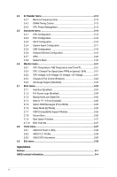
Installing an operating system 1-15 1.8.2 Support DVD information 1-15 BIOS information 2.1 Managing and updating your BIOS 2-1 2.1.1 ASUS Update utility 2-1 2.1.2 ASUS EZ Flash 2 2-2 2.1.3 ASUS CrashFree BIOS 3 utility 2-3 2.1.4 ASUS BIOS Updater 2-4 2.2 BIOS setup program 2-6 2.3 Main menu - Asus C8HM70-I | C8HM70-I User's Manual - Page 4
Monitor menu 2-21 2.6.1 CPU Temperature / MB Temperature [xxxºC/xxxºF 2-21 2.6.2 CPU / Chassis Fan Speed [xxxx RPM] or [Ignore] / [N/A 2-21 2.6.3 CPU Voltage, 3.3V Voltage, 5V Voltage, 12V Voltage 2-21 2.6.4 Chassis Q-Fan Control [Enabled 2-22 2.6.5 Anti Surge Support [Disabled 2-22 2.7 Boot - Asus C8HM70-I | C8HM70-I User's Manual - Page 5
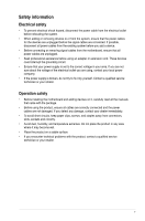
are using, contact your local power company. • If the power supply is broken, do not try to fix it by yourself. Contact a qualified service technician or your retailer. Operation safety • Before installing the motherboard and adding devices on it, carefully read all the manuals that came with the - Asus C8HM70-I | C8HM70-I User's Manual - Page 6
need when installing and configuring the motherboard. How this guide is organized This guide contains the following parts: • Chapter 1: Product introduction This chapter describes the features of the motherboard and the new technology it supports. • Chapter 2: BIOS information This chapter tells how - Asus C8HM70-I | C8HM70-I User's Manual - Page 7
, take note of the following symbols used throughout this manual. DANGER/WARNING: Information to prevent injury to yourself when completing a task. CAUTION: Information to prevent damage to the components when completing a task IMPORTANT: Instructions that you MUST follow to complete a task. . NOTE - Asus C8HM70-I | C8HM70-I User's Manual - Page 8
® Celeron® 847 (BGA1023) Intel® HM70 chipset 2 x SODIMM, max. 16GB, DDR3 1333/1066 MHz, non-ECC, un-buffered memory Dual-channel memory architecture • Refer to www.asus.com or the user manual for Memory QVL (Qualify Vendor List) Integrated Graphics Processor- Intel® HD Graphics support - Supports - Asus C8HM70-I | C8HM70-I User's Manual - Page 9
C8HM70-I SERIES specifications summary BIOS features Support DVD Form factor 64 Mb Flash ROM, UEFI AMI BIOS, PnP, DMI2.0, WfM2.0,SM BIOS 2.7, ACPI 2.0a, Multi-language BIOS, ASUS EZ Flash 2, ASUS CrashFree BIOS 3 Drivers ASUS utilities ASUS Update Anti-virus software (OEM version) Mini ITX Form - Asus C8HM70-I | C8HM70-I User's Manual - Page 10
887 Intel® HM70 64Mb BIOS SATA6G_1 SATA3G_1 EATXPWR Lithium Cell CMOS Power USB1112 CLRTC F_PANEL C8HM70-I/HDMI SPEAKER CHASSIS PCIEX16_1 SB_PWR ASUS C8HM70-I/HDMI motherboard User Manual 1 x Serial ATA 3.0 Gb/s cable 1 x Serial ATA 6.0 Gb/s cable 1 x I/O-Shield User Guide Support - Asus C8HM70-I | C8HM70-I User's Manual - Page 11
that you should shut down the system and unplug the power cable before removing or plugging in any motherboard component. The illustration below shows the location of the onboard LED. SB_PWR C8HM70-I/HDMI ON OFF Standby Power Powered Off C8HM70-I/HDMI Onboard LED ASUS C8HM70-I Series 1-1 - Asus C8HM70-I | C8HM70-I User's Manual - Page 12
the power cord before installing or removing the motherboard. Failure to do so can cause you physical injury and damage motherboard components. C8HM70-I Series motherboards include C8HM70-I and C8HM70-I/HDMI models. The package contents vary from models. The layout illustrations in this user guide - Asus C8HM70-I | C8HM70-I User's Manual - Page 13
Cell CMOS Power CLRTC C8HM70-I/HDMI PCIEX16_1 F_PANEL SPEAKER CHASSIS SB_PWR 11 10 9 8 7 6 Following Intel's specification, USB 2.0 ports 5 ~ 8 are disabled on the motherboards with Intel® HM70 chipset. 1.2.4 Layout contents Connectors/Jumpers/Slots/LED 1. CPU and chassis fan connectors - Asus C8HM70-I | C8HM70-I User's Manual - Page 14
1.3 Central Processing Unit (CPU) The motherboard comes with an onboard Intel® Celeron™ 847 (BGA1023) processor and a specially designed CPU heatsink. Intel® Celeron847 C8HM70-I/HDMI C8HM70-I/HDMI CPU Celeron847 1.4 System memory 1.4.1 Overview This motherboard comes with two Double Data Rate 3 ( - Asus C8HM70-I | C8HM70-I User's Manual - Page 15
C8HM70-I Series Motherboard Qualified Vendors Lists (QVL) DDR3-1333 Double-sided DIMM support: • A*: Supports one module inserted into either slot. • B*: Supports one pair of modules inserted into both the slots. Visit the ASUS website at www.asus.com for the latest QVL. ASUS C8HM70-I Series 1-5 - Asus C8HM70-I | C8HM70-I User's Manual - Page 16
, if any. See Chapter 2 for information on BIOS setup. 2. Assign an IRQ to the card. 3. Install the software drivers for the expansion card. 1.5.3 PCI Express x16 slot This motherboard has a PCI Express 2.0 x16 slot (at 16x mode) that supports PCI Express 2.0 x16 graphic cards complying with the - Asus C8HM70-I | C8HM70-I User's Manual - Page 17
. • You do not need to clear the RTC when the system hangs due to overclocking. For system failure due to overclocking, use the CPU Parameter Recall (C.P.R.) feature. Shut down and reboot the system, then the BIOS automatically resets parameter settings to default values. ASUS C8HM70-I Series 1-7 - Asus C8HM70-I | C8HM70-I User's Manual - Page 18
1.7 1.7.1 1 Connectors Rear panel connectors 2 34 10 9 8 7 6 5 1. PS/2 Keyboard / Mouse Combo port. This port is for a PS/2 keyboard or PS/2 mouse. 2. LAN (RJ-45) port. This port allows Gigabit connection to a Local Area Network (LAN) through a network hub. Refer to the table below for - Asus C8HM70-I | C8HM70-I User's Manual - Page 19
panel to support an 8-channel audio output. 6. USB 2.0 ports 3 and 4. These two 4-pin Universal Serial Bus (USB) ports are for USB 2.0/1.1 devices. 7. Video Graphics Adapter (VGA) port. This 15-pin port is for a VGA monitor or other VGA-compatible devices 8. HDMI port (C8HM70-I/HDMI only). This - Asus C8HM70-I | C8HM70-I User's Manual - Page 20
AC'97 pin definition compliant definition C8HM70-I/HDMI Front panel audio connector • We recommend that you connect a high-definition front panel audio module to this connector to avail of the motherboard's high-definition audio capability. • If you want to connect a high-definition front panel - Asus C8HM70-I | C8HM70-I User's Manual - Page 21
Volts C8HM70-I/HDMI ATX power connectors • For a fully configured system, we recommend that you use a power supply power is inadequate. • If you are uncertain about the minimum power supply requirement for your system, refer to the Recommended Power Supply Wattage Calculator at http://support.asus - Asus C8HM70-I | C8HM70-I User's Manual - Page 22
pin CHA_FAN) Connect the fan cables to the fan connectors on the motherboard, ensuring that the black wire of each cable matches the ground pin of the connector. CHA_FAN GND CHA FAN PWR CHA FAN IN CHA FAN PWM C8HM70-I/HDMI CPU_FAN GND +12V Rotation C8HM70-I/HDMI CPU fan connector Do not forget - Asus C8HM70-I | C8HM70-I User's Manual - Page 23
HDMI C8HM70-I/HDMI SATA 6.0Gb/s connector • You must install Windows® XP Service Pack 3 or later version before using Serial ATA hard disk drives. • When using hot-plug and NCQ, set the SATA Mode Selection item in the BIOS to [AHCI]. See section 2.5.3 SATA Configuration for details. GND RSATA_TXP1 - Asus C8HM70-I | C8HM70-I User's Manual - Page 24
connector (10-1 pin PANEL) This connector supports several chassis-mounted functions. F_PANEL PWR LED PWR BTN PLED+ PLEDPWR GND PIN 1 HD_LED+ HD_LED- Ground HWRST# (NC) C8HM70-I/HDMI +HD_LED RESET C8HM70-I/HDMI System panel connector • System power LED (2-pin PWRLED) This 2-pin connector - Asus C8HM70-I | C8HM70-I User's Manual - Page 25
at www.asus.com for updates. To run the Support DVD Place the Support DVD into the optical drive. If Autorun is enabled in your computer, the DVD automatically displays the Specials screen which contains the unique features of ASUS motherboard. Click Drivers, Utilities, Make Disk, Manual, and - Asus C8HM70-I | C8HM70-I User's Manual - Page 26
1-16 Chapter 1: Product introduction - Asus C8HM70-I | C8HM70-I User's Manual - Page 27
update the motherboard BIOS in Windows® environment. • ASUS Update requires an Internet connection either through a network or an Internet Service Provider (ISP). • This utility is available in the support DVD that comes with the motherboard package. Installing ASUS Update To install ASUS Update - Asus C8HM70-I | C8HM70-I User's Manual - Page 28
to avail all its features. Updating from a BIOS file a. Select Update BIOS from file, then click Next. b. Locate the BIOS file from the Open window, then click Open. 3. Follow the onscreen instructions to complete the updating process. 2.1.2 ASUS EZ Flash 2 The ASUS EZ Flash 2 feature allows you - Asus C8HM70-I | C8HM70-I User's Manual - Page 29
file using the motherboard support DVD or a USB flash drive that contains the updated BIOS file. • Before using this utility, rename the BIOS file in the removable device to C8HM70I.CAP for the C8HM70-I model and HM70IH.CAP for the C8HM70-I/HDMI model. • The BIOS file in the support DVD may not be - Asus C8HM70-I | C8HM70-I User's Manual - Page 30
screen displays may not be same as shown. Before updating BIOS 1. Prepare the motherboard support DVD and a USB flash drive in FAT32/16 format and single partition. 2. Download the latest BIOS file and BIOS Updater from the ASUS website at http://support.asus.com and save them on the USB flash drive - Asus C8HM70-I | C8HM70-I User's Manual - Page 31
Updating the BIOS file To update the BIOS file using BIOS Updater: 1. At the FreeDOS prompt, type bupdater /pc /g and press . 2. The BIOS Updater screen appears as below. ASUSTek BIOS Updater for DOS V1.30 Current ROM BOARD: C8HM70-I/HDMI VER: 0202 DATE: 08/29/2012 Update ROM BOARD: - Asus C8HM70-I | C8HM70-I User's Manual - Page 32
Use the BIOS Setup program to update the BIOS or configure its parameters. The BIOS screens include navigation keys and brief online help to guide you in using the BIOS Setup program. Entering BIOS Setup at startup To enter BIOS Setup at startup: • Press during the Power-On Self Test (POST - Asus C8HM70-I | C8HM70-I User's Manual - Page 33
for details. Displays the CPU/motherboard temperature, CPU/5V/3.3V/12V voltage output, CPU/chassis fan speed Selects the display language of the BIOS setup program Exits the BIOS setup program without saving the only when the boot device is installed to the system. ASUS C8HM70-I Series 2-7 - Asus C8HM70-I | C8HM70-I User's Manual - Page 34
Boot Tool Exit For changing the basic system configuration For changing the overclocking settings For changing the advanced system settings For displaying the system temperature, power status, and changing the fan settings For changing the system boot configuration For configuring options for - Asus C8HM70-I | C8HM70-I User's Manual - Page 35
item and press . Pop-up window Select a menu item and press to display a pop-up window with the configuration options for that item. corner of the menu screen are the navigation keys for the BIOS setup program. Use the navigation keys to select items in . ASUS C8HM70-I Series 2-9 - Asus C8HM70-I | C8HM70-I User's Manual - Page 36
information, and allows you to set the system date, time, language, and security settings. 2.3.1 System Language [English] Allows you to choose the BIOS language version from the options. Configuration options: [English] [Français] [Español] [Deutsch 2.3.2 System Date [Day xx/xx/xxxx] Allows you - Asus C8HM70-I | C8HM70-I User's Manual - Page 37
accessing the system. Otherwise, you might be able to see or change only selected fields in the BIOS setup program. To set an administrator password: 1. Select the Administrator Password item and press . User Password item on top of the screen shows Not Installed. ASUS C8HM70-I Series 2-11 - Asus C8HM70-I | C8HM70-I User's Manual - Page 38
configure overclocking-related items. Be cautious when changing the settings of the Ai Tweaker menu items. Incorrect field values can cause the system to malfunction. Target CPU Speed : 1100MHz Displays the target CPU speed. Target DRAM Speed : xxxxMHz Displays the target DRAM speed. 2.4.1 Memory - Asus C8HM70-I | C8HM70-I User's Manual - Page 39
the Enhanced Intel® SpeedStep Technology (EIST). [Disabled] Disables this function. [Enabled] The operating system dynamically adjusts the processor voltage and core frequency which may result in decreased average consumption and decreased average heat production. ASUS C8HM70-I Series 2-13 - Asus C8HM70-I | C8HM70-I User's Manual - Page 40
that the BIOS automatically detects. Intel Adaptive Thermal Monitor [Enabled] [Enabled] Enables the overheated CPU to throttle its clock speed to cool down. [Disabled] Disables the CPU thermal monitor function. Active Processor Cores [All] Allows you to choose the number of CPU cores to - Asus C8HM70-I | C8HM70-I User's Manual - Page 41
controls the CPU speed. CPU C1E [Auto] Allows you to enable or disable the CPU C1E. [Auto] Set this item automatically. [Disabled] Disables this function. [Enabled] Enables the C1E support function. This item should be enabled in order to enable the Enhanced Halt State. ASUS C8HM70-I Series - Asus C8HM70-I | C8HM70-I User's Manual - Page 42
CPU C7 report to OS. [Disabled] Disables this function. [Enabled] Enables the C7 report function. This item should be enabled in order to enable the Enhanced Halt State. Package C State Support entering Setup, the BIOS automatically detects the IDE] when you want to use the Serial ATA - Asus C8HM70-I | C8HM70-I User's Manual - Page 43
to select the amount of system memory allocated to DVMT 5.0 used by the iGPU. Configuration options: [Auto] [32M] [64M] [96M] [128M] ~ [480M] [512M] [1024M] Render Standby [Enabled] Allows you to enable the Intel® Graphics Render Standby support to reduce the iGPU power use when idle. Configuration - Asus C8HM70-I | C8HM70-I User's Manual - Page 44
.0 EHCI Controller [Enabled] [Disabled] Disables the Intel USB2.0 EHCI controller. [Enabled] Enables the Intel USB2.0 EHCI controller. Legacy USB Support [Enabled] [Disabled] The USB devices can be used only for the BIOS setup program. [Enabled] Enables the support for USB devices on legacy - Asus C8HM70-I | C8HM70-I User's Manual - Page 45
legacy AC'97 or highdefinition audio depending on the audio standard that the front panel audio module supports. [HD] Sets the front panel audio connector (AAFP) mode to high definition audio. [AC97 the Realtek LAN controller. Configuration options: [Enabled] [Disabled] ASUS C8HM70-I Series 2-19 - Asus C8HM70-I | C8HM70-I User's Manual - Page 46
the system state was before the AC power loss. Power On By PS/2 Keyboard [Disabled] [Disabled] Disables the Power On by a PS/2 keyboard. [Space Support [Enabled] This item allows user to disable or enable the Ipv4 PXE Boot support. Configuration options: [Disabled] [Enabled] Ipv6 PXE Support - Asus C8HM70-I | C8HM70-I User's Manual - Page 47
menu The Monitor menu displays the system temperature/power status, and allows you to change the fan settings. 2.6.1 CPU Temperature / MB Temperature [xxxºC/xxxºF] The onboard hardware monitor automatically detects and displays the CPU and motherboard temperatures. Select Ignore if you do not wish - Asus C8HM70-I | C8HM70-I User's Manual - Page 48
. [Turbo] Sets to [Turbo] to achieve maximum Chassis fan speed. [Manual] Sets to [Manual] to assign detailed fan speed control parameters. The following four items appear only when you set Chassis Fan Profile to [Manual]. Chassis Upper Temperature [70] Use the and keys to adjust - Asus C8HM70-I | C8HM70-I User's Manual - Page 49
2.7 Boot menu The Boot menu items allow you to change the system boot options. Scroll down to display the following items: ASUS C8HM70-I Series 2-23 - Asus C8HM70-I | C8HM70-I User's Manual - Page 50
only after entering the operating system (OS). Network Stack Driver Support [Disabled] [Disabled] Disables network stack driver support during POST. [Enabled] Enables network stack driver support during POST. Next boot after AC Power Loss [Normal Boot] [Normal Boot] Returns to normal boot - Asus C8HM70-I | C8HM70-I User's Manual - Page 51
entering the BIOS setup program. 2.7.7 CSM (Compatibility Support Module) This option allows you to control the CSM (Compatibility Support Module) driver first] [Ignore] Boot from PCIe Expansion Devices [Legacy OpR...] Configuration option: [Legacy OpROM first] [UEFI driver first] ASUS C8HM70-I - Asus C8HM70-I | C8HM70-I User's Manual - Page 52
Boot This option allows you to configure the Security Boot parameters. OS Type [Windows UEFI mode] Configuration option: [Windows UEFI mode] [Other OS] The following items appear when OS Type is set to [Windows UEFI mode]. Key Management Clear Secure Boot keys Configuration options: [Yes] [No] Load - Asus C8HM70-I | C8HM70-I User's Manual - Page 53
of device items that appears on the screen depends on the number of devices installed in the system. • To select the boot device during system startup, press when ASUS Logo appears. • To access Windows OS in Safe Mode, press after POST. Hard Drive BBS Priorities Allows you to set the - Asus C8HM70-I | C8HM70-I User's Manual - Page 54
the profile number that saved your CMOS settings, press , and then select Yes. • DO NOT shut down or reset the system while updating the BIOS to prevent the system boot failure! • We recommend that you update the BIOS file only coming from the same memory/ CPU configuration and BIOS version - Asus C8HM70-I | C8HM70-I User's Manual - Page 55
you to load the optimal default values for the BIOS items, and save or discard your changes to the BIOS items. You can access the EZ Mode from the option or if you press , a confirmation window appears. Select Yes to discard changes and exit. ASUS EZ Mode This option allows you to enter the EZ - Asus C8HM70-I | C8HM70-I User's Manual - Page 56
2-30 Chapter 2: Getting started - Asus C8HM70-I | C8HM70-I User's Manual - Page 57
cause undesired operation. This equipment has been tested and found to comply with the limits for in accordance with manufacturer's instructions, may cause harmful interference to . • Consult the dealer or an experienced radio/TV technician for help. The use of shielded cables C8HM70-I Series A-1 - Asus C8HM70-I | C8HM70-I User's Manual - Page 58
IC: Canadian Compliance Statement Complies with the Canadian ICES-003 Class B specifications. This device complies with RSS 210 of Industry Canada. This Class B device meets all the requirements of the Canadian interference-causing equipment regulations. This device complies with Industry Canada - Asus C8HM70-I | C8HM70-I User's Manual - Page 59
products at ASUS REACH website at http://csr.asus.com/english/REACH.htm. DO NOT throw the motherboard in municipal not be placed in municipal waste. ASUS Recycling/Takeback Services ASUS recycling and takeback programs come from asus.com/english/Takeback.htm for detailed recycling information - Asus C8HM70-I | C8HM70-I User's Manual - Page 60
CA 94539, USA Telephone +1-812-282-3777 Fax +1-510-608-4555 Web site usa.asus.com Technical Support Telephone Support fax Online support +1-812-282-2787 +1-812-284-0883 support.asus.com ASUS COMPUTER GmbH (Germany and Austria) Address Harkort Str. 21-23, D-40880 Ratingen, Germany - Asus C8HM70-I | C8HM70-I User's Manual - Page 61
Part 2 Section 2. 1077(a) Responsible Party Name: Asus Computer International Address: 800 Corporate Way, Fremont, CA 94539. Phone/Fax No: (510)739-3777/(510)608-4555 hereby declares that the product Product Name : Motherboard Model Number : C8HM70-I Conforms to the following specifications: FCC - Asus C8HM70-I | C8HM70-I User's Manual - Page 62
A-6 Appendices
-
 1
1 -
 2
2 -
 3
3 -
 4
4 -
 5
5 -
 6
6 -
 7
7 -
8
-
9
-
10
-
11
-
12
-
13
-
14
-
15
-
16
-
17
-
18
-
19
-
20
-
21
-
22
-
23
-
24
-
25
-
26
-
27
-
28
-
29
-
30
-
31
-
32
-
33
-
34
-
35
-
36
-
37
-
38
-
39
-
40
-
41
-
42
-
43
-
44
-
45
-
46
-
47
-
48
-
49
-
50
-
51
-
52
-
53
-
54
-
55
-
56
-
57
-
58
-
59
-
60
-
61
-
62
 |
 |

Motherboard
C8HM70-I SERIES
•
C8HM70-I
•
C8HM70-I/HDMI