Asus NCLV-DA User Guide
Asus NCLV-DA Manual
 |
View all Asus NCLV-DA manuals
Add to My Manuals
Save this manual to your list of manuals |
Asus NCLV-DA manual content summary:
- Asus NCLV-DA | User Guide - Page 1
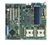
Motherboard NCLV-D Series - Asus NCLV-DA | User Guide - Page 2
Product warranty or service will not be extended if: (1) the product is repaired, modified or altered, unless such repair, modification of alteration is authorized in writing by ASUS; or (2) the serial number of the product is defaced or missing. ASUS PROVIDES THIS MANUAL "AS IS" WITHOUT WARRANTY - Asus NCLV-DA | User Guide - Page 3
used in this guide ix Typography ix NCLV-D Series Series specifications ASUS features 1-4 Chapter 2: Hardware information 2.1 Before you proceed 2-1 2.2 Motherboard overview 2-2 2.2.1 Placement direction 2-2 2.2.2 Screw holes 2-2 2.2.3 CPU heatsink weight support 2-3 2.2.4 Motherboard - Asus NCLV-DA | User Guide - Page 4
function power switch 3-2 Chapter 4: BIOS setup 4.1 Managing and updating your BIOS 4-1 4.1.1 Creating a bootable floppy disk 4-1 4.1.2 AFUDOS utility 4-2 4.1.3 ASUS CrashFree BIOS 2 utility 4-5 4.1.4 ASUS Update utility 4-7 4.2 BIOS setup program 4-10 4.2.1 BIOS menu screen 4-11 4.2.2 Menu - Asus NCLV-DA | User Guide - Page 5
ACPI APIC Support [Enabled 4-26 4.5.2 APM Configuration 4-27 4.5.3 Hardware Monitor 4-29 4.6 Boot menu 4-31 4.6.1 Boot Device Priority 4-31 4.6.2 Hard Disk Drives 4-31 4.6.3 Boot Settings Configuration 4-32 4.6.4 Security 4-33 4.7 Exit menu 4-36 Appendix: Block Diagram A.1 NCLV-D Series - Asus NCLV-DA | User Guide - Page 6
. This equipment generates, uses and can radiate radio frequency energy and, if not installed and used in accordance with manufacturer's instructions, may cause harmful interference to radio communications. However, there is no guarantee that interference will not occur in a particular installation - Asus NCLV-DA | User Guide - Page 7
Contact a qualified service technician or your retailer. Operation safety • Before installing the motherboard and adding devices on it, carefully read all the manuals that came with . • If you encounter technical problems with the product, contact a qualified service technician or your retailer. vii - Asus NCLV-DA | User Guide - Page 8
you need when installing and configuring the motherboard. How this guide is organized This manual contains the following parts: • Chapter 1: Product introduction This chapter describes the features of the motherboard and the new technology it supports. • Chapter 2: Hardware information This chapter - Asus NCLV-DA | User Guide - Page 9
following symbols used throughout this manual. D A N G E R / W A R N I N G : Information to prevent injury to yourself when trying to complete a task. C A U T I O N : Information to prevent damage to the components when trying to complete a task. I M P O R T A N T : Instructions that you MUST follow - Asus NCLV-DA | User Guide - Page 10
Mini-PCI socket for the ASUS Server Management Board NCLV-DA/NCLV-DS supports: 1 x PCI-X 66 MHz/64-bit slot (supports ZCR, PCI-X 1.0) Intel® 6300ESB South Bridge supports: - 2 x Ultra DMA supports: - 4 USB 2.0 ports (2 on the rear panel, 2 on the front panel) ASUS Smart Fan ASUS CrashFree BIOS 2 ASUS - Asus NCLV-DA | User Guide - Page 11
BIOS, 8 MB Flash ROM, Green, PnP, DMI2.0a, SMBIOS 2.3, WfM2.0 1 x PS/2 keyboard port (purple) 1 x PS/2 mouse port (green) 1 x Serial port 2 x LAN (RJ-45) port 2 x USB 2.0 ports 1 x Serial (COM2) port Floppy disk drive connector IDE connector Serial ATA connectors Serial ATA RAID connectors (NCLV-DA - Asus NCLV-DA | User Guide - Page 12
xii - Asus NCLV-DA | User Guide - Page 13
This chapter describes the motherboard features and the new technologies it supports. 1Product introduction - Asus NCLV-DA | User Guide - Page 14
Chapter summary 1 1.1 Welcome 1-1 1.2 Package contents 1-1 1.3 Special features 1-2 ASUS NCLV-D Series - Asus NCLV-DA | User Guide - Page 15
signal cables Serial ATA power cables (dual-plug) SCSI cable 3-in-1 disk drive cable CEK spring CPU X-PAD kit I/O shield ASUS motherboard support CD (includes ASWM) User guide NCLV-D Series -D -DA -DS 2 6 2 - - 2 2 2 If any of the above items is damaged or missing, contact your retailer - Asus NCLV-DA | User Guide - Page 16
with lower pin count, reduced voltage requirement, and up to 150 MB/s data transfer rate for 6300 ESB and 300 MB/s for AIC-8130. See page 2-31 and 2-30 for details. PCI Express™ interface The motherboard fully supports PCI Express, the latest I/O interconnect technology that speeds up the PCI bus - Asus NCLV-DA | User Guide - Page 17
on SATA models only) The Adaptec AIC-8130 PCI-X SATA-II controller also supports an optional Zero-Channel RAID card on the 64-bit PCI-X slot to create performance and added reliability. USB 2.0 technology The motherboard implements the Universal Serial Bus (USB) 2.0 ASUS NCLV-D Series 1-3 - Asus NCLV-DA | User Guide - Page 18
BIOS data from the support CD in case when the BIOS codes and data are corrupted. This protection eliminates the need to buy a replacement ROM chip. See page 4-5 for details. ASUS Smart Fan technology The ASUS 29 for details. ASUS MyLogo2™ This new feature present in the motherboard allows you to - Asus NCLV-DA | User Guide - Page 19
This chapter lists the hardware setup procedures that you have to perform when installing system components. It includes description of the jumpers and connectors on the motherboard. 2 Hardware information - Asus NCLV-DA | User Guide - Page 20
Chapter summary 2 2.1 Before you proceed 2-1 2.2 Motherboard overview 2-2 2.3 Central Processing Unit (CPU 2-10 2.4 System memory 2-14 2.5 Expansion slots 2-16 2.6 Jumpers 2-19 2.7 Connectors 2-25 ASUS NCLV-D Series - Asus NCLV-DA | User Guide - Page 21
motherboard components or change any motherboard so may cause severe damage to the motherboard, peripherals, and/or components. Onboard LED The motherboard comes with a standby power LED. motherboard component. The illustration below shows the location of the onboard LED. SB_PWR1 NCLV(Series) Onboard - Asus NCLV-DA | User Guide - Page 22
in the image below. 2.2.2 Screw holes Place nine (9) screws into the holes indicated by circles to secure the motherboard to the chassis. Do not overtighten the screws! Doing so can damage the motherboard. NCLV Place this side towards the rear of the chassis 2-2 Chapter 2: Hardware information - Asus NCLV-DA | User Guide - Page 23
two solutions to protect the motherboard. Using the X-PAD accessory kit To install the support plates: 1. Open and lay your system chassis flat on a stable surface, then place the motherboard standoffs on the holes as shown slightly lower than the standoffs on your chassis. ASUS NCLV-D Series 2-3 - Asus NCLV-DA | User Guide - Page 24
4. Use a plier to attach four nuts to the bolts on the metal support plate. 5. Align a rubber pad to the rectagular mark on the center of the plate, then press to attach. 6. Remove the adhesive label underneath a plate. 2-4 Chapter 2: Hardware information - Asus NCLV-DA | User Guide - Page 25
7. Carefully align and place the plate on a rectangular cut on the contour sheet. Make sure that the metal support plates fit perfectly to the rectangular cuts on the contour sheet; otherwise, the CPU heatsink screws would not align to the metal nuts. 8. Repeat steps 4 - Asus NCLV-DA | User Guide - Page 26
rear panel. The CPU sockets should be right on top of the support plates. Heatsink hole matched to a nut on the support plate Make sure that the CPU heatsink holes on the motherboard perfectly match the metal nuts on the support plates; otherwise, you can not install the CPU heatsinks properly. 11 - Asus NCLV-DA | User Guide - Page 27
Two CEK springs come with the motherboard package. You can also use these springs to support the weight of the CPU heatsinks. CEK spring: 1. Locate the CPU heatsink holes on the motherboard. 2. Position the CEK spring underneath the motherboard, then match the CEK spring hooks to the CPU1 heatsink - Asus NCLV-DA | User Guide - Page 28
holes until they snap in place. 5. Repeat the process to install the second spring to the CPU2 heatsink holes. The support plates appear as shown when installed. 6. Install the motherboard with the external I/O ports toward the chassis rear panel. The CPU sockets should be right on top of the CEK - Asus NCLV-DA | User Guide - Page 29
12in) 2.2.4 Motherboard layout mPGA 604 VGA NCLV-D model 26.8cm (10.5in) PS/2KBMS T: B: Mouse Keyboard KBPWR1 ATXPWR1 ATX12V1 USB12 REAR_FAN1 PSUSMB1 USBPW12 NCLV-D COM1 PCI4 (32-bit 5V PCI) Super I/O 8Mbit Flash BIOS CLRTC1 SB_PWR1 RECOVERY1 PCI5 (32-bit 5V PCI) CR2032 3V - Asus NCLV-DA | User Guide - Page 30
PS/2KBMS T: B: Mouse Keyboard KBPWR1 SSIPWR1 SSI12V1 USB12 REAR_FAN1 PSUSMB1 USBPW12 NCLV-DA COM1 DDR DDR_B2 (64 bit,184-pin module) DDR DDR_A2 (64 bit link) VGA_EN1 PCI4 (32-bit 5V PCI) Super I/O 8Mbit Flash BIOS CLRTC1 SB_PWR1 RECOVERY1 PCI5 (32-bit 5V PCI) CR2032 3V Lithium Cell - Asus NCLV-DA | User Guide - Page 31
) PS/2KBMS T: B: Mouse Keyboard KBPWR1 SSIPWR1 SSI12V1 USB12 REAR_FAN1 PSUSMB1 USBPW12 NCLV-DS COM1 DDR DDR_B2 (64 bit,184-pin module) DDR DDR_A2 (64 x4 link) VGA_EN1 PCI4 (32-bit 5V PCI) Super I/O 4Mbit Flash BIOS CLRTC1 SB_PWR1 RECOVERY1 PCI5 (32-bit 5V PCI) CR2032 3V Lithium Cell - Asus NCLV-DA | User Guide - Page 32
setting (3-pin LAN_EN2) 7. SATA controller setting (3-pin SATA_EN1) 8. 8130 LED setting (3-pin 8130LED1) 9. VGA Graphics controller setting (3-pin VGA-EN1) 10. BIOS Recovery setting (3-pin RECOVERY1) Page 2-23 2-24 2-24 2-25 2-25 2-26 2-26 2-27 2-27 2-28 Rear panel connectors 1. PS/2 mouse port - Asus NCLV-DA | User Guide - Page 33
2-pin IDE_LED) System warning speaker (Orange 4-pin SPEAKER) ATX power button/soft-off button (Yellow 2-pin PWRSW) Reset button (Blue 2-pin RESET) Page 2-30 2-30 2-31 2-32 2-34 2-34 2-35 2-35 2-36 2-37 2-37 2-38 2-38 2-39 2-39 2-39 2-39 2-39 2-39 2-39 2-39 2-40 2-40 2-40 2-40 2-40 2-40 - Asus NCLV-DA | User Guide - Page 34
cache. The new generation Xeon™ processor supports 800 MHz system bus and Extended Memory 64-bit Technology (EM64T). 2.3.1 Installling the CPU To install a CPU: 1. Locate the CPU sockets on the motherboard. CPU1 Intel Xeon CPU2 Gold Arrow Pin A1 NCLV(Series) CPU Socket 604 If installing only - Asus NCLV-DA | User Guide - Page 35
the CPU. This thermal grease should come with the CPU package. 7. Repeat steps 1 to 6 if you wish to install a second CPU. Marked corner (gold arrow) ASUS NCLV-D Series 2-15 - Asus NCLV-DA | User Guide - Page 36
to the top of the CPU before installing the heatsink and fan. • Refer to the installation manual that came with the CPU package for details on heatsink/fan assembly and installation. CPU heatsink (top on the heatsink align with the nuts on the support plate. 2-16 Chapter 2: Hardware information - Asus NCLV-DA | User Guide - Page 37
heatsink if you have installed a second CPU, then connect the fan cable to the 4-pin connector labeled CPU_FAN2. The heatsinks appear as shown when installed. ASUS NCLV-D Series 2-17 - Asus NCLV-DA | User Guide - Page 38
2.4 System memory 2.4.1 Overview The motherboard comes with four Double Data Rate (DDR) Dual Inline Memory Modules (DIMM) sockets that supports up to 16GB of system memory. A DDR module has the same physical dimensions as a DDR DIMM but has a 184-pin footprint. DDR DIMMs are notched - Asus NCLV-DA | User Guide - Page 39
or removing DIMMs or other system components. Failure to do so may cause severe damage to both the motherboard and the components. 1. Unlock a DIMM socket by pressing the retaining clips outward. 2. Align a DO NOT force a DIMM into a socket to avoid damaging the DIMM. ASUS NCLV-D Series 2-19 - Asus NCLV-DA | User Guide - Page 40
following sub-sections describe the slots and the expansion cards that they support. Make sure to unplug the power cord before adding or removing settings for the card. 2. Remove the system unit cover (if your motherboard is already installed in a chassis). 3. Remove the bracket opposite the slot - Asus NCLV-DA | User Guide - Page 41
BIOS setup. 2. Assign an IRQ to the card. Refer to the tables on the next page. 3. Install the software drivers for the expansion card. When using PCI cards on shared slots, ensure that the drivers support Compatible Mouse Port* Numeric Data Processor Primary IDE Channel Secondary IDE Channel * These - Asus NCLV-DA | User Guide - Page 42
for various server class high performance add-on cards like SCSI RAID card, fiber-channel card, etc. 2.5.5 PCI/PCI-X slots The PCI/PCI-X slots support cards such as a LAN card, SCSI card, USB card, and other cards that comply with PCI 2.3 and PCI-X 1.0 specifications. The figure shows a LAN card - Asus NCLV-DA | User Guide - Page 43
computer. 6. Hold down the key during the boot process and enter BIOS setup to re-enter data. Except when clearing the RTC RAM, never remove the cap on CLRTC jumper default and reboot the system so the BIOS can automatically reset parameter settings to default values. ASUS NCLV-D Series 2-23 - Asus NCLV-DA | User Guide - Page 44
FM_CPU1 12 23 DC mode (Default) PWM FM_CPU2 21 32 DC mode (Default) NCLV(Series) FM_CPU Setting PWM 3 . USB device wake-up (3-pin USBPW12, USBPW34) mode). USBPW12 12 23 +5V (Default) +5VSB USBPW34 12 23 +5V NCLV(Series) USB device wake-up (Default) +5VSB • The USB device wake- - Asus NCLV-DA | User Guide - Page 45
least 1A on the +5VSB lead, and a corresponding setting in the BIOS. KBPWR1 12 23 +5V (Default) +5VSB NCLV(Series) Keyboard power setting 5 . Gigabit LAN controller setting (3-pin LAN_EN1 . LAN_EN1 21 32 Enable (Default) Disable NCLV(Series) LAN_EN1 setting ASUS NCLV-D Series 2-25 - Asus NCLV-DA | User Guide - Page 46
onboard Broadcom BCM5705E Gigabit LAN controller. Set to pins 1-2 to activate the Gigabit LAN feature. LAN_EN2 2 1 Enable (Default) 3 2 Disable NCLV(Series) LAN_EN2 setting 7 . SATA controller setting (3-pin SATA_EN1) (Optional) These jumpers allow you to enable or disable the onboard Adaptec - Asus NCLV-DA | User Guide - Page 47
enable or disable the onboard 8130 LED. Set to pins 1-2 to enable the LED. NCLV(Series) 8130 LED setting 8130 LED1 12 23 Disable (Default) Enable 9 . VGA enable the video graphics controller. NCLV(Series) VGA Setting VGA_EN1 1 2 Enable (Default) 2 3 Disable ASUS NCLV-D Series 2-27 - Asus NCLV-DA | User Guide - Page 48
. 7.Replace the jumper cap from pins 2-3 to pins 1-2. 8.Reboot your computer. 9.Hold down the < D e l > key during the boot process and enter BIOS setup to re-enter data. RECOVERY1 1 2 Normal (Default) NCLV(Series) BIOS recovery setting 2 3 BIOS Recovery 2-28 Chapter 2: Hardware information - Asus NCLV-DA | User Guide - Page 49
for the LAN port LED indications. LAN port LED indications ACT/LINK LED SPEED LED Status Description Status Description0 OFF GREEN BLINKING No link Linked Data activity OFF ORANGE GREEN 10 Mbps connection 100 Mbps connection 1 Gbps connection ACT/LINK SPEED LED LED LAN port - Asus NCLV-DA | User Guide - Page 50
NOTE: Orient the red markings on the floppy ribbon cable to PIN 1. NCLV(Series) Floppy disk drive connector 2 . IDE connectors (40-1 pin PRI_IDE1 has three connectors: a blue connector for the primary IDE connector on the motherboard, a black connector for an Ultra DMA 100/66 IDE slave device ( - Asus NCLV-DA | User Guide - Page 51
n d a r d I D E mode, you can connect Serial ATA boot/data hard disk drives to these connectors. If you intend to create a Serial ATA RAID A s item in the BIOS to [RAID]. See section "4.3.5 IDE Configuration" on for details. NCLV-D NCLV-D SATA connectors SATA2 GND NCLV-DS model only) NCLV-DS NCLV - Asus NCLV-DA | User Guide - Page 52
Service Pack 4 or the Windows® XP Service Data support NCLV-DA DA model only. • Before creating a RAID set using Serial ATA hard disks, make sure that you have connected the Serial ATA signal cable and installed Serial ATA hard disk drives; ; otherwise, you cannot enter the RAID utility and SATA BIOS - Asus NCLV-DA | User Guide - Page 53
-pin Ultra160/320 SCSI connector supports a maximum of 15 devices as specified by the Ultra160/320 standards. NCLV-DS SCSI1 68-Pin Ultra320/ 1 35 Ultra2-Wide SCSI Connector 34 68 NCLV-DS Onboard SCSI connector • , the bus defaults to an SE speed and 1.5m cable length. ASUS NCLV-D Series 2-33 - Asus NCLV-DA | User Guide - Page 54
LED to light up. HDLED1 1 SCSI_ACTLED+ SCSI_ACTLEDSCSI_ACTLEDSCSI_ACTLED+ NCLV(Series) SCSI/SATA card activity LED connector 6 support cooling fans of 350 mA ~ 740 mA (8.88 W max.) or a total of 2.1 A ~ 4.44 A (53.28 W max.) at +12V. Connect the fan cables to the fan connectors on the motherboard - Asus NCLV-DA | User Guide - Page 55
with USB 2.0 specification that supports up to 480 Mbps connection speed. USB+5V USB_P6USB_P6+ GND NC USB+5V USB_P5USB_P5+ USB+5V USB34 NCLV(Series) USB 2.0 connector Never connect a 1 3 9 4 c a b l e to the USB connectors. Doing so will damage the motherboard! 8 . Serial port connector (10 - Asus NCLV-DA | User Guide - Page 56
+3 Volts Ground +5 Volts Ground +5 Volts Ground Power OK +5V Standby +12 Volts +12 Volts +3 Volts +12V CPU +12V CPU +12V CPU +12V CPU 1 NCLV(Series) Power connectors +3 Volts -12 Volts Ground PSON# Ground Ground Ground -5 Volts +5 Volts +5 Volts +5 Volts Ground For Power Supply with 20-pin Power - Asus NCLV-DA | User Guide - Page 57
SMBus host and/or other SMBus devices using the SMBus interface. BPSMB1 1 NCLV(Series) SMBus connector 11. Power Supply SMBus connector (5-pin PSUSMB1) This connector devices using the SMBus interface. PSUSMB1 NCLV(Series) Power supply SMBus connector PSU_I2CCLK PSU_I2CDATA NC GND +3.3V Remote Sense - Asus NCLV-DA | User Guide - Page 58
the module to a slot opening at the back of the system chassis. LPT1 Pin 1 NCLV(Series) Parallel port connector 13. BMC connector (16-pin BMCCONN1) This connector is for an ASUS server management card. BMCCONN1 NCLV(Series) BMC connector +5VSB +5VSB BMC SMBCLK 12CCLK1 PSON# BMC_RST# PWROK PSONEN - Asus NCLV-DA | User Guide - Page 59
14. System panel auxiliary connector (20-pin AUX_PANEL1) This connector supports several server system functions. NC I2C_4_CLK# GND I2C_4_DATA# +3V LAN1_LINKACTLED+ Devices communicate with an SMBus host and/or other SMBus devices using the SMBus interface. ASUS NCLV-D Series 2-39 - Asus NCLV-DA | User Guide - Page 60
supports several chassis-mounted functions. POWERLED+ GND POWERLEDMLED+ MLEDNC +5V GND GND SPKROUT HDLED+ HDLEDNMIBTN# GND POWERBTN# GND NC RESETBTN# GND PANEL1 NCLV LED lights up or flashes when data is read from or written to -off mode depending on the BIOS settings. Pressing the power switch - Asus NCLV-DA | User Guide - Page 61
This chapter describes the power up Powerin3g up sequence, the vocal POST messages, and ways of shutting down the system. - Asus NCLV-DA | User Guide - Page 62
Chapter summary 3 3.1 Starting up for the first time 3-1 3.2 Powering off the computer 3-2 ASUS NCLV-D Series - Asus NCLV-DA | User Guide - Page 63
then runs the power-on self tests or POST. While the tests are running, the BIOS beeps (see BIOS beep codes table below) or additional messages appear on the screen. If you do not on, hold down the key to enter the BIOS Setup. Follow the instructions in Chapter 4. ASUS NCLV-D Series 3-1 - Asus NCLV-DA | User Guide - Page 64
is ON, pressing the power switch for less than four seconds puts the system to sleep mode or to soft-off mode, depending on the BIOS setting. Pressing the power switch for more than four seconds lets the system enter the soft-off mode regardless of the - Asus NCLV-DA | User Guide - Page 65
This chapter tells how to change the system settings through the BIOS Setup menus. Detailed descriptions of the BIOS parameters are also provided. 4 BIOS setup - Asus NCLV-DA | User Guide - Page 66
Chapter summary 4 4.1 Managing and updating your BIOS 4-1 4.2 BIOS setup program 4-10 4.3 Main menu 4-13 4.4 Advanced menu 4-17 4.5 Power menu 4-26 4.6 Boot menu 4-31 4.7 Exit menu 4-36 ASUS NCLV-D Series - Asus NCLV-DA | User Guide - Page 67
BIOS using a bootable floppy disk or the motherboard support CD when the BIOS file fails or gets corrupted.) 3. A S U S U p d a t e (Updates the BIOS motherboard BIOS file to a bootable floppy disk in case you need to restore the BIOS in the future. Copy the original motherboard BIOS using the ASUS - Asus NCLV-DA | User Guide - Page 68
BIOS screens are for reference only. The actual BIOS screen displays may not be same as shown. 1. Copy the AFUDOS utility (afudos.exe) from the motherboard support CD copies the current BIOS file to the floppy disk. A:\>afudos /oOLDBIOS1.rom AMI Firmware Update Utility - Version 1.19(ASUS V2.07(03. - Asus NCLV-DA | User Guide - Page 69
(www.asus.com) and download the latest BIOS file for the motherboard. Save the BIOS file to a bootable floppy disk. Write the BIOS filename on a piece of paper. You need to type the exact BIOS filename at the DOS prompt. 2. Copy the AFUDOS utility (afudos.exe) from the motherboard support CD to - Asus NCLV-DA | User Guide - Page 70
A:\>afudos /iNCLV-D.ROM /pbnc AMI Firmware Update Utility - Version 1.19(ASUS V2.07(03.11.24BB)) Copyright (C) 2002 American Megatrends, Inc. All rights reserved. WARNING!! Do not turn off power during flash BIOS Reading file ....... done Reading flash ...... done Advance Check ...... Erasing flash - Asus NCLV-DA | User Guide - Page 71
2 utility The ASUS CrashFree BIOS 2 is an auto recovery tool that allows you to restore the BIOS file when it fails or gets corrupted during the updating process. You can update a corrupted BIOS file using the motherboard support CD or the floppy disk that contains the updated BIOS file. • Prepare - Asus NCLV-DA | User Guide - Page 72
disk drive, then turn on the system. 2. Insert the support CD to the optical drive. 3. The utility displays the following message and automatically checks the floppy disk for the original or updated BIOS file. Bad BIOS checksum. Starting BIOS recovery... Checking for floppy... When no floppy disk is - Asus NCLV-DA | User Guide - Page 73
, and • View the BIOS version information. This utility is available in the support CD that comes with the motherboard package. ASUS Update requires an Internet connection either through a network or an Internet Service Provider (ISP). Installing ASUS Update To install ASUS Update: 1. Place the - Asus NCLV-DA | User Guide - Page 74
the Internet To update the BIOS through the Internet: 1. Launch the ASUS Update utility from the Windows® desktop by clicking S t a r t > P r o g r a m s > A S U S > A S U S U p d a t e > A S U S U p d a t e. The ASUS Update main window appears. 2. Select U p d a t e B I O S f r o m 3. Select - Asus NCLV-DA | User Guide - Page 75
e. The ASUS Update main window appears. 2. Select U p d a t e B I O S f r o m a f i l e option from the drop-down menu, then click N e x t. 3. Locate the BIOS file from the O p e n window, then click S a v e. 4. Follow the screen instructions to complete the update process. ASUS NCLV-D Series 4-9 - Asus NCLV-DA | User Guide - Page 76
program This motherboard supports a programmable firmware chip that you can update using the provided utility described in section "4.1 Managing and updating your BIOS." Use the BIOS Setup program when you are installing a motherboard, reconfiguring your system, or prompted to "Run Setup". This - Asus NCLV-DA | User Guide - Page 77
4.2.1 BIOS menu screen Menu items Menu bar Configuration fields General help System Time System Date Legacy Diskette A Primary IDE Master Primary IDE keys to select items in the menu and change the settings. Some of the navigation keys differ from one screen to another. ASUS NCLV-D Series 4-11 - Asus NCLV-DA | User Guide - Page 78
IDE Configuration System Information [11:10:19] [Thu 03/27/2003] [1.44M, 3.5 in] [English] :[ST320413A] :[ASUS CD-S340] :[Not Detected] :[Not Detected] :[Not Detected] :[Not Detected] Main menu items Use [ENTER], [TAB] is a brief description of the selected item. 4-12 Chapter 4: BIOS setup - Asus NCLV-DA | User Guide - Page 79
screen appears, giving you an overview of the basic system information. Refer to section "4.2.1 BIOS menu screen" for information on the menu screen items and how to navigate through them. 360K, 5.25 in.] [1.2M , 5.25 in.] [720K , 3.5 in.] [1.44M, 3.5 in.] [2.88M, 3.5 in.] ASUS NCLV-D Series 4-13 - Asus NCLV-DA | User Guide - Page 80
DMA-2 Ultra DMA : Ultra DMA-5 SMART Monitoring: Supported Type [Auto] LBA/Large Mode [Auto] Block(Multi-sector Transfer) [Auto] PIO Mode [Auto] DMA Mode [Auto] SMART Monitoring [Auto] 32Bit Data Transfer [Disabled] The BIOS automatically detects the values opposite the dimmed items - Asus NCLV-DA | User Guide - Page 81
[Disabled] [Enabled] 32Bit Data Transfer [Disabled] Enables or disables 32-bit data transfer. Configuration options: [ wish to configure the item. IDE Configuration Onboard IDE Operate Mode Enhanced Mode Support On Configure S-ATA as RAID IDE Detect Time Out (Sec) [Enhanced ASUS NCLV-D Series 4-15 - Asus NCLV-DA | User Guide - Page 82
O n l y options are for advanced users only. If you set to any of these options and encountered problems, revert to the default setting P r i m a r y P - A T A + S - gives you an overview of the general system specifications. The BIOS automatically detects the items in this menu. AMIBIOS Version : - Asus NCLV-DA | User Guide - Page 83
Module Version - 2.23.2-9.4 USB Devices Enabled: None USB Function Legacy USB Support USB 2.0 Controller USB 2.0 Controller Mode [All USB Ports] [Auto] USB Function [Enabled] Allows you to enable or disable the USB function. Configuration options: [Disabled] [Enabled] ASUS NCLV-D Series 4-17 - Asus NCLV-DA | User Guide - Page 84
USB controller legacy mode is enabled. If no USB device is detected, the legacy USB support is disabled. Configuration options: [Disabled] [Enabled] [Auto] USB 2.0 Controller [Enabled] Allows select the multi-processor system revision. Configuration options: [1.1] [1.4] 4-18 Chapter 4: BIOS setup - Asus NCLV-DA | User Guide - Page 85
Port Mode Flow Control Redirection After BIOS POST [COM1] [115200 8,n,1] [None] [Always] Terminal Type VT-UTFB Combo Key Support [ANSI] [Disabled] Select Remote port mode. Configuration options: [115200 8,n,1] [57600 8,n,1] [38400 8,n,1] [19200 8,n,1] [09600 8,n,1] ASUS NCLV-D Series 4-19 - Asus NCLV-DA | User Guide - Page 86
BIOS Power-On Self-Test (POST). Some operating systems may not work when this item is set to Always. Configuration options: [Disabled] [Boot Loader] [Always] Terminal Type [ANSI] Allows you to select the target terminal type. Configuration options: [ANSI] [VT100] [VT-UTF8] VT-UTF8 Combo Key Support - Asus NCLV-DA | User Guide - Page 87
information that the BIOS automatically detects. Configure clock and the Front Side Bus frequency. The BIOS auto-detects the default value of this item. Use systems to boot even without support for CPUs with extended CPUID the BIOS automatically checks the CPU's capability to enable the C1E support. - Asus NCLV-DA | User Guide - Page 88
you to disable or set to auto the CPU Internal Thermal Control function. The default setting [Auto] allows the BIOS to automatically detect whether the CPU supports temperature control. Configuration options: [Auto] [Disabled] 4.4.5 Chipset The Chipset menu allows you to change the advanced chipset - Asus NCLV-DA | User Guide - Page 89
[3F8/IRQ4] [2F8/IRQ3] [378] [Normal] [IRQ7] Allows BIOS to Select Serial Port1 Base Addresses. Serial Port1 Address [3F8/IRQ4] Allows set to E P P. Configuration options: [1.9] [1.7] Parallel Port IRQ [IRQ7] Sets the Parallel port IRQ. Configuration options: [IRQ5] [IRQ7] ASUS NCLV-D Series 4-23 - Asus NCLV-DA | User Guide - Page 90
assigned to IRQ-14 assigned to [PCI Device] [PCI Device] [PCI Device] [PCI Device] [PCI Device] [PCI Device] [PCI Device] [PCI Device] NO: Lets the BIOS configue all the devices in the system. YES: Lets the operating system configure Plug and Play (PnP) devices not required for boot if your system - Asus NCLV-DA | User Guide - Page 91
PCI IDE BusMaster [Enabled] Allows BIOS to use PCI bus mastering when reading/writing to IDE devices. Configuration options: [Disabled] [Enabled] Offboard Memory Size [Disabled] Allows you to set the reserved memory size. Configuration options: [Disabled] [16k] [32k] [64k] ASUS NCLV-D Series 4-25 - Asus NCLV-DA | User Guide - Page 92
Support APM Configuration Hardware Monitor [Enabled] Select the ACPI state used for System Suspend. 4.5.1 ACPI APIC Support [Enabled] Allows you to enable or disable the Advanced Configuration and Power Interface (ACPI) support the ACPI APIC support after you have installed the operating system ( - Asus NCLV-DA | User Guide - Page 93
] Enable or disable APM. Power Management [Enabled] Allows you to enable or disable the motherboard Advance Power Management (APM) feature. Configuration options: [Enabled] [Disabled] Video Power Down the power button is pressed. Configuration options: [On/Off] [Suspend] ASUS NCLV-D Series 4-27 - Asus NCLV-DA | User Guide - Page 94
], the items RTC Alarm Date, RTC Alarm Hour, RTC Alarm Minute, and RTC Alarm Second appear with set values. Configuration options: [Disabled] [Enabled] 4-28 Chapter 4: BIOS setup - Asus NCLV-DA | User Guide - Page 95
is not connected to the motherboard, the field shows N/A. Smart Fan Control [Disabled] Allows you to enable or disable the ASUS Smart Fan feature that smartly [XXX] Allows you to set the CPU and system threshold temperature before the Smart Fan Control is disabled. ASUS NCLV-D Series 4-29 - Asus NCLV-DA | User Guide - Page 96
Voltage, 5V Voltage, 5VSB Voltage, VBAT Voltage, 12V Voltage The onboard hardware monitor automatically detects the voltage output through the onboard voltage regulators. 4-30 Chapter 4: BIOS setup - Asus NCLV-DA | User Guide - Page 97
Device 2nd Boot Device 3rd Boot Device 4th Boot Device [1st FLOPPY DRIVE] [PM-ST330620A] [PS-ASUS CD-S360] [MBA v7.5.12 Slot 0] Specifies the boot sequence from the available devices. A device available hard disk drives. Configuration options: [xxxxxx Drive] [Disabled] ASUS NCLV-D Series 4-31 - Asus NCLV-DA | User Guide - Page 98
feature. Configuration options: [Disabled] [Enabled] Set this item to [Enabled] to use the ASUS MyLogo2™ feature. Add On ROM Display Mode [Force BIOS] Sets the display mode for option ROM. Configuration options: [Force BIOS] [Keep Current] Bootup Num-Lock [On] Allows you to select the power-on state - Asus NCLV-DA | User Guide - Page 99
. The message "Password Installed" appears after you successfully set your password. To change the supervisor password, follow the same steps as in setting a user password. ASUS NCLV-D Series 4-33 - Asus NCLV-DA | User Guide - Page 100
To clear the supervisor password, select the Change Supervisor Password then press . The message "Password Uninstalled" appears. If you forget your BIOS password, you can clear clear it by erasing the CMOS Real Time Clock (RTC) RAM. See section "2.6 Jumpers" for information on how to erase - Asus NCLV-DA | User Guide - Page 101
[Always], BIOS checks for user password both when accessing Setup and booting the system. Configuration options: [Setup] [Always] Boot Sector Virus Protection [Disabled] Allows you to enable or disable the boot sector virus protection. Configuration options: [Disabled] [Enabled] ASUS NCLV-D Series - Asus NCLV-DA | User Guide - Page 102
the changes that you made to the Setup program. If you made changes to fields other than System Date, System Time, and Password, the BIOS asks for a confirmation before exiting. Discard Changes Allows you to discard the selections you made and restore the previously saved values. After selecting - Asus NCLV-DA | User Guide - Page 103
you press , a confirmation window appears. Select Y e s to load default values. Select E x i t & S a v e C h a n g e s or make other changes before saving the values to the non-volatile RAM. ASUS NCLV-D Series 4-37 - Asus NCLV-DA | User Guide - Page 104
4-38 Chapter 4: BIOS setup
-
 1
1 -
 2
2 -
 3
3 -
 4
4 -
 5
5 -
 6
6 -
 7
7 -
8
-
9
-
10
-
11
-
12
-
13
-
14
-
15
-
16
-
17
-
18
-
19
-
20
-
21
-
22
-
23
-
24
-
25
-
26
-
27
-
28
-
29
-
30
-
31
-
32
-
33
-
34
-
35
-
36
-
37
-
38
-
39
-
40
-
41
-
42
-
43
-
44
-
45
-
46
-
47
-
48
-
49
-
50
-
51
-
52
-
53
-
54
-
55
-
56
-
57
-
58
-
59
-
60
-
61
-
62
-
63
-
64
-
65
-
66
-
67
-
68
-
69
-
70
-
71
-
72
-
73
-
74
-
75
-
76
-
77
-
78
-
79
-
80
-
81
-
82
-
83
-
84
-
85
-
86
-
87
-
88
-
89
-
90
-
91
-
92
-
93
-
94
-
95
-
96
-
97
-
98
-
99
-
100
-
101
-
102
-
103
-
104
 |
 |

Motherboard
NCLV-D
Series