Asus P3B-F P3B-F User Manual
Asus P3B-F - Motherboard - ATX Manual
 |
View all Asus P3B-F manuals
Add to My Manuals
Save this manual to your list of manuals |
Asus P3B-F manual content summary:
- Asus P3B-F | P3B-F User Manual - Page 1
® P3B-F Pentium® III / II / CeleronTM Motherboard USER'S MANUAL - Asus P3B-F | P3B-F User Manual - Page 2
manual revision number. Manual updates are represented by the third digit in the manual revision number. For previous or updated manuals, BIOS, drivers, or product release information, contact ASUS at http://www.asus.com.tw or through any of the means indicated on the following page. SPECIFICATIONS - Asus P3B-F | P3B-F User Manual - Page 3
@asuscom.de (for marketing requests only) Technical Support Hotline: MB/Others: +49-2102-9599-0 Notebook: +49-2102-9599-10 Fax: +49-2102-9599-11 Support (Email): www.asuscom.de/de/support (for online support) WWW: www.asuscom.de FTP: ftp.asuscom.de/pub/ASUSCOM ASUS P3B-F User's Manual 3 - Asus P3B-F | P3B-F User Manual - Page 4
DMA Channels for ISA Cards 31 3.8 External Connectors 32 3.9 Power Connection Procedures 41 4. BIOS SETUP 42 4.1 Managing and Updating Your BIOS 42 4.1.1 Upon First Use of the Computer System 42 4.1.2 Updating BIOS Procedures (only when necessary) ...... 43 4 ASUS P3B-F User's Manual - Asus P3B-F | P3B-F User Manual - Page 5
Install ADOBE AcroBat Reader Vx.x 83 5.9 Uninstalling Programs 84 6. SOFTWARE REFERENCE 85 6.1 Intel LANDesk Client Manager 85 6.2 ASUS PC Probe 91 7. APPENDIX 97 7.1 UltraDMA/66 PCI Card 97 7.2 PCI-L101 Fast Ethernet Card 109 7.3 ASUS S370 Series CPU Card 111 ASUS P3B-F User's Manual 5 - Asus P3B-F | P3B-F User Manual - Page 6
instructions from the Code of set out in the Radio Interference Regulations of the Canadian Department of Communications. This Class B digital apparatus complies with Canadian ICES-003. Cet appareil numérique de la classe B est conforme à la norme NMB-003 du Canada. 6 ASUS P3B-F User's Manual - Asus P3B-F | P3B-F User Manual - Page 7
3.5" floppy drives (1) Bag of spare jumper caps (1) Support CD with drivers and utilities (1) This Motherboard User's Manual ASUS IrDA-compliant infrared module (optional) ASUS S370 Series CPU cards (optional) ASUS PCI-L101 Wake-On-LAN 10/100 ethernet card (optional) ASUS P3B-F User's Manual 7 - Asus P3B-F | P3B-F User Manual - Page 8
2. FEA TURES Specifications 2. FEATURES 2.1 The ASUS P3B-F Motherboard The ASUS P3B-F is carefully designed for the demanding PC user who wants advanced features processed by the fastest CPU. 2.1.1 Specifications • Multi-Speed: Supports Intel Pentium® III (450MHz and faster), Pentium® II (233MHz to - Asus P3B-F | P3B-F User Manual - Page 9
interface. • Onboard LED: The onboard LED will light up when there is standby power to the PCI bus. This acts as a reminder to the user to turn OFF the power before plugging and unplugging devices so as not to damage the motherboard, peripherals, and/or components. ASUS P3B-F User's Manual 9 - Asus P3B-F | P3B-F User Manual - Page 10
Master UltraDMA/33 IDE which can handle data transfers up to 33MB/s. • SDRAM Optimized Performance: Supports the new generation memory - Synchronous Dynamic Random Access Memory (SDRAM) which increases the data transfer rate to 800MB/s max using PC100-compliant SDRAM. 10 ASUS P3B-F User's Manual - Asus P3B-F | P3B-F User Manual - Page 11
processors, so monitoring is necessary to ensure proper system configuration and management. • Chassis Intrusion Detection: Supports chassis-intrusion monitoring through the ASUS ASIC. A chassis intrusion event is kept in memory on battery power for more protection. ASUS P3B-F User's Manual 11 - Asus P3B-F | P3B-F User Manual - Page 12
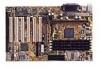
2. FEA TURES Specifications 2. FEATURES 2.2 Motherboard Parts 1 ATX Power Connector 2 Slot 1 CPU Socket 3 Intel 440BX AGPset 4 4 DIMM Sockets 5 IDE Connectors 6 ASUS ASIC with hardware monitor 7 Floppy Connectors 22 T: PS/2 Mouse Connector B: PS/2 Keyboard Connector 12 ASUS P3B-F User's Manual - Asus P3B-F | P3B-F User Manual - Page 13
2. FEATURES 12 3 4 5 22 21 20 19 18 2. FEA TURES Motherboard Parts 17 16 15 14 13 12 11 10 9 8 7 6 ASUS P3B-F User's Manual 13 - Asus P3B-F | P3B-F User Manual - Page 14
3.1 Motherboard Layout 440BX AGPset COM2 JTPWR Row 0 1 2 3 4 5 6 7 CR2032 3V Lithium Cell (CMOS Power) Accelerated Graphics Port PCI Slot 1 DIP Switches DSW R P3B-F Flash EEPROM (Programable BIOS ASUS ASIC with Hardware Monitor CHA_FAN PANEL JEN IDELED IR 14 ASUS P3B-F User's Manual - Asus P3B-F | P3B-F User Manual - Page 15
Setting (Enable/Disable) p. 20 I/O Voltage Setting (3.50/3.65 Volt) Expansion Slots/Sockets 1) System Memory p. 21 System Memory Support 2) DIMM0,1,2,3 p. 22 DIMM Memory Module Support 3) Slot 1 p. 23 CPU Support 20 pins) 23) JTPWR p. 38 Thermal Sensor Connector ASUS P3B-F User's Manual 15 - Asus P3B-F | P3B-F User Manual - Page 16
Motherboard Settings 2. Install Memory Modules 3. Install the Central Processing Unit (CPU) 4. Install Expansion Cards 5. Connect Ribbon Cables, Panel Wires, and Power Supply 6. Setup the BIOS Software 3.4 Motherboard Settings system. 3. H/W SETUP Motherboard Settings 16 ASUS P3B-F User's Manual - Asus P3B-F | P3B-F User Manual - Page 17
[OFF] (default) [ON] R P3B-F ON ON 1 2 3 4 5 6 7 8 9 10 1 2 3 4 5 6 7 8 9 10 DRAM Freq. x1 DRAM Freq. x2/3 P3B-F AGP Bus Frequency Setting WARNING! AGP bus frequencies above 66MHz exceed the specifications for the AGP interface and are not guaranteed to be stable. ASUS P3B-F User's Manual 17 - Asus P3B-F | P3B-F User Manual - Page 18
needed for the Pentium III / II / Celeron processor because it sends VID signals directly to the onboard power controller. WARNING! Frequencies above 100MHz exceed the specifications for the onboard Intel Chipset and are not guaranteed to be stable. 18 ASUS P3B-F User's Manual - Asus P3B-F | P3B-F User Manual - Page 19
7 8 9 10 8.0x(8/1) R P3B-F 3. H/W SETUP Motherboard Settings Manual CPU Settings NOTE: JumperFree mode must be disabled . Set the DIP switches by the Internal speed [ON] [ON] For updated processor settings, please visit ASUS' web site (see ASUS CONTACT INFORMATION). ASUS P3B-F User's Manual 19 - Asus P3B-F | P3B-F User Manual - Page 20
(default) [2-3] JP20 (VIO) 123 123 3.50 Volt (default) 3.65 Volt R P3B-F P3B-F Input/Output Voltage Setting WARNING! Using a higher voltage may help when overclocking but may result in the shortening of your computer components' life. Leave on default setting. 20 ASUS P3B-F User's Manual - Asus P3B-F | P3B-F User Manual - Page 21
supported: SDRAM with and without ECC. • SDRAM chips are generally thinner with higher pin density than EDO (Ex- tended Data Output) chips. • BIOS shows SDRAM memory on bootup screen. • Single-sided DIMMs come in 16, 32, 64,128MB; double-sided come in 32, 64, 128, 256MB. ASUS P3B-F User's Manual - Asus P3B-F | P3B-F User Manual - Page 22
have a higher pin density. Lock 88 Pins R P3B-F P3B-F 168-Pin DIMM Memory Sockets 60 Pins 20 Pins The DIMMs must be 3.3Volt motherboard. You must tell your retailer the correct DIMM type before purchasing. This motherboard supports four clock signals per DIMM. 22 ASUS P3B-F User's Manual - Asus P3B-F | P3B-F User Manual - Page 23
that the clamping design is different. 3.6.1 Universal Retention Mechanism Your motherboard comes preinstalled with a Universal Retention Mechanism (URM). The URM supports Pentium III / II and Celeron processors. 3. H/W SETUP CPU Universal Retention Mechanism (URM) ASUS P3B-F User's Manual 23 - Asus P3B-F | P3B-F User Manual - Page 24
folding support arms of the URM are locked when shipped. Locked Folding Support Arms To unlock the support arms, simply flip Unlocked Folding them up to an upright position. Support Arms 3. H/W SETUP CPU The URM is now ready for the installation of your processor. 24 ASUS P3B-F User's Manual - Asus P3B-F | P3B-F User Manual - Page 25
the CPU will overheat. Inspect visually to make sure that there is no gap between the processor die and the heatsink and that the heatsink is parallel to the processor. You may install an auxiliary fan to provide adequate circulation across the processor's passive heatsink. ASUS P3B-F User's Manual - Asus P3B-F | P3B-F User Manual - Page 26
motherboard's chipset, push the SECC2, SECC, or SEPP gently but firmly into the Slot 1 connector until it is fully inserted. SECC SECC2/SEPP Push lock inward CPU fan cable to fan connector CPU CPU fan cable to fan connector Lock hole CPU fan cable to fan connector 26 ASUS P3B-F User's Manual - Asus P3B-F | P3B-F User Manual - Page 27
Client Manager (LDCM) or the ASUS PC Probe software. SECC Heatsink & Fan SECC2 Heatsink & Fan NOTE: The SEPP heatsink and fan (for Intel Celeron processors) is similar to the SECC2 heatsink and fan except that the clamping design is different. 3. H/W SETUP CPU ASUS P3B-F User's Manual 27 - Asus P3B-F | P3B-F User Manual - Page 28
CPU temperature reported may be higher than those from motherboards that take readings from thermal sensors external to the processor. This is not a cause for alarm. If, however, the BIOS clip Example of an incorrectly installed retention clip 3. H/W SETUP CPU 28 ASUS P3B-F User's Manual - Asus P3B-F | P3B-F User Manual - Page 29
cause severe damage to both your motherboard and expansion cards. 3.7.1 Expansion Card Installation Procedure 1. Read the documentation for your expansion card and make any necessary hardware or software settings for your expansion card, such as jumpers. 2. Remove your computer system's cover and - Asus P3B-F | P3B-F User Manual - Page 30
to see all the interrupts and addresses for your system. Make sure that no two devices use the same IRQ or your computer will experience problems when those two devices are in use at the same time. 30 ASUS P3B-F User's Manual - Asus P3B-F | P3B-F User Manual - Page 31
(AGP) This motherboard provides an accelerated graphics port (AGP) slot to support a new generation of graphics cards with ultra-high memory bandwidth, such as an ASUS 3D Hardware Accelerator. R P3B-F 3. H/W SETUP DMA Channels P3B-F Accelerated Graphics Port (AGP) ASUS P3B-F User's Manual 31 - Asus P3B-F | P3B-F User Manual - Page 32
sources. These are clearly distinguished from jumpers in the motherboard layout. Placing jumper caps over these connectors will cause damage to your motherboard. IMPORTANT: Ribbon cables should always AT keyboards. 3. H/W SETUP Connectors PS/2 Keyboard (6-pin Female) 32 ASUS P3B-F User's Manual - Asus P3B-F | P3B-F User Manual - Page 33
Configuration. R P3B-F 3. H/W SETUP D CMoAnCnhecatnonrsels COM 1 COM 2 Serial Ports (9-pin Male) 5) Floppy Disk Drive Connector (34-1pin FLOPPY) This connector supports the provided red stripe to Pin 1 Floppy Drive Connector Pin 1 P3B-F Floppy Disk Drive Connector ASUS P3B-F User's Manual 33 - Asus P3B-F | P3B-F User Manual - Page 34
drive to Slave mode by setting its jumper accordingly. Refer to the documentation of your hard disk for the jumper settings. BIOS now supports specific device bootup (see Boot to PIN 1 PIN 1 P3B-F IDE Connectors R P3B-F Secondary IDE Connector Primary IDE Connector 34 ASUS P3B-F User's Manual - Asus P3B-F | P3B-F User Manual - Page 35
the motherboard and/or the CPU fan if these pins are incorrectly used. These are not jumpers, do not place jumper caps over these pins. Power Supply Fan CPU Fan Power Rotation +12V GND Rotation +12V GND R P3B-F Rotation +12V GND Chassis Fan Power P3B-F 12Volt Cooling Fan Power ASUS P3B-F User - Asus P3B-F | P3B-F User Manual - Page 36
Bus is a specific implementation of an I2C bus, which is a multi-master bus, that is, multiple chips can be connected to the same bus and each one can act as a master by initiating data transfer. R P3B-F SMBCLK Ground SMBDATA +5V P3B-F SMBus Connector 1 SMB 36 ASUS P3B-F User's Manual - Asus P3B-F | P3B-F User Manual - Page 37
through the internal modem card. NOTE: For external modems, WakeOn-Ring is detected through the COM port. IMPORTANT: This feature requires that PWR Up On Modem Act is set to Enabled (see 4.5.1 Power Up Control). WOR PIXRI# Ground 21 P3B-F Wake-On-Ring Connector R P3B-F ASUS P3B-F User's Manual 37 - Asus P3B-F | P3B-F User Manual - Page 38
is data received. This function requires an ACPI OS as well as application and driver support. 19) System Management Interrupt Lead (2-pin SMI) This allows the user to manually place the system into a suspend mode figure) connects to the case-mounted suspend switch. 38 ASUS P3B-F User's Manual - Asus P3B-F | P3B-F User Manual - Page 39
system between ON and SLEEP or ON and SOFT OFF, depending on your BIOS or OS setting. Pushing the switch while in the ON mode for more than 4 Ground R P3B-F Message LED SMI Lead P3B-F System Panel Connections Reset SW ATX Power Switch* 3. H/W SETUP Connectors ASUS P3B-F User's Manual 39 - Asus P3B-F | P3B-F User Manual - Page 40
powering on your system if your power supply cannot support the load. For Wake-OnLAN, keyboard wake up, and suspend-to-RAM support, your ATX power supply must supply at least Sensor Connector JTPWR 3. H/W SETUP Connectors R P3B-F P3B-F Thermal Sensor Connector 40 ASUS P3B-F User's Manual - Asus P3B-F | P3B-F User Manual - Page 41
on test. Check your jumper settings and connections again or call your retailer for assistance. 7. During power-on, hold down to enter BIOS setup. Follow the instructions in 4. BIOS SETUP. * Powering Off not appear when shutting down with ATX power supplies. ASUS P3B-F User's Manual 41 - Asus P3B-F | P3B-F User Manual - Page 42
AFLASH to run AFLASH. 4. BIOS SETUP Updating BIOS IMPORTANT! If "unknown" is displayed after Flash Memory:, the memory chip is either not programmable or is not supported by the ACPI BIOS and therefore, cannot be programmed by the Flash Memory Writer utility. 42 ASUS P3B-F User's Manual - Asus P3B-F | P3B-F User Manual - Page 43
2 and then press . The Update BIOS Including Boot Block and ESCD screen appears. 5. Type the filename of your new BIOS and the path, for example, A:\XXX- XX.XXX, and then press . NOTE: To cancel this operation, press . 4. BIOS SETUP Updating BIOS ASUS P3B-F User's Manual 43 - Asus P3B-F | P3B-F User Manual - Page 44
if the problem still persists, update the original BIOS file you saved to disk above. If the Flash Memory Writer utility was not able to successfully update a complete BIOS file, your system may not be able to boot up. If this happens, your system will need servicing. 44 ASUS P3B-F User's Manual - Asus P3B-F | P3B-F User Manual - Page 45
> key after the computer has run through its POST. NOTE: Because the BIOS software is constantly being updated, the following BIOS screens and descriptions are for reference purposes only and may not reflect your BIOS screens exactly. 4. BIOS SETUP Program Information ASUS P3B-F User's Manual 45 - Asus P3B-F | P3B-F User Manual - Page 46
Function Description or Displays the General Help screen from anywhere in the BIOS Setup Jumps to the Exit menu or returns to the main menu from a submenu to its Setup Defaults Saves changes and exits Setup 4. BIOS SETUP Menu Introduction 46 ASUS P3B-F User's Manual - Asus P3B-F | P3B-F User Manual - Page 47
appear in the Item Specific Help window located to the right of each menu. This window displays the help text for the currently highlighted field. NOTE: The item heading in square brackets represents the default setting for that field. 4. BIOS SETUP Menu Introduction ASUS P3B-F User's Manual 47 - Asus P3B-F | P3B-F User Manual - Page 48
3.5 in.] Floppy 3 Mode Support [Disabled] This is required to support older Japanese floppy drives. Floppy 3 Mode support will allow reading and writing of 1.2MB (as opposed to 1.44MB) on a 3.5-inch diskette. Configuration options: [Disabled] [Drive A] [Drive B] [Both] 48 ASUS P3B-F User's Manual - Asus P3B-F | P3B-F User Manual - Page 49
try updating your BIOS or enter the IDE hard disk drive parameters manually. NOTE: After the IDE hard disk drive information has been entered into BIOS, new set to active (also possible with FDISK). Other options for the Type field are: [None] - to disable IDE devices ASUS P3B-F User's Manual 49 - Asus P3B-F | P3B-F User Manual - Page 50
, you should enter the correct ones manually by setting [User Type HDD]. [User Type HDD] 4. BIOS SETUP Master/Slave Drives Manually enter the number of cylinders, heads and field must be set to [User Type HDD] and the Translation Method field must be set to [Manual]. 50 ASUS P3B-F User's Manual - Asus P3B-F | P3B-F User Manual - Page 51
data integrity for compatible IDE devices. Set to [Disabled] to suppress Ultra DMA capability. NOTE: To make changes to this field, the Type field must be set to [User Type HDD]. Configuration options: [0] [1] [2] [3] [4] [Disabled] 4. BIOS SETUP Master/Slave Drives ASUS P3B-F User's Manual 51 - Asus P3B-F | P3B-F User Manual - Page 52
password and a User password. When disabled, anyone may access all BIOS Setup program functions. When enabled, the Supervisor password is required for entering the BIOS Setup program and having full access to all Security menu options. 4. BIOS SETUP Main Menu 52 ASUS P3B-F User's Manual - Asus P3B-F | P3B-F User Manual - Page 53
Keyboard] [All but Disk] [All but Disk/Keyboard] Installed Memory [XXX MB] This field displays the amount of conventional memory detected by the system during bootup. You do not need to make changes to this field. This is a display only field. 4. BIOS SETUP Main Menu ASUS P3B-F User's Manual 53 - Asus P3B-F | P3B-F User Manual - Page 54
frequency) multiplied by the bus multiple equals the CPU's internal frequency (the CPU speed). CPU Vcore This field displays the core voltage supplied to the CPU. If you want to set it manually, always refer to the CPU documentation for the reasonable voltage range. 54 ASUS P3B-F User's Manual - Asus P3B-F | P3B-F User Manual - Page 55
OS/2 Onboard Memory > 64M [Disabled] When using OS/2 operating systems with installed DRAM of greater than 64MB, you need to set this option to [Enabled]; otherwise, leave this on [Disabled]. Configuration options: [Disabled] [Enabled] 4. BIOS SETUP Chip Configuration ASUS P3B-F User's Manual 55 - Asus P3B-F | P3B-F User Manual - Page 56
bus speed (66MHz). It will then automatically take you to the Advanced menu with a popup menu of all the officially possible CPU speeds. 4. BIOS SETUP Advanced Menu For processors with locked frequency multiplier For processors with unlocked frequency multiplier 56 ASUS P3B-F User's Manual - Asus P3B-F | P3B-F User Manual - Page 57
CPU settings, power OFF your system and restart. The system will start up in safe mode running at the slowest bus speed (66MHz) and enter BIOS setup. For processors with locked frequency multiplier 4. BIOS SETUP Chip Configuration For processors with unlocked frequency multiplier ASUS P3B-F User - Asus P3B-F | P3B-F User Manual - Page 58
controller waits to close a DRAM page after the CPU becomes idle. Leave on default setting. NOTE: To make changes to this field, the SDRAM Configuration field must be set to [User Define]. Configuration options: [0T] [2T] [4T] [8T] [10T] [12T] [16T] [32T] [Infinite] 58 ASUS P3B-F User's Manual - Asus P3B-F | P3B-F User Manual - Page 59
video memory of the processor. It can greatly improve the display speed by caching the display data. You must set this to UC (uncacheable) if your display card cannot support this . Configuration options: [Non-ECC] [EC-Only] [ECC] 4. BIOS SETUP Chip Configuration ASUS P3B-F User's Manual 59 - Asus P3B-F | P3B-F User Manual - Page 60
motherboard. If your system already has a second serial port connected to the onboard COM2 connector, it will no longer work if you enable the infrared feature. See IrDA-Compliant Infrared Module Connector in 3.8 External Connectors. Configuration options: [Disabled] [Enabled] 60 ASUS P3B-F User - Asus P3B-F | P3B-F User Manual - Page 61
IRQ7] [278H/IRQ5] Parallel Port Mode [ECP+EPP] This field allows you to set the operation mode of the parallel port. [Normal] allows normal-speed operation but in one in Parallel Port Mode above. Configuration options: [1] [3] [Disabled] 4. BIOS SETUP I/O Device Config ASUS P3B-F User's Manual 61 - Asus P3B-F | P3B-F User Manual - Page 62
will be disabled. [Disabled] will disable the motherboard's Symbios SCSI BIOS so that the BIOS on an external Symbios SCSI card can be used. If your Symbios SCSI card does not have a BIOS, the Symbios SCSI card will not function. Configuration options: [Auto] [Disabled] 62 ASUS P3B-F User's Manual - Asus P3B-F | P3B-F User Manual - Page 63
a legacy ISA card that requires a unique IRQ and you are not using an ICU, you must set the field for that IRQ to [Yes]. For example: If you install a legacy ISA card that requires IRQ 10, then set IRQ10 Used By ISA to [Yes]. Configuration options: [No/ICU] [Yes] ASUS P3B-F User's Manual 63 - Asus P3B-F | P3B-F User Manual - Page 64
that channel. If you install a legacy ISA card that requires a unique DMA channel, and you are not using an ICU, you must set the field for that channel to [Yes]. Configuration options: [No/ICU] [Yes] PCI/PNP ISA UMB Resource Exclusion 4. BIOS SETUP PCI Configuration 64 ASUS P3B-F User's Manual - Asus P3B-F | P3B-F User Manual - Page 65
other expansion cards with ROMs on them, you will need to know which addresses the ROMs use to shadow them specifically. Shadowing a ROM reduces the memory available between 640K and 1024K by the amount used for this purpose. Configuration options: [Disabled] [Enabled] ASUS P3B-F User's Manual 65 - Asus P3B-F | P3B-F User Manual - Page 66
you to set power saving options according to your preference. Configuration options: [User Define] [Disabled] [Min Saving] [Max Saving] IMPORTANT: Advanced Power Management (APM) should be installed to keep the system time updated when the computer enters suspend mode activated by the BIOS Power - Asus P3B-F | P3B-F User Manual - Page 67
4 seconds will place the system in sleep mode. Regardless of the setting, holding the ATX switch for more than 4 seconds will power off the system. NOTE: This field is only effective in APM OS system. Configuration options: [Soft off] [Suspend] 4. BIOS SETUP Power Menu ASUS P3B-F User's Manual 67 - Asus P3B-F | P3B-F User Manual - Page 68
Power Up Control 4. BIOS SETUP Power Up Control AC PWR Loss Restart [Disabled] This allows you to set whether you want your system to reboot after the power has been interrupted. [Disabled] Wake-OnLAN and an ATX power supply with at least 720mA +5V standby power. 68 ASUS P3B-F User's Manual - Asus P3B-F | P3B-F User Manual - Page 69
supply at least 300mA on the +5VSB lead. The default is set to [Disabled] because not all computers have the appropriate ATX power supply. Your computer will not by selecting [By Date]. Configuration options: [Disabled] [Everyday] [By Date] 4. BIOS SETUP Power Up Control ASUS P3B-F User's Manual 69 - Asus P3B-F | P3B-F User Manual - Page 70
. Set to [Ignore] only if necessary. NOTE: If any of the monitored items is out of range, an error message will appear: "Hardware Monitor found an error. Enter Power setup menu for details". You will then be prompted to "Press F1 to continue, DEL to enter SETUP". 70 ASUS P3B-F User's Manual - Asus P3B-F | P3B-F User Manual - Page 71
4.6 Boot Menu 4. BIOS SETUP Boot Menu Boot Sequence The Boot menu allows you to select among the four possible types of boot product IDs of all your connected ATAPI CD-ROM drives. Other Boot Device Select [Network] Configuration options: [Network] [SCSI Boot Device] ASUS P3B-F User's Manual 71 - Asus P3B-F | P3B-F User Manual - Page 72
-PnP OS is installed or you want to prevent reassigning of interrupt settings, select the default setting of [No]. Configuration options: [No] [Yes] Reset Configuration Data ] Full Screen Logo [Enabled] Configuration options: [Disabled] [Enabled] 4. BIOS SETUP Boot Menu 72 ASUS P3B-F User's Manual - Asus P3B-F | P3B-F User Manual - Page 73
. Select Exit from the menu bar to display the following menu: 4. BIOS SETUP Exit Menu NOTE: Pressing does not exit this menu. You to ensure the values you selected are saved to the CMOS RAM. The CMOS RAM is sustained by an onboard backup battery and stays on even ASUS P3B-F User's Manual 73 - Asus P3B-F | P3B-F User Manual - Page 74
select Exit Saving Changes or make other changes before saving the values to the non-volatile RAM. Discard Changes This option allows you to discard the selections you made and restore the [Yes] to save any changes to the non-volatile RAM. 4. BIOS SETUP Exit Menu 74 ASUS P3B-F User's Manual - Asus P3B-F | P3B-F User Manual - Page 75
in order to use the hardware manager features. • Install ASUS PC Probe Vx.xx: Installs a simple utility to monitor your computer's fan, temperature, and voltages. • Install ASUS Update Vx.xx: Installs a program to help you update your BIOS or download a BIOS image file. ASUS P3B-F User's Manual 75 - Asus P3B-F | P3B-F User Manual - Page 76
user's manuals saved in PDF format. Updated or other language versions of this motherboard's manual is available in PDF format at any of our web sites. • Show Motherboard Information: Allows you to view information about your motherboard, such as product name, BIOS version, and CPU. • Browse Support - Asus P3B-F | P3B-F User Manual - Page 77
5. SOFTWARE SETUP 5.3 Intel LDCM Administrator Setup Insert the Support CD that came with your motherboard into your CD-ROM drive or double-click the CD here. (4) Click here. 5. S/W SETUP Windows 98 (5) Click here. (6) Click here and then click Finish to restart. ASUS P3B-F User's Manual 77 - Asus P3B-F | P3B-F User Manual - Page 78
5. SOFTWARE SETUP 5.4 Intel LDCM Client Setup Insert the Support CD that came with your motherboard into your CD-ROM drive or double-click the CD drive icon . (2) Click here. (3) Click here. (4) Click here. 5. S/W SETUP Windows 98 (5) Click here. (6) Click here. 78 ASUS P3B-F User's Manual - Asus P3B-F | P3B-F User Manual - Page 79
5. SOFTWARE SETUP (7) Click here. (8) Click here. (9) Click here. (10) Click here. (11) Click here and then click Finish to restart. 5. S/W SETUP Windows 98 ASUS P3B-F User's Manual 79 - Asus P3B-F | P3B-F User Manual - Page 80
ASUS PC Probe Vx.xx Insert the Support CD that came with your motherboard into your CD-ROM drive or double-click the CD drive icon in My Computer to bring up the setup screen. NOTE: ASUS Click here. (8) Click Next and when the Setup Complete box appears, click Finish. 80 ASUS P3B-F User's Manual - Asus P3B-F | P3B-F User Manual - Page 81
ASUS Update Vx.xx Insert the Support CD that came with your motherboard into your CD-ROM drive or double-click the CD drive icon in My Computer to bring up the setup screen. (1) Click here. (2) Click here. (3) Click here. (4) Click here. (5) Click here. 5. S/W SETUP Windows 98 ASUS P3B-F User - Asus P3B-F | P3B-F User Manual - Page 82
5. SOFTWARE SETUP 5.7 Install PC-Cillin 98 Vx.xx Insert the Support CD that came with your motherboard into your CD-ROM drive or double-click the CD drive icon in My Computer to bring Clean disk is created, click OK. (9) Click here and then click Finish to restart. 82 ASUS P3B-F User's Manual - Asus P3B-F | P3B-F User Manual - Page 83
5. SOFTWARE SETUP 5.8 Install ADOBE AcroBat Reader Vx.x Insert the Support CD that came with your motherboard into your CD-ROM drive or double-click the CD drive icon in My . (4) Click here. (5) Click here and then click Finish to restart. 5. S/W SETUP Windows 98 ASUS P3B-F User's Manual 83 - Asus P3B-F | P3B-F User Manual - Page 84
Windows 98 (1) Double-click here to open the Add/Remove Programs Properties dialog box. (2) Select the program to remove and click here. (3) Click here. 84 ASUS P3B-F User's Manual - Asus P3B-F | P3B-F User Manual - Page 85
many aspects of managing a computer and assists in troubleshooting common computer problems. Use Client Manager to: • Review system inventory • View DMI-compliant component information • in the registry) are available and healthy. 6.1.1 Main Client Manager Window ASUS P3B-F User's Manual 85 - Asus P3B-F | P3B-F User Manual - Page 86
dialog box Tools | Configure Notifications Tools | Configure Global Tools | Transfer Files Reboots the computer Tools | Reboot Opens the DMI Explorer Tools | DMI Explorer Opens the Set Access Rights dialog box Tools | Set Access Rights 86 ASUS P3B-F User's Manual - Asus P3B-F | P3B-F User Manual - Page 87
computers Wakes up a sleeping computer Shows all discovered computers Shows only available computers Shows only unhealthy computers Shows a simple list view Shows a detailed list view ASUS P3B-F User's Manual 87 - Asus P3B-F | P3B-F User Manual - Page 88
Refresh Known Computers button on the toolbar or press . TIP: PC health does not automatically update as changes occur. For example, if a computer's health changes while you are displaying the Select Computer to wake up the selected computer(s) or press +. 88 ASUS P3B-F User's Manual - Asus P3B-F | P3B-F User Manual - Page 89
have a Wake-On-LAN network adapter to support this feature. Some computers that support the Wake-On-LAN technology may have remote wakeup disabled in the BIOS by default. Before Client Manager can wake up properties have changed while the computer was off the network. ASUS P3B-F User's Manual 89 - Asus P3B-F | P3B-F User Manual - Page 90
the process of booting without having received a wakeup instruction is listed as Unavailable, not Wake Pending.) The support for mobile PC features, such as mobile battery. Mobile computers display the same array of health icons (above) used for nonmobile computers. 90 ASUS P3B-F User's Manual - Asus P3B-F | P3B-F User Manual - Page 91
, click the Windows Start button, point to Programs, and then ASUS Utility, and then click Probe Vx.xx. The PC Probe icon will appear on the taskbar's system tray indicating that ASUS PC Probe is running. Clicking the icon will allow you to see the status of your PC. ASUS P3B-F User's Manual 91 - Asus P3B-F | P3B-F User Manual - Page 92
REFERENCE 6.2.2 Using ASUS PC Probe Monitoring Monitor Summary Shows a summary of the items being monitored. Temperature Monitor Shows the PC's temperature (for supported processors only). Temperature the threshold level) Voltage Monitor Shows the PC's voltages. 92 ASUS P3B-F User's Manual - Asus P3B-F | P3B-F User Manual - Page 93
6. S/W REFERENCE ASUS PC Probe 6. SOFTWARE REFERENCE Settings Lets you set threshold levels and polling intervals or refresh times of the PC's and the file allocation table or file system used. Memory Shows the PC's memory load, memory usage, and paging file usage. ASUS P3B-F User's Manual 93 - Asus P3B-F | P3B-F User Manual - Page 94
Shows information pertinent to the PC, such as CPU type, CPU speed, and internal/external frequencies, and memory size. Utility Lets you run programs outside of the ASUS Probe modules. To run a program, click Execute Program. NOTE: This feature is currently unavailable. 94 ASUS P3B-F User's Manual - Asus P3B-F | P3B-F User Manual - Page 95
icon will bring up a menu to open or exit ASUS PC Probe and pause or resume all system monitoring. When the ASUS PC Probe senses a problem with your PC, portions of the ASUS PC Probe icon changes to red, the PC speaker beeps, and the ASUS PC Probe monitor is displayed. ASUS P3B-F User's Manual 95 - Asus P3B-F | P3B-F User Manual - Page 96
6. SOFTWARE REFERENCE (This page was intentionally left blank.) 6. S/W REFERENCE 96 ASUS P3B-F User's Manual - Asus P3B-F | P3B-F User Manual - Page 97
66 card installs easily into any available 32-bit PCI slot on your system's motherboard. The UltraDMA/66 card's two IDE connectors each support a manual for additional details. NOTE: The UltraDMA/66 card's BIOS supports both DOS and Windows 3.1x without software drivers. ASUS P3B-F User's Manual - Asus P3B-F | P3B-F User Manual - Page 98
press the "Properties" button. 8. Choose the "Driver" tab in the "Properties" window, and then press the "Change Driver" button. 9. Insert the "UltraDMA/66 Driver" diskette into drive A:. 10. In the "Select your computer. Be sure to eject the diskette from drive A:. 98 ASUS P3B-F User's Manual - Asus P3B-F | P3B-F User Manual - Page 99
Choose it and then press the "Properties" button. 8. Choose the "Driver" tab in the "Properties" window, and then press the "Update Driver" button. 9. When asked if you want Windows to search for the when asked if you wish to restart the system, and remove the diskette. ASUS P3B-F User's Manual 99 - Asus P3B-F | P3B-F User Manual - Page 100
the "Properties" button. 8. Choose the "Driver" tab in the "Properties" window, choose "Update Driver," and then press "Next." 9. Choose "Search for a better driver than the one your device is Using restart your computer. Be sure to remove the diskette from drive A:. 100 ASUS P3B-F User's Manual - Asus P3B-F | P3B-F User Manual - Page 101
card and configuring the hard drives, power up the system and boot Windows. 2. The "Update Device Drive Wizard" will appear, informing you that It has found a "PCI Mass Storage Controller." 3. Insert the "UltraDMA/66 Driver Be sure to remove the diskette from drive A:. ASUS P3B-F User's Manual 101 - Asus P3B-F | P3B-F User Manual - Page 102
the driver has been properly loaded, choose "Settings" from the "Start" menu. Choose "Control Panel," and then double-click on the "System" icon. Choose the "Device Manager" tab, and then click the "+" in front of "SCSI controllers." "ULTRADMA/66 IDE controller" could appear. 102 ASUS P3B-F User - Asus P3B-F | P3B-F User Manual - Page 103
insert the "UltraDMA/66 Driver" diskette (for Windows NT 4.0) or the "Windows 3.51 UltraDMA/66 Drivers" diskette (for Windows NT 3.51; see "Windows NT" for more details) into drive A:. 6. Specify "A:", and then press "Enter." Follow the normal installation procedure. ASUS P3B-F User's Manual 103 - Asus P3B-F | P3B-F User Manual - Page 104
. Select "UltraDMA/ 66 Controller," and then press "OK." 7. The "Select SCSI Adapter Option" will appear. Press "Install." 8. After successfully installing the driver, the "SCSI Adapter Setup" dialog box will show that the "UltraDMA/66Controller" has been installed. 104 ASUS P3B-F User's Manual - Asus P3B-F | P3B-F User Manual - Page 105
a successful installation. The "SCSI Adapter Setup" box will show that the "ULTRADMA/66 Controller" driver has been installed. Power off your system, and then attach the hard drives (see "Hard Drive Installation" for more details) to the UltraDMA/66 controller card. ASUS P3B-F User's Manual 105 - Asus P3B-F | P3B-F User Manual - Page 106
make sure you've entered the correct path and file name.) 5. The utility will then update the UltraDMA/66 BIOS, and an "Update Success" message will appear. 6. Restart the system. 7. When the UltraDMA/66 BIOS appears, make sure that the BIOS version is the new version. 106 ASUS P3B-F User's Manual - Asus P3B-F | P3B-F User Manual - Page 107
APPENDIX UltraDMA66 PCI Card 7. APPENDIX 7.1.3 Troubleshooting Problem: The following warning appears in the UltraDMA/66 BIOS: "[WARNING] Ultra DMA 4 drives. Problem: While booting Windows NT during a floppyless install (see "Installing Drivers During Windows NT 3.51/4.0 ASUS P3B-F User's Manual 107 - Asus P3B-F | P3B-F User Manual - Page 108
..." appears. Problem: System contains corrupted data and /or experiences intermittent lock-ups. Solution: System CPU may be overclocked. UltraDMA/66 does not support overclocking. Also, be sure that the PCI bus clock is set to 33MHz. 7. APPENDIX UltraDMA66 PCI Card 108 ASUS P3B-F User's Manual - Asus P3B-F | P3B-F User Manual - Page 109
7.2 PCI-L101 Fast Ethernet Card LEDs 7. APPENDIX ASUS LAN Card RJ45 LAN Activity Output Signal Intel Chipset Wake on LAN Output Signal ASUS Motherboard type Other If you are using the ASUS PCI-L101 on an ASUS motherboard, leave the jumper on its defaut setting of "ASUS." If you are using - Asus P3B-F | P3B-F User Manual - Page 110
Wake-On-LAN require to be enable? A: To enable Wake-On-LAN function, your system requires Ethernet LAN adapter card that can activate Wake-On-LAN function, a client with Wake-On-LAN capability, and software such as LDCM Rev. 3.10 or up that can trigger wake-up frame. 110 ASUS P3B-F User's Manual - Asus P3B-F | P3B-F User Manual - Page 111
the motherboard. The two fins on the sides of the ASUS S370 CPU card must catch on the retention mechanism so that it locks in place. 4. Connect the socket 370 processor's fan connector to the motherboard. 5. Make sure that no wires or objects come in contact with the fan. ASUS P3B-F User's Manual - Asus P3B-F | P3B-F User Manual - Page 112
CPU Def. Reserved Socket 370 CPU Voltage WARNING! Exceeding your socket 370 processor's required voltage can damage your processor permanently! Make sure that the jumpers are as shown for "CPU Def." unless otherwise specified before powering on your motherboard. 112 ASUS P3B-F User's Manual
-
 1
1 -
 2
2 -
 3
3 -
 4
4 -
 5
5 -
 6
6 -
 7
7 -
8
-
9
-
10
-
11
-
12
-
13
-
14
-
15
-
16
-
17
-
18
-
19
-
20
-
21
-
22
-
23
-
24
-
25
-
26
-
27
-
28
-
29
-
30
-
31
-
32
-
33
-
34
-
35
-
36
-
37
-
38
-
39
-
40
-
41
-
42
-
43
-
44
-
45
-
46
-
47
-
48
-
49
-
50
-
51
-
52
-
53
-
54
-
55
-
56
-
57
-
58
-
59
-
60
-
61
-
62
-
63
-
64
-
65
-
66
-
67
-
68
-
69
-
70
-
71
-
72
-
73
-
74
-
75
-
76
-
77
-
78
-
79
-
80
-
81
-
82
-
83
-
84
-
85
-
86
-
87
-
88
-
89
-
90
-
91
-
92
-
93
-
94
-
95
-
96
-
97
-
98
-
99
-
100
-
101
-
102
-
103
-
104
-
105
-
106
-
107
-
108
-
109
-
110
-
111
-
112
 |
 |

®
P3B-F
Pentium
®
III / II / Celeron
TM
Motherboard
USER’S MANUAL