Asus P5G41T-M LX2 GB User Manual
Asus P5G41T-M LX2 GB Manual
 |
View all Asus P5G41T-M LX2 GB manuals
Add to My Manuals
Save this manual to your list of manuals |
Asus P5G41T-M LX2 GB manual content summary:
- Asus P5G41T-M LX2 GB | User Manual - Page 1
Motherboard P5G41T-M LX2 Series • P5G41T-M LX2 • P5G41T-M LX2/GB • P5G41T-M LX2/GB/LPT - Asus P5G41T-M LX2 GB | User Manual - Page 2
ASUS"). Product warranty or service ASUS HAS BEEN ADVISED OF THE POSSIBILITY OF SUCH DAMAGES ARISING FROM ANY DEFECT OR ERROR IN THIS MANUAL OR PRODUCT. SPECIFICATIONS AND INFORMATION CONTAINED IN THIS MANUAL downloading it from http://support.asus.com/download; or encounter any problems in obtaining - Asus P5G41T-M LX2 GB | User Manual - Page 3
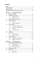
vi About this guide vi P5G41T-M LX2 Series specifications summary viii Chapter 1: Product introduction 1.1 Before you proceed 1-1 1.2 Motherboard overview 1-2 1.2.1 Motherboard layout 1-2 1.2.2 Layout contents 1-3 1.3 Central Processing Unit (CPU 1-3 1.4 System memory 1-4 1.4.1 Overview - Asus P5G41T-M LX2 GB | User Manual - Page 4
Mode 2-11 2.5.2 ACPI 2.0 Support 2-11 2.5.3 ACPI APIC Support 2-11 2.5.4 APM Configuration 2-12 2.5.5 Hardware Monitor 2-12 2.6 Boot menu 2-13 2.6.1 Boot Device Priority 2-13 2.6.2 Boot Settings Configuration 2-13 2.6.3 Security 2-14 2.7 Tools menu 2-15 2.7.1 ASUS EZ Flash 2 2-15 2.8 Exit - Asus P5G41T-M LX2 GB | User Manual - Page 5
used in accordance with manufacturer's instructions, may cause harmful interference to radio connected. • Consult the dealer or an experienced radio/TV technician for help. The use of shielded cables for ASUS REACH website at http://green.asus.com/english/REACH.htm. DO NOT throw the motherboard - Asus P5G41T-M LX2 GB | User Manual - Page 6
. • If you encounter technical problems with the product, contact a qualified service technician or your retailer. About this guide This user guide contains the information you need when installing and configuring the motherboard. How this guide is organized This guide contains the following parts - Asus P5G41T-M LX2 GB | User Manual - Page 7
Instructions that you MUST follow to complete a task. NOTE: Tips and additional information to help you complete a task. Where to find more information Refer to the following sources for additional information and for product and software updates. 1. ASUS websites The ASUS website provides updated - Asus P5G41T-M LX2 GB | User Manual - Page 8
4 x Serial ATA 3Gb/s ports P5G41T-M LX2/GB and P5G41T-M LX2/GB/LPT: Realtek® RTL8112L Gigabit Ethernet PCIe controller P5G41T-M LX2: Realtek® RTL8103EL 10/100Mbps Ethernet PCIe controller VIA® VT1705 High Definition Audio 6-channel CODEC Supports Multi-streaming technology Supports up to 8 USB - Asus P5G41T-M LX2 GB | User Manual - Page 9
-M LX2/GB) 1 x Floppy disk drive connector (optional for P5G41T-M LX2 and P5G41T-M LX2/GB) ASUS CrashFree BIOS 3 ASUS Q-Fan ASUS EZ Flash 2 ASUS MyLogo 2 8Mb Flash ROM, AMI BIOS, PnP, DMI 2.0, WfM 2.0, ACPI 2.0a, SM BIOS 2.5 WOL, PXE, PME Wake up, WOR by Ring Drivers ASUS PC Probe II ASUS Update - Asus P5G41T-M LX2 GB | User Manual - Page 10
down the system and unplug the power cable before removing or plugging in any motherboard component. The illustration below shows the location of the onboard LED. SB_PWR P5G41T-M LX2/GB/LPT ON OFF Standby Power Powered Off P5G41T-M LX2/GB/LPT Onboard power LED 1-1 ASUS P5G41T-M LX2 Series - Asus P5G41T-M LX2 GB | User Manual - Page 11
and P5G41T-M LX2/GB/LPT integrate the Realtek® RTL8112L Gigabit Ethernet controller. • The floppy disk drive connector, chassis intrusion connector, and LPT port are optional items for P5G41T-M LX2 and P5G41T-M LX2/GB. Place six screws into the holes indicated by circles to secure the motherboard - Asus P5G41T-M LX2 GB | User Manual - Page 12
the socket contacts resulting from incorrect CPU installation/removal, or misplacement/loss/incorrect removal of the PnP cap. The motherboard supports Intel® LGA775 processors with the Intel® Enhanced Intel SpeedStep® Technology (EIST) and Hyper-Threading Technology. 1-3 ASUS P5G41T-M LX2 Series - Asus P5G41T-M LX2 GB | User Manual - Page 13
DDR3 DIMM sockets: DIMM_A1 DIMM_B1 Channel Channel A Channel B Sockets DIMM_A1 DIMM_B1 P5G41T-M LX2/GB/LPT P5G41T-M LX2/GB/LPT 240-pin DDR3 more memory on the motherboard. • This motherboard does not support DIMMs made up of 256 megabits (Mb) chips or less. Chapter 1: Product introduction 1-4 - Asus P5G41T-M LX2 GB | User Manual - Page 14
P5G41T-M LX2 Series Motherboard Qualified Vendors Lists (QVL) DDR3-1066MHz capability Vendor Part No. Size SS/ Chip DS Brand Chip NO. Timing Dimm (Bios) Voltage Crucial CT12864BA1067.8FF 1024MB SS Crucial CT25664BA1067.16FF 2048MB DS Elpida EBJ51UD8BAFA-AC-E 512MB SS Elpida - Asus P5G41T-M LX2 GB | User Manual - Page 15
system unstable and the card inoperable. 1.5.3 PCI slots The PCI slot supports cards such as a LAN card, SCSI card, USB card, and other cards that comply with PCI specifications. 1.5.4 PCI Express x16 slot This motherboard supports a PCI Express x16 graphics card that complies with the PCI Express - Asus P5G41T-M LX2 GB | User Manual - Page 16
You do not need to clear the RTC when the system hangs due to overclocking. For system failure due to overclocking, use the CPU Parameter Recall (C.P.R.) feature. Shut down and reboot the system, then the BIOS automatically resets parameter settings to default values. 1-7 ASUS P5G41T-M LX2 Series - Asus P5G41T-M LX2 GB | User Manual - Page 17
setting in the BIOS. KBPWR 12 23 +5V +5VSB (Default) P5G41T-M LX2/GB/LPT P5G41T-M LX2/GB/LPT Keyboard Power Setting CPU, DRAM in slow refresh, power supply in reduced power mode). USBPW1-4 12 23 +5V +5VSB (Default) USBPW5-8 P5G41T-M LX2/GB/LPT 12 23 +5V +5VSB (Default) P5G41T-M LX2/GB/LPT - Asus P5G41T-M LX2 GB | User Manual - Page 18
Description No link 10Mbps connection LED LED (Orange) (Green) LAN port P5G41T-M LX2/GB and P5G41T-M LX2/GB/LPT LAN port LED indications Activity/Link LED Status Description OFF No link for the function of the audio ports in 2, 4, or 6-channel configuration. 1-9 ASUS P5G41T-M LX2 Series - Asus P5G41T-M LX2 GB | User Manual - Page 19
P5G41T-M LX2/GB/LPT +5 Volts GND PSON# GND +3 Volts -12 Volts +3 Volts +3 Volts PIN 1 P5G41T-M LX2/GB/LPT ATX power connectors • For a fully configured system, we recommend that you use a power supply unit (PSU) that complies with ATX 12V Specification at http://support.asus. com/PowerSupplyCalculator/PSCalculator - Asus P5G41T-M LX2 GB | User Manual - Page 20
may damage the motherboard components. These are not jumpers! Do not place jumper caps on the fan connectors! Only the 4-pin CPU fan supports the ASUS Q-Fan feature. P5G41T-M LX2/GB/LPT CHA_FAN Rotation +12V GND CPU_FAN CPU FAN PWM CPU FAN IN CPU FAN PWR GND P5G41T-M LX2/GB/LPT fan connectors - Asus P5G41T-M LX2 GB | User Manual - Page 21
connector to the motherboard's IDE connector, then select one of the following modes to configure your device. PIN1 PRI_IDE P5G41T-M LX2/GB/LPT NOTE:Orient the red markings on the IDE ribbon cable to PIN 1. P5G41T-M LX2/GB/LPT IDE connector Single device Two devices Drive jumper setting Cable - Asus P5G41T-M LX2 GB | User Manual - Page 22
opening at the back of the system chassis. These USB connectors comply with USB 2.0 specification that supports up to 480Mbps connection speed. USB+5V USB_P8USB_P8+ GND NC USB+5V USB_P6USB_P6+ GND NC P5G41T-M LX2/GB/LPT USB56 PIN 1 USB78 PIN 1 USB+5V USB_P7USB_P7+ GND USB+5V USB_P5USB_P5+ GND - Asus P5G41T-M LX2 GB | User Manual - Page 23
module that supports either HD Audio P5G41T-M LX2/GB/LPT HD-audio-compliant Legacy AC'97 pin definition compliant definition P5G41T-M LX2/GB/LPT Front panel audio connector • We recommend that you connect a high-definition front panel audio module to this connector to avail of the motherboard - Asus P5G41T-M LX2 GB | User Manual - Page 24
+ IDE_LED- Ground Reset 10. System panel connector (10-1 pin F_PANEL) This connector supports several chassis-mounted functions. F_PANEL PWR LED PWR BTN PIN 1 P5G41T-M LX2/GB/LPT HD LED RESET P5G41T-M LX2/GB/LPT System panel connector • System power LED (2-pin PLED) This 2-pin connector is for - Asus P5G41T-M LX2 GB | User Manual - Page 25
to avail all motherboard features. The contents of the Support DVD are subject to change at any time without notice. Visit the ASUS website at www.asus.com for updates. To run the Support DVD Place the Support DVD to the optical drive. The DVD automatically displays the Drivers menu if Autorun - Asus P5G41T-M LX2 GB | User Manual - Page 26
is available in the support DVD that comes with the motherboard package. Installing ASUS Update To install ASUS Update: 1. Place the support DVD in the optical drive. The Drivers menu appears. 2. Click the Utilities tab, then click ASUS Update. 3. Follow the onscreen instructions to complete the - Asus P5G41T-M LX2 GB | User Manual - Page 27
Current ROM BOARD:P5G41T-M LX2/GB/LPT VER:0305 (H:00 B:00) DATE: 10/29/2009 Update ROM BOARD: Unknown VER: Unknown DATE: Unknown PATH: A:\ A: Note [Enter] Select or Load [Tab] Switch [Up/Down/Home/End] Move [B] Backup [V] Drive Info [ESC] Exit • This function supports USB flash disks - Asus P5G41T-M LX2 GB | User Manual - Page 28
file using the motherboard support DVD or a removable device that contains the updated BIOS file. • Before using this utility, rename the BIOS file in the removable device into PG41TML2.ROM (P5G41T-M LX2) / PG41TMLG.ROM (P5G41T-M LX2/GB) / PG41TMLP.ROM (P5G41T-M LX2/GB/LPT). • The BIOS file in the - Asus P5G41T-M LX2 GB | User Manual - Page 29
Sets the system date. 2.3.3 Legacy Diskette A [1.44M, 3.5 in.] Sets the type of floppy drive installed. Configuration options: [Disabled] [360K, 5.25 in.] [1.2M, 5.25 in.] [720K, 3.5 in.] [1.44M, 3.5 in.] [2.88M, 3.5 in.] This item is for P5G41T-M LX2/GB/LPT only. Chapter 2: BIOS information 2-4 - Asus P5G41T-M LX2 GB | User Manual - Page 30
SATA device information. The BIOS automatically detects the values drive. Setting to Auto allows automatic selection of the appropriate IDE device type. Select CDROM if you are specifically configuring a CD-ROM drive time if the device supports multi-sector transfer feature. ASUS P5G41T-M LX2 Series - Asus P5G41T-M LX2 GB | User Manual - Page 31
options: [Disabled] [Compatible] [Enhanced] Enhanced Mode Support On [S-ATA] Sets Serial ATA, Parallel ATA or specifications. The BIOS automatically detects the items in this menu. BIOS Information Displays the auto-detected BIOS information. Processor Displays the auto-detected CPU specification - Asus P5G41T-M LX2 GB | User Manual - Page 32
operating system to use the EIST feature. Set this item to [Disabled] if you do not want to use the EIST. Configuration options: [Enabled] [Disabled] 2-7 ASUS P5G41T-M LX2 Series - Asus P5G41T-M LX2 GB | User Manual - Page 33
the front panel support type. If High Definition Audio Front Panel is used, set this item to [HD Audio]. Configuration options: [AC97] [HD Audio] Onboard Gigabit LAN [Enabled] Enables or disables the onboard LAN controller. Configuration options: [Enabled] [Disabled] For P5G41T-M LX2, this item - Asus P5G41T-M LX2 GB | User Manual - Page 34
mode for Serial Port1. Configuration options: [Normal] The following item is for P5G41T-M LX2/GB/LPT with an LPT port at the back panel. Parallel Port Address [378] Allows you to select IRQ7] Allows you to select parallel port IRQ. Configuration options: [IRQ5] [IRQ7] 2-9 ASUS P5G41T-M LX2 Series - Asus P5G41T-M LX2 GB | User Manual - Page 35
Legacy USB Support [Auto] Enables or disables support for Legacy USB storage devices, including USB flash drives and USB hard drives. Setting Storage Reset Delay [20 Sec] Allows you to set the maximum time that the BIOS waits for the USB storage device to initialize. Configuration options: [10 Sec] - Asus P5G41T-M LX2 GB | User Manual - Page 36
this item is set to [No], BIOS configures all the devices in the support in the Application-Specific Integrated Circuit (ASIC). When this item is set to [Enabled], the ACPI APIC table pointer is included in the RSDT pointer list. Configuration options: [Disabled] [Enabled] 2-11 ASUS P5G41T-M LX2 - Asus P5G41T-M LX2 GB | User Manual - Page 37
5VSB lead. Configuration options: [Disabled] [Enabled] 2.5.5 Hardware Monitor CPU Temperature [xxxºC/xxxºF] or [Ignored] MB Temperature [xxxºC/xxxºF] or [Ignored] The onboard hardware monitor automatically detects and displays the motherboard and CPU temperatures. Select [Ignored] if you do not want - Asus P5G41T-M LX2 GB | User Manual - Page 38
A virtual floppy disk drive (Floppy Drive B: ) may appear when you set the CD-ROM drive as the first boot decrease the time needed to boot the system. When set to [Disabled], BIOS performs all the POST items. Configuration options: [Disabled] [Enabled] Full [Enabled] 2-13 ASUS P5G41T-M LX2 Series - Asus P5G41T-M LX2 GB | User Manual - Page 39
press twice. The message Password uninstalled appears. If you forget your BIOS password, you can clear it by erasing the CMOS Real Time Clock (RTC) RAM. See section 1.6 Jumpers for information on how to erase the RTC RAM. After you have set a supervisor password, the other items appear to - Asus P5G41T-M LX2 GB | User Manual - Page 40
sub-menu. Main Advanced Power BIOS SETUP UTILITY Boot Tools Exit ASUS EZ Flash 2 Press ENTER to run the utility to select and update BIOS. This utility supports 1.FAT 12/16/32 (r/w) -eEreopioemslxnntmecpinrtteheisn 2-15 ASUS P5G41T-M LX2 Series
-
 1
1 -
 2
2 -
 3
3 -
 4
4 -
 5
5 -
 6
6 -
 7
7 -
8
-
9
-
10
-
11
-
12
-
13
-
14
-
15
-
16
-
17
-
18
-
19
-
20
-
21
-
22
-
23
-
24
-
25
-
26
-
27
-
28
-
29
-
30
-
31
-
32
-
33
-
34
-
35
-
36
-
37
-
38
-
39
-
40
 |
 |

Motherboard
P5G41T-M LX2 Series
• P5G41T-M LX2
• P5G41T-M LX2/GB
• P5G41T-M LX2/GB/LPT