Asus P5VD1-X Motherboard Installation Guide
Asus P5VD1-X Manual
 |
View all Asus P5VD1-X manuals
Add to My Manuals
Save this manual to your list of manuals |
Asus P5VD1-X manual content summary:
- Asus P5VD1-X | Motherboard Installation Guide - Page 1
P5VD1-X Motherboard - Asus P5VD1-X | Motherboard Installation Guide - Page 2
T2180 © 2005 2 - Asus P5VD1-X | Motherboard Installation Guide - Page 3
3 - Asus P5VD1-X | Motherboard Installation Guide - Page 4
4 - Asus P5VD1-X | Motherboard Installation Guide - Page 5
5 - Asus P5VD1-X | Motherboard Installation Guide - Page 6
6 - Asus P5VD1-X | Motherboard Installation Guide - Page 7
7 - Asus P5VD1-X | Motherboard Installation Guide - Page 8
12 Jumper Mode 23 Jumper Free (Default) 8 - Asus P5VD1-X | Motherboard Installation Guide - Page 9
P5VD1-X-TAYZ 6 10839 11036 0 11XXX11XXX11 9 - Asus P5VD1-X | Motherboard Installation Guide - Page 10
® ® 10 - Asus P5VD1-X | Motherboard Installation Guide - Page 11
11 - Asus P5VD1-X | Motherboard Installation Guide - Page 12
12 - Asus P5VD1-X | Motherboard Installation Guide - Page 13
- Asus P5VD1-X | Motherboard Installation Guide - Page 14
- Asus P5VD1-X | Motherboard Installation Guide - Page 15
1-1 - Asus P5VD1-X | Motherboard Installation Guide - Page 16
® ® 1-2 - Asus P5VD1-X | Motherboard Installation Guide - Page 17
® ® ® 1-3 - Asus P5VD1-X | Motherboard Installation Guide - Page 18
1-4 - Asus P5VD1-X | Motherboard Installation Guide - Page 19
- Asus P5VD1-X | Motherboard Installation Guide - Page 20
- Asus P5VD1-X | Motherboard Installation Guide - Page 21
P5VD1-X ® P5VD1-X Onboard LED SB_PWR ON Standby Power OFF Powered Off 2-1 - Asus P5VD1-X | Motherboard Installation Guide - Page 22
2-2 P5VD1-X ® - Asus P5VD1-X | Motherboard Installation Guide - Page 23
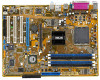
:Line In Center:Line Out Below:Mic In CPU_FAN VIA PT880Ultra PRI_IDE Intel 82540EM AD1888 CD AUX FP_AUDIO AGP CR2032 3V Lithium Cell CMOS Power P5VD1-X PCIEX16 ® PCI1 VIA VT8237R CHA_FAN SATA1 SATA2 PCI2 SB_PWR PCI3 FLOPPY 4Mb BIOS USBPW56 USBPW78 USB56 USB78 GAME Super I/O PANEL CLRTC - Asus P5VD1-X | Motherboard Installation Guide - Page 24
P5VD1-X ® P5VD1-X CPU Socket 775 2-4 - Asus P5VD1-X | Motherboard Installation Guide - Page 25
A B B A 2-5 - Asus P5VD1-X | Motherboard Installation Guide - Page 26
A B 2-6 - Asus P5VD1-X | Motherboard Installation Guide - Page 27
® ® • ® ® ® • ® ® • 2-7 - Asus P5VD1-X | Motherboard Installation Guide - Page 28
A B B A B A A B CPU FAN PWM CPU FAN IN CPU FAN PWR GND CPU_FAN P5VD1-X ® P5VD1-X CPU Fan connector 2-8 - Asus P5VD1-X | Motherboard Installation Guide - Page 29
104 Pins 80 Pins DIMM_A1 DIMM_A2 DIMM_B1 DIMM_B2 P5VD1-X ® P5VD1-X 184-pin DDR DIMM sockets • • • 2-9 - Asus P5VD1-X | Motherboard Installation Guide - Page 30
2-10 - Asus P5VD1-X | Motherboard Installation Guide - Page 31
2-11 - Asus P5VD1-X | Motherboard Installation Guide - Page 32
2 1 1 2-12 2 1 1 - Asus P5VD1-X | Motherboard Installation Guide - Page 33
2-13 - Asus P5VD1-X | Motherboard Installation Guide - Page 34
A B CD E F GH 2-14 - Asus P5VD1-X | Motherboard Installation Guide - Page 35
P5VD1-X ® Keyed for 1.5v P5VD1-X Accelerated Graphics Port (AGP) 2-15 - Asus P5VD1-X | Motherboard Installation Guide - Page 36
2-16 - Asus P5VD1-X | Motherboard Installation Guide - Page 37
2-17 - Asus P5VD1-X | Motherboard Installation Guide - Page 38
P5VD1-X ® P5VD1-X Clear RTC RAM CLRTC 12 23 Normal (Default) Clear CMOS 2-18 - Asus P5VD1-X | Motherboard Installation Guide - Page 39
USBPW12 USBPW34 12 23 P5VD1-X ® +5V (Default) +5VSB USBPW56 USBPW78 12 23 +5V P5VD1-X USB device wake up (Default) +5VSB 2-19 - Asus P5VD1-X | Motherboard Installation Guide - Page 40
1 2 11 10 9 3 4 5 6 8 7 2-20 - Asus P5VD1-X | Motherboard Installation Guide - Page 41
2-21 - Asus P5VD1-X | Motherboard Installation Guide - Page 42
P5VD1-X R FLOPPY PIN 1 P5VD1-X Floppy disk drive connector PRI_IDE SEC_IDE P5VD1-X R P5VD1-X IDE connectors • • PIN 1 2-22 - Asus P5VD1-X | Motherboard Installation Guide - Page 43
P5VD1-X ® SATA1 SATA2 GND RSATA_TXP1 RSATA_TXN1 GND RSATA_RXP1 RSATA_RXN1 GND GND RSATA_TXP2 RSATA_TXN2 GND RSATA_RXP2 RSATA_RXN2 GND P5VD1-X SATA connectors • • 2-23 - Asus P5VD1-X | Motherboard Installation Guide - Page 44
2-24 P5VD1-X ® USB56 1 P5VD1-X USB 2.0 connectors USB+5V USB_P5USB_P5+ GND USB+5V USB_P6USB_P6+ GND NC USB78 1 USB+5V USB_P7USB_P7+ GND USB+5V USB_P8USB_P8+ GND NC CPU_FAN CHA_FAN P5VD1-X ® P5VD1-X Fan connectors CPU FAN PWM CPU FAN IN CPU FAN PWR GND GND +12V Rotation - Asus P5VD1-X | Motherboard Installation Guide - Page 45
• ATXPWR ATX12V GND +12V DC +3 Volts +12 Volts +12 Volts +5V Standby Power OK P5VD1-X GND +12V DC Ground +5 Volts ® Ground +5 Volts Ground P5VD1-X ATX power connectors +3 Volts +3 Volts Ground +5 Volts +5 Volts +5 Volts -5 Volts Ground Ground Ground PSON# Ground -12 Volts +3 Volts - Asus P5VD1-X | Motherboard Installation Guide - Page 46
P5VD1-X ® CD(Black) AUX(White) Left Audio Channel Ground Ground Right Audio Channel Left Audio Channel Ground Ground Right Audio Channel P5VD1-X Internal audio connectors +5V J1B2 J1CY GND GND J1CX J1B1 +5V MIDI_IN J2B2 J2CY MIDI_OUT J2CX J2B1 +5V P5VD1-X ® P5VD1-X Game connector GAME 2-26 - Asus P5VD1-X | Motherboard Installation Guide - Page 47
2-27 P5VD1-X Front panel audio connector MIC2 MICPWR Line out_R NC Line out_L FP_AUDIO P5VD1-X ® AGND +5VA BLINE_OUT_R BLINE_OUT_L - Asus P5VD1-X | Motherboard Installation Guide - Page 48
PLED SPEAKER PLED+ PLED+5V Ground Ground Speaker PANEL IDE_LED+ IDE_LED- PWR Ground Reset Ground P5VD1-X ® RESET IDE_LED PWRSW * Requires an ATX power supply. P5VD1-X System Panel connector • 2-28 - Asus P5VD1-X | Motherboard Installation Guide - Page 49
- Asus P5VD1-X | Motherboard Installation Guide - Page 50
- Asus P5VD1-X | Motherboard Installation Guide - Page 51
3-1 - Asus P5VD1-X | Motherboard Installation Guide - Page 52
3-2 - Asus P5VD1-X | Motherboard Installation Guide - Page 53
- Asus P5VD1-X | Motherboard Installation Guide - Page 54
- Asus P5VD1-X | Motherboard Installation Guide - Page 55
4-1 - Asus P5VD1-X | Motherboard Installation Guide - Page 56
EZFlash starting BIOS update Checking for floppy... EZFlash starting BIOS update Checking for floppy... Floppy found! Reading file "P5VD1-X.ROM". Completed. Start erasing.......| Start Programming...| Flashed successfully. Rebooting. • • 4-2 - Asus P5VD1-X | Motherboard Installation Guide - Page 57
• • A:\>afudos /oOLDBIOS1.ROM A:\>afudos /oOLDBIOS1.ROM AMI Firmware Update Utility - Version 1.10 Copyright (C) 2002 American Megatrends, Inc. All rights reserved. Reading flash ..... done A:\> 4-3 - Asus P5VD1-X | Motherboard Installation Guide - Page 58
, Inc. All rights reserved. Reading file ..... done Erasing flash .... done Writing flash .... 0x0008CC00 (9%) A:\>afudos /iP5VD1-X.ROM AMI Firmware Update Utility - Version 1.10 Copyright (C) 2002 American Megatrends, Inc. All rights reserved. Reading file ..... done Erasing flash .... done Writing - Asus P5VD1-X | Motherboard Installation Guide - Page 59
Bad BIOS checksum. Starting BIOS recovery... Checking for floppy... Bad BIOS checksum. Starting BIOS recovery... Checking for floppy... Floppy found! Reading file "P5VD1-X.ROM". Completed. Start flashing... 4-5 - Asus P5VD1-X | Motherboard Installation Guide - Page 60
Bad BIOS checksum. Starting BIOS recovery... Checking for floppy... Bad BIOS checksum. Starting BIOS recovery... Checking for floppy... Floppy not found! Checking for CD-ROM... CD-ROM found. Reading file "P5VD1-X.ROM". Completed. Start flashing... 4-6 - Asus P5VD1-X | Motherboard Installation Guide - Page 61
4-7 - Asus P5VD1-X | Motherboard Installation Guide - Page 62
4-8 - Asus P5VD1-X | Motherboard Installation Guide - Page 63
4-9 - Asus P5VD1-X | Motherboard Installation Guide - Page 64
4-10 - Asus P5VD1-X | Motherboard Installation Guide - Page 65
IDE Slave Secondary IDE Master Secondary IDE Slave Third IDE Master Fourth IDE Master IDE Configuration System Information [11:10:19] [Thu 03/27/2003] [1.44M, 3.5 in] [English] :[ST320413A] :[ASUS CD-S340] :[Not Detected] :[Not Detected] :[Not Detected] :[Not Detected] Use [ENTER], [TAB] or [SHIFT - Asus P5VD1-X | Motherboard Installation Guide - Page 66
IDE Master IDE Configuration System Information [11:10:19] [Thu 03/27/2003] [1.44M, 3.5 in] [English] :[ST320413A] :[ASUS CD-S340] :[Not Detected Chipset settings WARNING: Setting wrong values in the sections below may cause system to malfunction. Configure DRAM Timing by SPD Memory Acceleration - Asus P5VD1-X | Motherboard Installation Guide - Page 67
Diskette B Primary IDE Master Primary IDE Slave Third IDE Master Third IDE Slave Fourth IDE Master Fourth IDE Slave IDE Configuration System Information [11:51:19] [Thu 05/07/2004] [1.44M, 3.5 in] [Disabled] : [ST320413A] : [Not Detected] : [Not Detected] : [Not Detected] : [Not Detected] : [Not - Asus P5VD1-X | Motherboard Installation Guide - Page 68
IDE Master Device : Hard Disk Vendor : ST320413A Size : 20.0GB LBA Mode : Supported Block Mode : 16 Sectors PIO Mode : Supported Async DMA : MultiWord DMA-2 Ultra DMA : Ultra DMA-5 SMART Monitoring: Supported Type LBA/Large Mode Block(Multi-sector Transfer) PIO Mode DMA Mode Smart - Asus P5VD1-X | Motherboard Installation Guide - Page 69
AMIBIOS Version : 08.00.10 Build Date : 04/07/04 Processor Type Speed Count : Genuine Intel(R) CPU 3.20GHz : 2800 MHz : 1 System Memory Size : 512MB 4-15 - Asus P5VD1-X | Motherboard Installation Guide - Page 70
USB Configuration CPU Configuration Chipset Onboard Devices Configuration PCI PnP Configure CPU. Configure System Frequency/Voltage AI Overclocking Tuner CPU Frequency AGP/PCI Frequency [Manual] [200] [Auto] Spread Spectrum [OverSpectrum 0.30%] Select the target CPU frequency, and - Asus P5VD1-X | Motherboard Installation Guide - Page 71
Version - 2.24.0-10.4 USB Devices Enabled: 1 Mouse USB 1.1 Ports Configuration USB 2.0 Ports Enable VIA USB Device Function Enable Legacy USB Support Port 64/60 Emulation USB 2.0 Controller Mode BIOS EHCI Hand-Off [USB 8 Ports] [Enable] [Disabled] [Enabled] [Disabled] [FullSpeed] [Enabled] 4-17 - Asus P5VD1-X | Motherboard Installation Guide - Page 72
Configure Advanced CPU settings Manufacturer: Intel Brand String: Genuine Intel(R) CPU 3.20GHz Frequency : 3200 MHz FSB Speed : 800 Line Prefetch CPU Internal Thermal Control Hyper Threading Technology [16] [Disabled] [Enabled] [Enabled] [Auto] [Disabled] Sets the ratio between CPU Core Clock and - Asus P5VD1-X | Motherboard Installation Guide - Page 73
Advanced Chipset Settings WARNING: Setting wrong values in below sections may cause system to malfunction. Options for VIA PT880U NorthBridge VIA PT880Ultra Configuration SouthBridge VIA VT8237R Configuration Select Screen Select Item +- Change Option F1 General Help F10 Save and Exit ESC Exit - Asus P5VD1-X | Motherboard Installation Guide - Page 74
DRAM Timing DRAM CAS Latency Precharge to Active(Trp) Active to Precharge(Tras) Active to CMD(Trcd) DRAM BUS Selection [Auto] [Manual] [2.5] [4T] [7T] [4T] [Auto] Manual DRAM Frequency Setting or AUTO by SPD Select Screen Select Item +- Change Option F1 General Help F10 Save and Exit ESC Exit - Asus P5VD1-X | Motherboard Installation Guide - Page 75
Size Primary Graphics Adapter [8X] [Enabled] [128MB] [PCI Express] Select Option To Set AGP MODE Select Screen Select Item +- Change Option F1 General Help F10 Save and Exit ESC Exit V-Link mode selection V-Link Data 2X Support [Mode 1] [Disabled] Select V-Link Mode Select Screen Select - Asus P5VD1-X | Motherboard Installation Guide - Page 76
PCI Delay Transaction OnBoard SATA-IDE RAID BIOS Execute Onboard AC'97 [Disabled] [RAID] [Enabled] [Enabled] Options for DRAM Select Screen Select Item +- Change Option F1 General Help F10 Save and Exit ESC Exit 4-22 - Asus P5VD1-X | Motherboard Installation Guide - Page 77
Win627EHF Super IO Chipset Serial Port2 Address Serial Port2 Mode Parallel Port Address Parallel Mode ECP Mode DMA Channel Parallel Port IRQ OnBoard Game.MIDI Port [2F8/IRQ3] [Normal] [378] [ECP] [DMA3] [IRQ7] [Disabled] OnBoard LAN Onboard LAN Boot ROM [Enabled] [Disabled] Allow BIOS to Select - Asus P5VD1-X | Motherboard Installation Guide - Page 78
/PnP Settings WARNING: Setting wrong values in below sections may cause system to malfunction. Plug And Play O/S PCI Latency Timer Allocate IRQ to PCI VGA Palette Snooping [No] [64] [Yes] [Disabled] IRQ-3 assigned to IRQ-4 assigned to IRQ-5 assigned to IRQ-7 assigned to IRQ-9 assigned to IRQ-10 - Asus P5VD1-X | Motherboard Installation Guide - Page 79
Suspend Mode ACPI 2.0 Support ACPI APIC Support APM Configuration Hardware Monitor [S1 (POS) only] [No] [Enabled] Configure CPU. 4-25 - Asus P5VD1-X | Motherboard Installation Guide - Page 80
Power Management [Enabled] Power Button Mode Restore on AC Power Lose [On/Off] [Last State] Advanced Resume Events Control Resume on Ring Resume on PME# Resume on KB Wake-Up Key Resume on By PS/2 Mouse Resume on RTC Alarm [Disabled] [Disabled] [Disabled] [Any - Asus P5VD1-X | Motherboard Installation Guide - Page 81
Hardware Monitor CPU Temperature MB Temperature CPU Fan Speed CPU Q-Fan Control CPU Target Temperature Chassis Fan Speed VCORE Voltage 3.3V Voltage 5V Voltage 12V Voltage [48ºC/118.5ºF] [32ºC/89.5ºF] [2393 RPM] [Disabled] [50° C] [N/A] [ 1.376V] [ 3.296V] [ 5.208V] [11.510V] CPU Temperature Select - Asus P5VD1-X | Motherboard Installation Guide - Page 82
4-28 - Asus P5VD1-X | Motherboard Installation Guide - Page 83
APM Configuration Boot Device Priority Boot Settings Configuration Security Select Screen Select Item Enter Go to Sub-screen F1 General Help F10 Save and Exit ESC Exit Boot Device Priority 1st Boot Device 2nd Boot Device 3rd Boot Device [1st FLOPPY DRIVE] [PM-ST330620A] [PS-ASUS CD-S360] 4-29 - Asus P5VD1-X | Motherboard Installation Guide - Page 84
Full Screen Logo AddOn ROM Display Mode Bootup Num-Lock PS/2 Mouse Support Wait For 'F1' If Error Hit 'DEL' Message Display Interrupt 19 Capture [Enabled] [Enabled] [Force BIOS] [On] [Auto] [Enabled] [Enabled] [Disabled] Allows BIOS to skip certain tests while booting. This will decrease the time - Asus P5VD1-X | Motherboard Installation Guide - Page 85
Security Settings Supervisor Password : Not Installed User Password : Not Installed Change Supervisor Password Boot Sector Virus Protection [Disabled] to change password. again to disabled password. 4-31 - Asus P5VD1-X | Motherboard Installation Guide - Page 86
Security Settings Supervisor Password : Not Installed User Password : Not Installed Change Supervisor Password User Access Level Change User Password Clear User Password Password Check [Full Access] [Setup] Boot Sector Virus Protection [Disabled] Select Screen Select Item 4-32 - Asus P5VD1-X | Motherboard Installation Guide - Page 87
Exit Options Exit & Save Changes Exit & Discard Changes Discard Changes Load Setup Defaults Exit system setup after saving the changes. F10 key can be used for this operation. Select Screen Select Item Enter Go to Sub-screen F1 General Help F10 Save and Exit ESC Exit 4-33 - Asus P5VD1-X | Motherboard Installation Guide - Page 88
4-34 - Asus P5VD1-X | Motherboard Installation Guide - Page 89
- Asus P5VD1-X | Motherboard Installation Guide - Page 90
- Asus P5VD1-X | Motherboard Installation Guide - Page 91
5-1 - Asus P5VD1-X | Motherboard Installation Guide - Page 92
5-2 - Asus P5VD1-X | Motherboard Installation Guide - Page 93
5-3 - Asus P5VD1-X | Motherboard Installation Guide - Page 94
5-4 - Asus P5VD1-X | Motherboard Installation Guide - Page 95
5-5 - Asus P5VD1-X | Motherboard Installation Guide - Page 96
5-6 - Asus P5VD1-X | Motherboard Installation Guide - Page 97
5-7 - Asus P5VD1-X | Motherboard Installation Guide - Page 98
5-8 - Asus P5VD1-X | Motherboard Installation Guide - Page 99
5-9 - Asus P5VD1-X | Motherboard Installation Guide - Page 100
array with the hard disks attached to VIA RAID controller F1 : View Array/Disk Status ↑,↓ : Move to next item Enter : Confirm the selection ESC : Exit Channel Drive Name Array Name Mode Size(GB) Status Serial_Ch0 Master XXXXXXXXXXX ARRAY 0 SATA 999.99 XXXXXXX Serial_Ch1 Master XXXXXXXXXXX ARRAY - Asus P5VD1-X | Motherboard Installation Guide - Page 101
RAID 0 for performance RAID 1 for Data Protection RAID SPAN for capacity Auto create array will destroy all data on disks, Continue? (Y/N) 4K 8K 16K 32K 64K The data on the selected disks will be destroyed. Continue? Press Y/N 5-11 - Asus P5VD1-X | Motherboard Installation Guide - Page 102
RAID 0 for performance RAID 1 for Data Protection RAID 0/1 RAID SPAN for capacity Auto create array will destroy all data on disks, Continue? (Y/N) 5-12 Save the data on source disk to mirror after creation? (Y/N) Duplicating..... RAID 1 for data protection Press Yes(Y) to Escape The data on the - Asus P5VD1-X | Motherboard Installation Guide - Page 103
5-13 - Asus P5VD1-X | Motherboard Installation Guide - Page 104
5-14
-
 1
1 -
 2
2 -
 3
3 -
 4
4 -
 5
5 -
 6
6 -
 7
7 -
8
-
9
-
10
-
11
-
12
-
13
-
14
-
15
-
16
-
17
-
18
-
19
-
20
-
21
-
22
-
23
-
24
-
25
-
26
-
27
-
28
-
29
-
30
-
31
-
32
-
33
-
34
-
35
-
36
-
37
-
38
-
39
-
40
-
41
-
42
-
43
-
44
-
45
-
46
-
47
-
48
-
49
-
50
-
51
-
52
-
53
-
54
-
55
-
56
-
57
-
58
-
59
-
60
-
61
-
62
-
63
-
64
-
65
-
66
-
67
-
68
-
69
-
70
-
71
-
72
-
73
-
74
-
75
-
76
-
77
-
78
-
79
-
80
-
81
-
82
-
83
-
84
-
85
-
86
-
87
-
88
-
89
-
90
-
91
-
92
-
93
-
94
-
95
-
96
-
97
-
98
-
99
-
100
-
101
-
102
-
103
-
104
 |
 |

Motherboard
P5VD1-X