Asus PRIME X470-PRO E11133MBPinDefinition English
Asus PRIME X470-PRO Manual
 |
View all Asus PRIME X470-PRO manuals
Add to My Manuals
Save this manual to your list of manuals |
Asus PRIME X470-PRO manual content summary:
- Asus PRIME X470-PRO | E11133MBPinDefinition English - Page 1
1 Motherboard Pin Definition E11133 Revised Edition v2 December 2015 E11133_MB_pin_definition_v2.indd 1 2015/12/28 17:21:46 - Asus PRIME X470-PRO | E11133MBPinDefinition English - Page 2
Contents Motherboard Pin Definition 1-1 1 Headers...1-3 2 Jumpers...1-4 3 Internal Connectors 1-6 4 Onboard LEDs 1-16 5 Onboard buttons and switches 1-17 1-2 E11133_MB_pin_definition_v2.indd 2 Motherboard Pin Definition 2015/12/28 17:21:46 - Asus PRIME X470-PRO | E11133MBPinDefinition English - Page 3
again to clear the CMOS RTC RAM data. After clearing the CMOS, CPU Parameter Recall (C.P.R.) feature. Shut down and reboot the system, then the BIOS automatically resets parameter settings to default values. 2. RTC Battery header (2-pin BATT_CON) This connector Motherboard Pin Definition E11133_MB_pin_definition_v2.indd 3 1-3 2015/12 - Asus PRIME X470-PRO | E11133MBPinDefinition English - Page 4
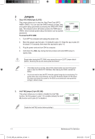
the boot process and enter BIOS setup to reenter data. Except when clearing the RTC RAM, never remove the cap on the CPU Parameter Recall (C.P.R) feature. Shut down and reboot the system so the BIOS updating it. 1-4 E11133_MB_pin_definition_v2.indd 4 Motherboard Pin Definition 2015/12/28 17:21:47 - Asus PRIME X470-PRO | E11133MBPinDefinition English - Page 5
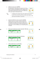
S4 sleep modes (no power to CPU, DRAM in slow +5V +5VSB BIOS. 12 23 KB_USBPWB +5V +5VSB (Default) 5. Display panel panel/eDP selector (3-pin FPD_SEL) Pins 1-2 (Default) 2-3 Setting LVDS eDP VCC_PWR_SEL 1 3V (Default) 2 5V 3 12V FPD_SEL 12 23 for LVDS (Default) for eDP Motherboard - Asus PRIME X470-PRO | E11133MBPinDefinition English - Page 6
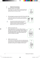
CPU_FAN connector supports a CPU fan of maximum 1A (12 W) fan power. USB3+5V IntA_P1_SSRXIntA_P1_SSRX+ GND IntA_P1_SSTXIntA_P1_SSTX+ GND IntA_P1_DIntA_P1_D+ GND 3. USB 3.0 connector (20-1 pin) This connector allows you to connect a USB 3.0 module for additional USB 3.0 front or rear panel ports - Asus PRIME X470-PRO | E11133MBPinDefinition English - Page 7
your system, refer to the Recommended Power Supply Wattage Calculator at http://support.asus. com/PowerSupplyCalculator/PSCalculator.aspx?SLanguage=en-us for details. 7. Speaker connector (4-pin SPEAKER) The 4-pin connector is for the chassis-mounted system warning speaker. The speaker allows you - Asus PRIME X470-PRO | E11133MBPinDefinition English - Page 8
a high-definition front panel audio module to this connector to avail of the motherboard's high-definition connector (26-1 pin LPT) The LPT (Line Printing Terminal) connector supports devices such as a printer. LPT standardizes as IEEE 1284, which is the parallel port interface on IBM PC-compatible - Asus PRIME X470-PRO | E11133MBPinDefinition English - Page 9
LVDS in the BIOS setup if the LVDS connectors (7-pin SATA6G) These connectors connect to SATA 6.0 Gb/s hard disk drives via SATA 6.0 Gb/s signal cables. SATA6G You must install Windows® XP Service the onboard Intel® chipset. The SATAEXPRESS connector can support one SATA Express device or two SATA - Asus PRIME X470-PRO | E11133MBPinDefinition English - Page 10
panel connector (20-8 pin PANEL) This connector supports or soft-off mode depending on the BIOS settings. Pressing the power button for more connector is for the chassis-mounted reset button for system reboot without turning off the system power. 1-10 E11133_MB_pin_definition_v2.indd 10 Motherboard - Asus PRIME X470-PRO | E11133MBPinDefinition English - Page 11
System panel connector (20-5 pin PANEL) This connector supports several chassis-mounted functions. • System power LED (4-pin +PWR_LED-) PANEL +PWR_LED- PWR_SW SPEAKER PLED+ PLEDPWR Ground +5V_SPKO Ground Ground Speaker This 2-pin connector is for the system power LED. Connect the chassis power - Asus PRIME X470-PRO | E11133MBPinDefinition English - Page 12
System panel connector (20-3 pin F_PANEL) This connector supports several chassis-mounted functions. • System power LED (4-pin +PWR_LED-) PANEL +PWR_LED- PWR_SW SPEAKER PLED+ PLEDPWR GND +5V GND GND Speaker Intruder# This 2-pin connector is for the system power LED. Connect the chassis power - Asus PRIME X470-PRO | E11133MBPinDefinition English - Page 13
TPM connector (14-1 pin TPM) PWRDWN F_SERIRQ F_FRAME# F_LAD3 F_LAD2 F_LAD1 F_LAD0 This connector supports a an M.2 E key Wi-Fi and Wi-Fi based combo device. M.2(WIFI) VCC VCC NC NC NC NC NC NC GND NC NC NC NC Motherboard Pin Definition E11133_MB_pin_definition_v2.indd 13 1-13 2015/12/28 17: - Asus PRIME X470-PRO | E11133MBPinDefinition English - Page 14
20. Flat panel display brightness connector (8-pin LCD_BLKT_PANEL) This connector is for the LCD panel backlight and brightness controls. It enables the LCD panel backlight, provides backlight control signals, and provides brightness control signals for the brightness button on the front panel. - Asus PRIME X470-PRO | E11133MBPinDefinition English - Page 15
(4-pin DMIC) The DMIC connector is for connecting the digital microphone module used in All-in-One chassis. DMIC +3. # +5 VSB USB+ SCI/SMI GPIO Ground SMB_SLK SMB_Data HDMI CEC No Connection USBWDTO#/GPIO Motherboard Pin Definition E11133_MB_pin_definition_v2.indd 15 1-15 2015/12/28 17:21:48 - Asus PRIME X470-PRO | E11133MBPinDefinition English - Page 16
Q LEDs (BOOT_DEVICE_LED, VGA_LED, DRAM_LED, CPU_LED) Q LEDs check key components (CPU, DRAM, VGA card, and booting devices) in sequence during motherboard booting process. If an error is found, the corresponding LED flashes until the problem is solved. This user-friendly design provides an intuitive - Asus PRIME X470-PRO | E11133MBPinDefinition English - Page 17
Vendors Lists) in this user manual or on the ASUS website at www.asus.com. • If you turn BIOS has been restored to its default settings. • We recommend that you download and update to the latest BIOS version from the ASUS website at www.asus.com after using the MemOK! function. Motherboard - Asus PRIME X470-PRO | E11133MBPinDefinition English - Page 18
BIOS setup information only when the systems hangs due to overclocking. 5. KeyBot button (KeyBot) Press this button to activate the KeyBot feature. The KeyBot feature supports Mode switch prevents the system from crashing, slows down the CPU, and the system's tuner will make the adjustments. Ensure
-
 1
1 -
 2
2 -
 3
3 -
 4
4 -
 5
5 -
 6
6 -
 7
7 -
8
-
9
-
10
-
11
-
12
-
13
-
14
-
15
-
16
-
17
-
18
 |
 |

Motherboard Pin
Definition
1
E11133
Revised Edition v2
December 2015
E11133_MB_pin_definition_v2.indd
1
2015/12/28
17:21:46