Asus Z8NR-D12 User Manual
Asus Z8NR-D12 - Motherboard - SSI EEB 3.61 Manual
 |
UPC - 610839169528
View all Asus Z8NR-D12 manuals
Add to My Manuals
Save this manual to your list of manuals |
Asus Z8NR-D12 manual content summary:
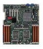
- Asus Z8NR-D12 | User Manual - Page 1
Z8NR-D12 Motherboard - Asus Z8NR-D12 | User Manual - Page 2
Product warranty or service will not be extended if: (1) the product is repaired, modified or altered, unless such repair, modification of alteration is authorized in writing by ASUS; or (2) the serial number of the product is defaced or missing. ASUS PROVIDES THIS MANUAL "AS IS" WITHOUT WARRANTY - Asus Z8NR-D12 | User Manual - Page 3
Safety information viii About this guide ix Z8NR-D12 specifications summary xi Chapter 1: Product introduction 1.1 Welcome 1-1 1.2 Package contents 1-1 1.3 Serial number label 1-2 1.4 Special features 1-2 1.4.1 Product highlights 1-2 1.4.2 Innovative ASUS features 1-4 Chapter 2: Hardware - Asus Z8NR-D12 | User Manual - Page 4
down function 3-2 3.2.2 Using the dual function power switch 3-2 Chapter 4 BIOS setup 4.1 Managing and updating your BIOS 4-1 4.1.1 AFUDOS utility 4-1 4.1.2 ASUS CrashFree BIOS 3 utility 4-3 4.2 BIOS setup program 4-4 4.2.1 BIOS menu screen 4-5 4.2.2 Menu bar 4-5 4.2.3 Navigation - Asus Z8NR-D12 | User Manual - Page 5
CPU Configuration 4-13 4.4.2 Chipset Configuration 4-16 4.4.3 Legacy Device Configuration 4-20 4.4.4 USB Configuration 4-20 4.4.5 PCIPnP 4-21 4.4.6 Power RAID controller selection 5-2 5.1.4 Setting the RAID item in BIOS 5-2 5.2 LSI Software RAID Configuration Utility 5-3 5.2.1 Creating a - Asus Z8NR-D12 | User Manual - Page 6
6-16 6.5 Management applications and utilities installation 6-18 6.5.1 Running the support DVD 6-18 6.5.2 Drivers menu 6-18 6.5.3 Utilities menu 6-19 6.5.4 Make disk menu 6-19 6.5.5 Contact information 6-19 Appendix: Reference information A.1 Z8NR-D12 model block diagram A-1 vi - Asus Z8NR-D12 | User Manual - Page 7
may cause undesired operation. This equipment has been tested and found to comply with the limits for a used in accordance with manufacturer' s instructions, may cause harmful interference to radio by turning the equipment off and on, the user is encouraged to try to correct the interference by - Asus Z8NR-D12 | User Manual - Page 8
are using, contact your local power company. • If the power supply is broken, do not try to fix it by yourself. Contact a qualified service technician or your retailer. Operation safety • Before installing the motherboard and adding devices on it, carefully read all the manuals that came with the - Asus Z8NR-D12 | User Manual - Page 9
when installing system components. It includes description of the switches, jumpers, and connectors on the motherboard. • Chapter 3: Powering up This chapter describes the power up sequence and ways of shutting down the system. • Chapter 4: BIOS setup This chapter tells how to change system settings - Asus Z8NR-D12 | User Manual - Page 10
manual. DANGER/WARNING: Information to prevent injury to yourself when trying to complete a task. CAUTION: Information to prevent damage to the components when trying to complete a task. IMPORTANT: Instructions as shown, then supply the required item or value enclosed in brackets. - Asus Z8NR-D12 | User Manual - Page 11
Type Expansion Slots (follow SSI Location #) Memory Size Total PCI/PCI-X/PCI-E Slots Slot Location 1 Slot Location 3 Slot Location 4 Slot Location 5 Slot Location 6 Storage Additional Slot SATA Controller SAS Controller Z8NR-D12 2 x Socket LGA1366 Quad-Core Intel® Xeon® W5500 Series (130W - Asus Z8NR-D12 | User Manual - Page 12
Band Remote Management CPU Temperature FAN RPM 2 x Intel® 82574L + 1 x Management LAN Aspeed AST2050 8MB 24-pin ATX power connector + 2 x 8-pin ATX 12V power connector 3 (support 4 USB ports and 1 internal Type A USB connector) 8 * 4Pin (With PWM control) 2 1 2 1 1 2 1 2 1 ASWM Optional ASMB4-iKVM - Asus Z8NR-D12 | User Manual - Page 13
This chapter describes the motherboard features and the new technologies it supports. 1Product introduction - Asus Z8NR-D12 | User Manual - Page 14
Chapter summary 1 1.1 Welcome 1-1 1.2 Package contents 1-1 1.3 Serial number label 1-2 1.4 Special features 1-2 ASUS Z8NR-D12 - Asus Z8NR-D12 | User Manual - Page 15
Support CD Documentation User Guide Packing Qty. Standard Gift Box Pack Standard Bulk Pack Z8NR-D12 Z8NR-D12 6 -- 1 -- 1 1 1 1 1 1 1 pcs per carton 10 pcs per carton Optional items PIKE 1064E PIKE 1068E PIKE 1078 PIKE 6480 ASMB4-iKVM ASUS MIO audio card Description LSI 4 port SAS - Asus Z8NR-D12 | User Manual - Page 16
number of the product, ASUS Technical Support team members can then offer a quicker and satisfying solution to your problems. Z8NR-D12 xxM0Axxxxxxx Made in China 合格 1.4 Special features 1.4.1 Product highlights Latest processor technology This motherboard supports the latest Intel Xeon 5500 - Asus Z8NR-D12 | User Manual - Page 17
Intel SpeedStep Technology (EIST) intelligently manages the CPU resources by automatically adjusting the CPU voltage and core frequency depending on the CPU loading and system speed or power requirement. Serial ATA II technology The motherboard supports the Serial ATA II 3 Gb/s technology through - Asus Z8NR-D12 | User Manual - Page 18
levels to ensure stable supply of current for critical components. 1.4.2 Innovative ASUS features ASUS EPU With current trends leaning towards power efficiency, the Z8NR-D12 is equipped with the ASUS exclusive EPU technology to provide total system power saving by detecting current CPU loadings and - Asus Z8NR-D12 | User Manual - Page 19
This chapter lists the hardware setup procedures that you have to perform when installing system components. It includes description of the jumpers and connectors on the motherboard. 2 Hardware information - Asus Z8NR-D12 | User Manual - Page 20
Chapter summary 2 2.1 Before you proceed 2-1 2.2 Motherboard overview 2-2 2.3 Central Processing Unit (CPU 2-6 2.4 System memory 2-11 2.5 Expansion slots 2-14 2.6 Jumpers 2-18 2.7 Connectors 2-23 ASUS Z8NR-D12 - Asus Z8NR-D12 | User Manual - Page 21
or in the bag that came with the component. • Before you install or remove any component, ensure that the power supply is switched off or the power cord is detached from the power supply. Failure to do so may cause severe damage to the motherboard, peripherals, and/or components. ASUS Z8NR-D12 2-1 - Asus Z8NR-D12 | User Manual - Page 22
SSI EEB compliant chassis. Ensure to unplug the chassis power cord before installing or removing the motherboard. Failure to do so can cause you physical injury and damage motherboard components! 2.2.1 Placement direction When installing the motherboard, ensure that you place it into the chassis in - Asus Z8NR-D12 | User Manual - Page 23
2.2.3 Motherboard layouts ASUS Z8NR-D12 2-3 - Asus Z8NR-D12 | User Manual - Page 24
contents Slots / Sockets 1. CPU sockets 2. DDR3 DIMM sockets utility selection (3-pin RAID_SEL1) 6. Force BIOS recovery setting (3-pin RECOVERY1) 7. Fan panel connectors 1. PS/2 mouse port (green) 2. RJ-45 port for iKVM 3. PS/2 keyboard port (purple) 4. USB 2.0 ports 1 and 2 - Asus Z8NR-D12 | User Manual - Page 25
SATA1-4 [red], SATA5-6 [black]) 3. SAS connectors (7-pin SAS1-4 [red], SAS5-8 [ CPU and system fan connectors (4-pin CPU_FAN1/2, REAR_FAN1/2, FRNT_FAN1/2/3/4) 9. Serial port connectors (10-1 pin COM2) 10. Power supply SMBus connector (5-pin PSUSMB1) 11. SSI power 2-31 ASUS Z8NR-D12 2-5 - Asus Z8NR-D12 | User Manual - Page 26
(CPU) The motherboard comes with two surface mount LGA1366 sockets designed for the Intel® Xeon® Dual/Quad Core processor. • Your boxed Intel® Xeon® LGA1366 processor package should come with installation instructions for the CPU and heatsink. If the instructions in this section do not match the CPU - Asus Z8NR-D12 | User Manual - Page 27
PnP cap unless you are installing a CPU. Retention tab A B Load lever 3. Lift the load lever in the direction of the arrow to a 135º angle. 4. Lift the load plate with your thumb and forefinger to a 100º angle. Load plate 4 3 5. Remove the PnP cap from the CPU socket. PnP cap ASUS Z8NR-D12 2-7 - Asus Z8NR-D12 | User Manual - Page 28
socket, and then fit the socket alignment key into the CPU notch. The CPU fits in only one correct orientation. DO NOT force the CPU into the socket to prevent bending the connectors on the socket and damaging the CPU! CPU notch Alignment key Gold triangle mark 7. Apply some Thermal Interface - Asus Z8NR-D12 | User Manual - Page 29
installation. To install the CPU heatsink and fan: 1. Place the heatsink on top of the installed CPU, ensuring that the four screws on the heatsink align with the nuts on the support plate. 2. Use a Phillips screwdriver to tighten the four heatsink screws in a diagonal sequence. ASUS Z8NR-D12 2-9 - Asus Z8NR-D12 | User Manual - Page 30
4‑pin fan connector. FAN connector DO NOT forget to connect the CPU fan cable! Hardware monitoring errors may occur if you fail to plug this connector. 4. Repeat steps 1 to 3 to install the other heatsink if you have installed a second CPU, then connect the fan cable to the nearest 4‑pin fan - Asus Z8NR-D12 | User Manual - Page 31
DIMM_F1 Populated Populated Populated DIMM_F2 Populated Due to Intel CPU spec definition, the system will not boot if only one DIMM is installed in DIMM slot A2, B2, or C2 for CPU1, or D2, E2 or F2 for CPU2. Follow the table above for recommended memory configuration. ASUS Z8NR-D12 2-11 - Asus Z8NR-D12 | User Manual - Page 32
4GB or more memory on the motherboard, the actual usable memory for the OS can be about 3GB or less. For effective use of memory, we recommend that you install a 64-bit Windows OS when having 4GB or more memory installed on the motherboard. • This motherboard does not support memory modules made up - Asus Z8NR-D12 | User Manual - Page 33
DIMM. 2 1. Simultaneously press the retaining clips outward to unlock the DIMM. 1 1 DIMM notch Support the DIMM lightly with your fingers when pressing the retaining clips. The DIMM might get damaged when it flips out with extra force. 2. Remove the DIMM from the socket. ASUS Z8NR-D12 2-13 - Asus Z8NR-D12 | User Manual - Page 34
support. Ensure to unplug the power cord before adding or removing expansion cards. Failure to do so may cause you physical injury and damage motherboard 1. Turn on the system and change the necessary BIOS settings, if any. See Chapter 4 for information on BIOS setup. 2. Assign an IRQ to the card. - Asus Z8NR-D12 | User Manual - Page 35
Mouse Port 13 8 Numeric Data Processor 14* 9 Primary IDE Channel 15* 10 Secondary IDE Channel * These IRQs are usually available for ISA or PCI devices. ASUS Z8NR-D12 2-15 - Asus Z8NR-D12 | User Manual - Page 36
the 5500 IOH. This slot supports VGA cards and various server class high performance add-on cards. The slot switches to x8 link automatically if the PIKE slot allows you to choose and change your preferred SAS solution easily. Install an optional ASUS PIKE RAID card based on your needs. PCI slot - Asus Z8NR-D12 | User Manual - Page 37
. Ensure that it is completely seated on the PIKE RAID card slot. 2.5.9 Installing i Button Follow the steps below to install an optional i Button on your motherboard. 1. Locate the I Button slot on the motherboard. 2. Snap the I Button in place. ASUS Z8NR-D12 2-17 - Asus Z8NR-D12 | User Manual - Page 38
clear the CMOS memory of date, time, and system setup parameters by erasing the CMOS RTC RAM data. The onboard button cell battery powers the RAM data pins 1-2. 3. Plug the power cord and turn ON the computer. 4. Hold down the key during the boot process and enter BIOS setup to re-enter data. - Asus Z8NR-D12 | User Manual - Page 39
, LAN_SW2) These jumpers allow you to enable or disable the onboard Intel® WG82574L Gigabit LAN1/2 controller. Set to pins 1-2 to activate the Gigabit LAN feature. ASUS Z8NR-D12 2-19 - Asus Z8NR-D12 | User Manual - Page 40
if you install a PIKE RAID card to the motherboard and want to use the LSI Logic MPT Setup on pins 2-3 to create the LSI Mega RAID 5 by supported Intel® ICH10R SATA controller. • LSI Logic MPT Setup Utility iBTN to I_BTN1 slot and install an optional ASUS PIKE RAID card. 5. RAID configuration utility - Asus Z8NR-D12 | User Manual - Page 41
.ROM) and the AFUDOS.EXE utility. 2. Set the jumper to pins 2-3. 3. Insert the floppy disk then turn on the system to update the BIOS. 4. Shut down the system. 5. Set the jumper back to pins 1-2. 6. Turn on the system. Use the AFUDOS uitility version 2.38 to flash the BIOS. ASUS Z8NR-D12 2-21 - Asus Z8NR-D12 | User Manual - Page 42
Fan control setting (3-pin FAN_SEL1) This jumper allows you to switch for fan pin selection. Set to pins 1-2 when using 4- settings. Place the jumper caps on pins 1-2 if you want to control DDR3 voltage by BIOS settings (default). Place the jumper caps on pins 2-3 to force the DDR3 DIMMs to run - Asus Z8NR-D12 | User Manual - Page 43
mouse port (green). This port is for a PS/2 mouse. 2. RJ-45 port for iKVM. This RJ-45 port functions only when you install the ASUS ASMB4 iKVM management card. 3. PS/2 keyboard port (purple). This port is for a PS/2 keyboard. 1 Gbps connection ACT/LINK SPEED LED LED LAN port ASUS Z8NR-D12 2-23 - Asus Z8NR-D12 | User Manual - Page 44
connectors, controlled by southbridge ICH10R, are for the Serial ATA signal cables for Serial ATA hard disk drives. Ensure to install the ICH10R RAID driver from the support DVD during OS installation after configuring a RAID set using the SATA connectors. 2-24 Chapter 2: Hardware information - Asus Z8NR-D12 | User Manual - Page 45
card. • Ensure to install the PIKE RAID driver during OS installation after configuring a RAID set using the SAS connectors. 4. Hard disk activity LED connector (4-pin HDLED1) This connector is used to connect to a hard disk drive active LED connector on the SCSI or RAID card. ASUS Z8NR-D12 2-25 - Asus Z8NR-D12 | User Manual - Page 46
LSI embedded SATA RAID or Intel Matrix RAID. 6. Serial General Purpose Input/Output connectors (6-1 pin SGPIO2/3) These connector is used for the SAS chip SIO interface that controls the LED pattern generation, device information and general purpose data. These connectors functions only when you - Asus Z8NR-D12 | User Manual - Page 47
with USB 2.0 specification that supports up to 480 Mbps connection speed. The USB port module is purchased separately. 8. CPU and system fan connectors (4-pin the system may damage the motherboard components. These are not jumpers! DO NOT place jumper caps on the fan connectors! ASUS Z8NR-D12 2-27 - Asus Z8NR-D12 | User Manual - Page 48
the module to a slot opening at the back of the system chassis. The serial port module is purchased separately. 10. Power supply SMBus connector (5-pin PSUSMB1) This connector is for the power supply SMB cable, if your power supply supports the SMBus function. 2-28 Chapter 2: Hardware information - Asus Z8NR-D12 | User Manual - Page 49
with a higher power rating if you intend to install additional devices. 12. Baseboard Management Controller (BMC) connector (14-pin BMC_FW1) This is an interface used to plug in an ASMB4-SOL or ASMB4-iKVM management device. The ASMB4 management device is purchased separately. ASUS Z8NR-D12 2-29 - Asus Z8NR-D12 | User Manual - Page 50
power, and blinks when the system is in sleep mode. 2. Message LED (2-pin MLED) This 2-pin connector is for the message LED cable that connects to the front message LED. The message or soft-off mode depending on the BIOS settings. Pressing the power switch for more than four seconds while the system - Asus Z8NR-D12 | User Manual - Page 51
[black]) This connector is for additional front panel features including front panel SMB, locator LED and switch, chassis intrusion, and LAN LEDs. 1. Front panel SMB (6-1 pin FPSMB) These leads connect the the front panel. This button queries the state of the system locator. ASUS Z8NR-D12 2-31 - Asus Z8NR-D12 | User Manual - Page 52
2-32 Chapter 2: Hardware information - Asus Z8NR-D12 | User Manual - Page 53
This chapter describes the power up Powerin3g up sequence, and ways of shutting down the system. - Asus Z8NR-D12 | User Manual - Page 54
Chapter summary 3 3.1 Starting up for the first time 3-1 3.2 Turning off the computer 3-2 ASUS Z8NR-D12 - Asus Z8NR-D12 | User Manual - Page 55
beep followed by four short beeps Description VGA detected Quick boot set to disabled No keyboard detected No memory detected No VGA detected Hardware component failure 7. At power on, hold down the key to enter the BIOS Setup. Follow the instructions in Chapter 4. ASUS Z8NR-D12 3-1 - Asus Z8NR-D12 | User Manual - Page 56
3. The power supply should turn off after Windows® shuts down. 3.2.2 Using the dual function power switch While the system is ON, pressing the power switch for less than four seconds puts the system to sleep mode or to soft-off mode, depending on the BIOS setting. Pressing the power switch for more - Asus Z8NR-D12 | User Manual - Page 57
This chapter tells how to change the system settings through the BIOS Setup menus. Detailed descriptions of the BIOS parameters are also provided. 4 BIOS setup - Asus Z8NR-D12 | User Manual - Page 58
Chapter summary 4 4.1 Managing and updating your BIOS 4-1 4.2 BIOS setup program 4-4 4.3 Main menu 4-7 4.4 Advanced menu 4-13 4.5 Server menu 4-27 4.6 Power menu 4-29 4.7 Exit menu 4-34 ASUS Z8NR-D12 - Asus Z8NR-D12 | User Manual - Page 59
/oOLDBIOS1.rom AMI Firmware Update Utility - Version 1.19(ASUS V2.07(03.11.24BB)) Copyright (C) 2002 American Megatrends, Inc. All rights reserved. Reading flash ..... done Write to file...... ok A:\> The utility returns to the DOS prompt after copying the current BIOS file. ASUS Z8NR-D12 4-1 - Asus Z8NR-D12 | User Manual - Page 60
the BIOS update process is completed. Reboot the system from the hard disk drive. A:\>afudos /iZ8NRD12.ROM AMI Firmware Update Utility - Version 1.19(ASUS V2.07(03.11.24BB)) Copyright (C) 2002 American Megatrends, Inc. All rights reserved. WARNING!! Do not turn off power during flash BIOS Reading - Asus Z8NR-D12 | User Manual - Page 61
the updating process. DO NOT shut down or reset the system while recovering the BIOS! Doing so would cause system boot failure! The recovered BIOS may not be the latest BIOS version for this motherboard. Visit the ASUS website (www.asus.com) to download the latest BIOS file. ASUS Z8NR-D12 4-3 - Asus Z8NR-D12 | User Manual - Page 62
setup program This motherboard supports a programmable firmware chip that you can update using the provided utility described in section 4.1 Managing and updating your BIOS. Use the BIOS Setup program when you are installing a motherboard, reconfiguring your system, or prompted to "Run Setup." This - Asus Z8NR-D12 | User Manual - Page 63
screen Menu items Menu bar Configuration fields General help Main Advanced BIOS SETUP UTILITY Server Boot Exit System Time [13:44:30] System Date [Tue, 11/04/2008] Legacy Diskette A [1.44M the settings. Some of the navigation keys differ from one screen to another. ASUS Z8NR-D12 4-5 - Asus Z8NR-D12 | User Manual - Page 64
shows the Main menu items. The other items (Advanced, Power, Boot, and Exit) on the menu bar have their respective item. You cannot select an item that is not user-configurable. A configurable field is enclosed in brackets, screen. Advanced BIOS SETUP UTILITY CPU Bridge Chipset Configuration USB - Asus Z8NR-D12 | User Manual - Page 65
basic system information. Refer to section 4.2.1 BIOS menu screen for information on the menu screen items and how to navigate through them. Main Advanced BIOS SETUP UTILITY Server Boot Exit System Time [ MB, 5.25 in.] [720 KB, 3.5 in.] [1.44 MB, 3.5 in] [2.88 MB, 3.5 in] ASUS Z8NR-D12 4-7 - Asus Z8NR-D12 | User Manual - Page 66
information. Main BIOS SETUP UTILITY SATA 1 Device :Hard Disk Vendor :ST3160812AS Size :160.0GB LBA Mode :Supported Block Mode:16Sectors , Async DMA, Ultra DMA, and S.M.A.R.T. monitoring). These values are not user-configurable. These items show N/A if no IDE device is installed in the - Asus Z8NR-D12 | User Manual - Page 67
Monitoring, Analysis, and Reporting Technology. Configuration options: [Auto] [Disabled] [Enabled] 32Bit Data Transfer [Enabled] Enables or disables 32-bit data transfer. Configuration options: [Disabled] [Enabled] ASUS Z8NR-D12 4-9 - Asus Z8NR-D12 | User Manual - Page 68
then press if you wish to configure the item. Main BIOS SETUP UTILITY IDE Configuration SATA Configuration Configure SATA as [Compatible] [IDE this item to [AHCI]. The AHCI allows the onboard storage driver to enable advanced Serial ATA features that increases storage performance on - Asus Z8NR-D12 | User Manual - Page 69
XXXX] Displays the status of auto-detection of SATA devices. Main SATA Port1 Device :Not Detected BIOS SETUP UTILITY SATA Port0 [Auto] SMART Monitoring [Enabled] Select the type of device connected to Reporting Technology. Configuration options: [Disabled] [Enabled] ASUS Z8NR-D12 4-11 - Asus Z8NR-D12 | User Manual - Page 70
Displays the auto-detected CPU specification. System Memory Displays the auto-detected system memory. System Memory Information Displays system memory information. Main AMIBIOS CPU1 Memory Configuration CPU2 Memory Configuration BIOS SETUP UTILITY CPU1/2 Memory Configuration Allows you to - Asus Z8NR-D12 | User Manual - Page 71
Main Advanced Server BIOS SETUP UTILITY Boot Exit CPU Configuration Chipset Configuration Legacy Device Configuration USB Configuration PCIPnP Configuration Power On Configuration [Enabled] C3 Auto Demotion [Enabled] v02.61 (C)Copyright 1985-2008, American Megatrends, Inc. ASUS Z8NR-D12 4-13 - Asus Z8NR-D12 | User Manual - Page 72
CMOS Setting [Auto] Allows you to adjust the ratio between CPU Core Clock and BCLK Frequency. Use the and keys to adjust the value. Configuration options: [Auto] [12.0] [13.0] [14.0] [15.0] [16.0] [17.0] [18.0] [19.0] [20.0] C1E Support [Enabled] Allows you to enable or disable Enhanced Halt - Asus Z8NR-D12 | User Manual - Page 73
detect the C-State mode supported by your CPU. Configuration options: [Auto] [C1] [C3] [C6] [C7] C1 Auto Demotion [Enabled] When enabled, CPU will conditionally demote C3/C6/C7 requests to C1 based on on-core auto-demote information. Configuration options: [Disabled] [Enabled] ASUS Z8NR-D12 4-15 - Asus Z8NR-D12 | User Manual - Page 74
Exit v02.61 (C)Copyright 1985-2008, American Megatrends, Inc. CPU Bridge Chipset Configuration Advanced BIOS SETUP UTILITY CPU Bridge Chipset Configuration CPU REVISION :B0 Current CSI Frequency :6.400GT Current Memory Frequency :1066 Mhz CSI Links Speed CSI Frequency CSI Isochronous - Asus Z8NR-D12 | User Manual - Page 75
Disabled] Configuration options: [Disabled] [Enabled] Memory Frequency [Auto] You may allow the system to detect DDR3 memory frequency via SPD or designate a specific frequency. Configuration options: [Disabled] [Enabled] NUMA AWare [Auto] Configuration options: [Disabled] [Auto] ASUS Z8NR-D12 4-17 - Asus Z8NR-D12 | User Manual - Page 76
or disable the Crystal Beach / DMA function. Configuration options: [Disabled] [Enabled] South Bridge Chipset Configuration Advanced BIOS SETUP UTILITY CPU Bridge Chipset Configuration USB Functions USB Port Configure USB 2.0 Controller HDA Controller [7 USB Ports] [6+6 USB Ports - Asus Z8NR-D12 | User Manual - Page 77
] [1 to 2 seconds] Intel VT-d Configuration Advanced BIOS SETUP UTILITY Intel VT-d [Disabled] Options Disabled Enabled Intel VT-d [Disabled] Allows you to enable or disable the Intel Virtualization Technology for Directed I/O. Configuration options: [Disabled] [Enabled] ASUS Z8NR-D12 4-19 - Asus Z8NR-D12 | User Manual - Page 78
- 2.24.3-13.4 USB Devices Enabled : None Legacy USB Support USB 2.0 Controller Mode BIOS EHCI Hand-Off Hotplug USB FDD Support [Enabled] [HiSpeed] [Enabled] [Auto] Enables support for legacy USB. AUTO option disables legacy support if no USB devices are connected. The following item - Asus Z8NR-D12 | User Manual - Page 79
or disables the BIOS EHCI hand-off support. Configuration options: [Disabled] [Enabled] Hotplug USB FDD Support [Auto] Allows you to configure the Hotplug USB FDD support. Configuration options: to configure the onboard LAN1/2 boot mode. Configuration: [Disabled] [PXE] [iSCSI] ASUS Z8NR-D12 4-21 - Asus Z8NR-D12 | User Manual - Page 80
On Configuration Advanced BIOS SETUP UTILITY APM Configuration Restore on AC Power Loss [Last State] Resume On Ring [Disabled] Resume On PME#(Wake On LAN) [Disabled] Resume On RTC Alarm [Disabled] Options Power Off Power On Last State ←→ Select Screen ↑↓ Select Item +- Change Option F1 - Asus Z8NR-D12 | User Manual - Page 81
Log Configuration Advanced Event Logging details View Event Log Mark all events as read Clear Event Log BIOS SETUP UTILITY View all unread events on the Event log. ←→ Select Screen ↑↓ Select Item the key to clear all system events. Select [Ok] to confirm the change. ASUS Z8NR-D12 4-23 - Asus Z8NR-D12 | User Manual - Page 82
Advanced BIOS SETUP xxxºC/xxxºF] The onboard hardware monitor automatically detects and displays the CPU temperatures. Select [Ignored] if you do not wish to connected to the motherboard, the field shows [N/A]. Smart Fan Control [Generic Mode] Allows you to configure the ASUS Smart Fan feature - Asus Z8NR-D12 | User Manual - Page 83
] [Enabled] Chipset ACPI Configuration Advanced BIOS SETUP UTILITY South Bridge ACPI Configuration Energy Lake Feature APIC ACPI SCI IRQ USB Device Wakeup From S3/S4 High Performance Event Timer [Disabled] [Disabled] [Disabled] [Disabled] Options Enabled Disabled ASUS Z8NR-D12 4-25 - Asus Z8NR-D12 | User Manual - Page 84
you to enable or disable the Windows Hardware Error Architecture (WHEA) support. Configuration options: [Disabled] [Enabled] 4.4.10 PCI Express Configuration Advanced BIOS SETUP UTILITY PCI Express Configuration Active State Power-Management [Disabled] Enable/Disable PCI Express L0s and L1 link - Asus Z8NR-D12 | User Manual - Page 85
item then press to display the configuration options. Server BIOS SETUP UTILITY Configure Remote Access type and parameters Remote Access [Enabled Address. IRQ [2F8h, 3] This item is not user-configurable and changes with the configuration of Serial port number. ASUS Z8NR-D12 4-27 - Asus Z8NR-D12 | User Manual - Page 86
after the BIOS Power-On Self-Test (POST). Some operating system may not work when set to [Always]. Configuration options: [Disabled] [Boot Loader] [Always] Terminal Type [VT-UTF8] Allows you to select the target terminal type. Configuration options: [ANSI] [VT100] [VT-UTF8] VT-UTF8 Combo Key Support - Asus Z8NR-D12 | User Manual - Page 87
ESC Exit v02.61 (C)Copyright 1985-2008, American Megatrends, Inc. 4.6.1 Boot Device Priority BIOS SETUP UTILITY Boot Boot Device Priority 1st Boot Device 2nd Boot Device 3rd Boot Device 4th Boot installed in the system. Configuration options: [xxxxx Drive] [Disabled] ASUS Z8NR-D12 4-29 - Asus Z8NR-D12 | User Manual - Page 88
appears on the screen depends on the number of devices installed in the system. Configuration options: [xxxxx Drive] [Disabled] 4.6.3 Removable Drives BIOS SETUP UTILITY Boot Removable Drives 1st Drive [1st FLOPPY DRIVE] Specifies the boot sequence from the available devices. +F1 F10 ESC - Asus Z8NR-D12 | User Manual - Page 89
], the system displays the message "Press DEL to run Setup" during POST. Configuration options: [Disabled] [Enabled] Interrupt 19 Capture [Enabled] When set to [Enabled], this function allows the option ROMs to trap Interrupt 19. Configuration options: [Disabled] [Enabled] ASUS Z8NR-D12 4-31 - Asus Z8NR-D12 | User Manual - Page 90
the supervisor password, follow the same steps as in setting a user password. To clear the supervisor password, select the Change Supervisor Password then press . The message "Password Uninstalled" appears. If you forget your BIOS password, you can clear it by erasing the CMOS Real Time - Asus Z8NR-D12 | User Manual - Page 91
in setting a user password. Password Check [Setup] When set to [Setup], BIOS checks for user password when accessing the Setup utility. When set to [Always], BIOS checks for user password both when accessing Setup and booting the system. Configuration options: [Setup] [Always] ASUS Z8NR-D12 4-33 - Asus Z8NR-D12 | User Manual - Page 92
the Setup program without saving your changes, the program prompts you with a message asking if you want to save your changes before exiting. Press - Asus Z8NR-D12 | User Manual - Page 93
This chapter provides instructions for setting up, creating, and configuring configurRa5tAioIDn RAID sets using the available utilities. - Asus Z8NR-D12 | User Manual - Page 94
Chapter summary 5 5.1 Setting up RAID 5-1 5.2 LSI Software RAID Configuration Utility 5-3 5.3 Intel® Matrix Storage Manager Option ROM Utility 5-23 ASUS Z8NR-D12 - Asus Z8NR-D12 | User Manual - Page 95
a minimum of three identical hard disk drives for this setup. 5.1.2 Installing hard disk drives The motherboard supports SATA hard disk drives for RAID set configuration. For optimal performance, install identical drives of the same model and capacity when creating a disk array. ASUS Z8NR-D12 5-1 - Asus Z8NR-D12 | User Manual - Page 96
configuration utility selection on page 2-20 for details. 5.1.4 Setting the RAID item in BIOS You must enable the RAID function in the BIOS Setup before creating RAID set(s) using SATA HDDs. To do this: 1. Enter the BIOS Setup during POST. 2. Go to the Main menu > IDE Configuration, and then press - Asus Z8NR-D12 | User Manual - Page 97
connectors supported by the motherboard drive has to be manually adjusted. Otherwise, BIOS Version A.08.09161344R Management Menu Configure Initialize Objects Rebuild Check Consistency Configure VD(s) Use Cursor Keys to Navigate Between Items And Press Enter To Select An Option ASUS Z8NR-D12 - Asus Z8NR-D12 | User Manual - Page 98
, the virtual drive parameters are set automatically. In New Configuration, you manually set the virtual drive parameters. Using Easy Configuration To create a RAID RAID Configuration Utility Ver A.60 Jul 30, 2008 BIOS Version A.08.09161344R Configuration Menu Easy Configuration Management - Asus Z8NR-D12 | User Manual - Page 99
is the drive number. LSI Software RAID Configuration Utility Ver A.60 Jul 30, 2008 BIOS Version A.08.09161344R Easy Configuration - ARRAY SELECTION MENU Management Menu Configure Initialize Objects Rebuild Keys, SPACE-(De)Select F2-ChIdInfo F3-SlotInfo F10-Configure Esc-Quit ASUS Z8NR-D12 5-5 - Asus Z8NR-D12 | User Manual - Page 100
RAID level from the menu, and then press . LSI Software RAID Configuration Utility Ver A.60 Jul 30, 2008 BIOS VVierrtsuailonDrivAe.(0s8).0C9on1f6ig1u3r4e4dR LD RAIEDasy CoSnifizgeuratio#nSt-riApReRsAY SELSEtCrTiIpOSNzMENUStatus 0 1 77247MB 2 64 KB ONLINE Management Menu Configure PORT - Asus Z8NR-D12 | User Manual - Page 101
Accept SPAN = NO Accept This VD Configuration And Go To Next VD Cursor Keys, SPACE-(De)Select F2-ChIdInfo F3-SlotInfo F10-Configure Esc-Quit ASUS Z8NR-D12 5-7 - Asus Z8NR-D12 | User Manual - Page 102
, select Yes from the menu, and then press . LSI Software RAID Configuration Utility Ver A.60 Jul 30, 2008 BIOS Version A.08.09161344R Configuration Menu Easy Configuration Management MNeenwu Configuration Configure View/Add Configuration Save Configuration? Yes No Initialize Clear - Asus Z8NR-D12 | User Manual - Page 103
Between Items And Press Enter To Select An Option 5. Follow step 8 to 12 of the previous section: Using Easy Configuration to create the RAID set. ASUS Z8NR-D12 5-9 - Asus Z8NR-D12 | User Manual - Page 104
A[X]-[Y], where X is the array number, and Y is the drive number. LSI Software RAID Configuration Utility Ver A.60 Jul 30, 2008 BIOS Version A.08.09161344R View/Add Configuration - ARRAY SELECTION MENU Management Menu Configure Initialize Objects Rebuild Check Consistency PORT # 0 ONLIN A00-00 - Asus Z8NR-D12 | User Manual - Page 105
, 2008 BIOS Version A.08.09161344R Virtual Drive(s) Configured Management Menu LD RAID Size #Stripes StripSz Status Configure Initialize 0 1 151634MB 2 64 KB ONLINE Objects Rebuild Check Consistency Virtual Drives Virtual Drive 0 Select VD SPACE-(De)Select, F10-Initialize ASUS Z8NR-D12 - Asus Z8NR-D12 | User Manual - Page 106
, select Yes from the Initialize? dialog box, and then press . LSI Software RAID Configuration Utility Ver A.60 Jul 30, 2008 BIOS Version A.08.09161344R Virtual Drive(s) Configured Management Menu LD RAID Size #Stripes StripSz Status Configure 0 10 154494MB 4 64 KB ONLINE Initialize - Asus Z8NR-D12 | User Manual - Page 107
Jul 30, 2008 BIOS Version A.08.09161344R BIOS Version A.08.09161344R Vitual Drive(1) Virtual Drive 0 Objects Management MAednaupter Configure Virtual Drive Initialize Physical Drive Objects Rebuild Check Consistency Select VD Press ENTER To Select A VD, To Delete A VD ASUS Z8NR-D12 - Asus Z8NR-D12 | User Manual - Page 108
LSI Software RAID Configuration Utility Ver A.60 Jul 30, 2008 BIOS Version A.08.09161344R Vitual Drive(1) Virtual Drive 0 Objects Management Rebuild Check Consistency Vitual Drive(0) Initialze Check Consistency View/Update Parameters Initilize VD Use Cursor Keys To Navigate Between - Asus Z8NR-D12 | User Manual - Page 109
manually rebuild failed hard disk drives using the Rebuild command in the Management Menu. To rebuild a failed hard disk drive 1. From the Management Menu, select Rebuild, and then press . LSI Software RAID Configuration Utility Ver A.60 Jul 30, 2008 BIOS Virtual Drives ASUS Z8NR-D12 5-15 - Asus Z8NR-D12 | User Manual - Page 110
to rebuild, press . When prompted, press to rebuild the drive. LSI Software RAID Configuration Utility Ver A.60 Jul 30, 2008 BIOS Version A.08.09161344R REBUILD - PHYSICAL DRIVES SELECTION MENU Management Menu PORT # Configure Initialize 0 ONLIN A00-00 Objects Rebuild 1 RBLD A00-01 - Asus Z8NR-D12 | User Manual - Page 111
BIOS Version A.08.09161344R Virtual Drive(s) Configured Management Menu LD RAID Size #Stripes StripSz Status Configure 0 10 154494MB 4 64 KB ONLINE Initialize Objects Rebuild Check Consistency Virtual Drives Virtual Drive 0 Select VD SPACE-(De)Select, F10-Check Consistency ASUS Z8NR-D12 - Asus Z8NR-D12 | User Manual - Page 112
Yes from the Consistency Check? dialog box, and then press . LSI Software RAID Configuration Utility Ver A.60 Jul 30, 2008 BIOS Version A.08.09161344R Virtual Drive(s) Configured Management Menu LD RAID Size #Stripes StripSz Status Configure 0 10 154494MB 4 64 KB ONLINE Initialize - Asus Z8NR-D12 | User Manual - Page 113
prompted, use the arrow keys to select Yes from the dialog box to check the drive. 5. When checking is complete, press any key to continue. ASUS Z8NR-D12 5-19 - Asus Z8NR-D12 | User Manual - Page 114
Configure > Clear Configuration, and then press . LSI Software RAID Configuration Utility Ver A.60 Jul 30, 2008 BIOS Version A.08.09161344R Configuration Menu Easy Configuration Management MNeenwu Configuration Configure View/Add Configuration Initialize Clear Configuration Objects - Asus Z8NR-D12 | User Manual - Page 115
press . LSI Software RAID Configuration Utility Ver A.60 Jul 30, 2008 BIOS Version A.08.09161344R Configuration Menu Easy Configuration Management MNeenwu Configuration Configure View/Add 3. The virtual drive is selected as boot drive. Press any key to continue. ASUS Z8NR-D12 5-21 - Asus Z8NR-D12 | User Manual - Page 116
You may manually enable the RAID controller's WriteCache option after creating a RAID set to improve the data transmission performance. When you enable WriteCache, you may lose data when a power interruption occurs while Utility Ver A.60 Jul 30, 2008 BIOS Version A.08.09161344R Adapter 0 Rebuild - Asus Z8NR-D12 | User Manual - Page 117
the screen allow you to move through the menus and select the menu options. The RAID BIOS setup screens shown in this section are for reference only and may not exactly match the items on your screen. The utility supports maximum four hard disk drives for RAID configuration. ASUS Z8NR-D12 5-23 - Asus Z8NR-D12 | User Manual - Page 118
5.3.1 Creating a RAID set To create a RAID set 1. From the utility main menu, select 1. Create RAID Volume and press . The following screen appears. Intel(R) Matrix Storage Manager option ROM v8.5.0.1030 ICH10R/DO wRAID5 Copyright(C) 2003-08 Intel Corporation. All Rights Reserved. [ - Asus Z8NR-D12 | User Manual - Page 119
maximum allowed capacity. 8. When the Create Volume item is selected, press . The following warning message appears. WARNING: ALL DATA ON SELECTED DISKS WILL BE LOST. Are you sure you want to characters or less. [↑↓]Change [TAB]-Next [ESC]-Previous Menu [ENTER]-Select ASUS Z8NR-D12 5-25 - Asus Z8NR-D12 | User Manual - Page 120
/down arrow key to select a sync option that you want and press . 7. When the Create Volume item is selected, press . The following warning message appears. WARNING: ALL DATA ON SELECTED DISKS WILL BE LOST. Are you sure you want to create this volume? (Y/N): 8. Press to create the - Asus Z8NR-D12 | User Manual - Page 121
down arrow key to select the RAID set you want to delete, and then press . The following warning message appears. [ DELETE VOLUME VERIFICATION ] ALL DATA IN THE VOLUME WILL BE LOST! (This does not apply utility main menu, or press to return to the DELETE VOLUME menu. ASUS Z8NR-D12 5-27 - Asus Z8NR-D12 | User Manual - Page 122
Member Disk Select the disks that should be reset. [↑↓]-Previous/Next [SPACE]-Selects [ENTER]-Selection Complete 2. Use the up/down arrow key to select the RAID set drive(s) you want to reset, and then press to select. 3. Press to reset the RAID set drive(s). A confirmation message - Asus Z8NR-D12 | User Manual - Page 123
- enables master disk if available and disables recovery disk. Actions will result in change from Continuous Update mode to On-Request. [↑↓]-Select [ESC]-Previous Menu [ENTER]-Select 2. Use the up/down > after completing your selection and return to the utility main menu. ASUS Z8NR-D12 5-29 - Asus Z8NR-D12 | User Manual - Page 124
Exiting the Intel® Matrix Storage Manager To exit the utility 1. From the utility main menu, select 5. Exit, and then press . The following warning message appears. [ CONFIRM EXIT ] Are you sure you want to exit? (Y/N): 2. Press to exit or press to return to the utility main menu - Asus Z8NR-D12 | User Manual - Page 125
ST3160812AS 2 ST3160812AS Serial # 9LS0F4HL 3LS0JYL8 Size 149.0GB 149.0GB Type/Status(Vol ID) Member Disk(0) Member Disk(0) Volumes with "Rebuild" status will be rebuilt within the operating system. [↑↓]-Select Rebuilding the RAID with other non-RAID disk on page 5-30. ASUS Z8NR-D12 5-31 - Asus Z8NR-D12 | User Manual - Page 126
at least one of the arrays bootable to boot from the hard disk. 1. Reboot the system and press to enter the BIOS setup utility during POST. 2. Go to the Boot menu and select the option Boot Device Priority. 3. Use up/down arrow keys to select the boot - Asus Z8NR-D12 | User Manual - Page 127
This chapter provides instructions for installing the necessary drivers for different system components. 6Driver installation - Asus Z8NR-D12 | User Manual - Page 128
Chapter summary 6 6.1 RAID driver installation 6-1 6.2 Intel chipset device installation 6-11 6.3 LAN driver installation 6-13 6.4 VGA driver installation 6-16 6.5 Management application and utilities installation 6-18 ASUS Z8NR-D12 - Asus Z8NR-D12 | User Manual - Page 129
RAID Driver ICH10R LSI RAID Driver Write DMI FreeDOS command prompt 5. Use the arrow keys to select the type of RAID driver disk you want to create and press to enter the sub-menu. ICH10R INTEL RAID Driver ICH10R INTEL RAID Driver Windows 32 bit Windows 64 bit Back Exit ASUS Z8NR-D12 6-1 - Asus Z8NR-D12 | User Manual - Page 130
SP2 64 bit Back Exit Write DMI Write DMI RS700-E6-RS4 system RS500-E6-PS4 system Back Exit 6. Locate the RAID driver and place a blank, high-density floppy disk to the floppy disk drive. 7. Press . 8. Follow screen instructions to create the driver disk. 6-2 Chapter 6: Driver installation - Asus Z8NR-D12 | User Manual - Page 131
Insert a blank formatted high-density floppy disk to the floppy disk drive. 2. Decompress the file into the floppy disk from the following path in the support DVD: For LSI Logic Embedded SATA RAID Driver: \Drivers\ICH10R LSI RAID\Driver\makedisk\Linux 3. Eject the floppy disk. ASUS Z8NR-D12 6-3 - Asus Z8NR-D12 | User Manual - Page 132
third party SCSI or RAID driver... 2. Press when the message "Press F6 if you need to install a third party SCSI or RAID driver..." appears at the bottom your system, or you have chosen to manually specify an adapter. Currently, Setup will load support for the following mass storage devices(s): - Asus Z8NR-D12 | User Manual - Page 133
OS installation. Follow screen instructions to continue. To an existing Windows® Server OS To install the RAID controller driver on an existing Windows® RAID controller drivers. When found, click Next to install the drivers. 11. Click Finish after the driver installation is done. ASUS Z8NR-D12 6-5 - Asus Z8NR-D12 | User Manual - Page 134
item should appear. The screen differs based on the controller. 4. Right-click the RAID controller driver item, and then select Properties from the menu. 5. Click the Driver tab, and then click the Driver Details button to display the RAID controller drivers. 6. Click OK when finished. 6-6 Chapter - Asus Z8NR-D12 | User Manual - Page 135
4. Select fd0 using the key when asked to select the driver disk source. Press to move the cursor to OK, then press . Driver Disk Source You have multiple devices which could serve as sources for a driver disk. Which would you like to use? fd0 sDVD0 OK Cancel ASUS Z8NR-D12 6-7 - Asus Z8NR-D12 | User Manual - Page 136
for the RAID card are installed to the system. 6. When asked if you will load additional RAID controller drivers, select No, then press . More Driver Disks? Do you wish to load any more driver disks? Yes No 7. Follow the screen instructions to continue the OS installation. 6-8 Chapter - Asus Z8NR-D12 | User Manual - Page 137
then select Yes from the menu. Press . Boot from Hard Disk Installation Installation--ACPI Disabled Installation--Local APIC Disabled Installation--Safe Settings Rescue System Memory Test Boot Options | Yes No File F1 Help F2 Language F3 1280 x 1024 F4 DVD F5 Driver ASUS Z8NR-D12 6-9 - Asus Z8NR-D12 | User Manual - Page 138
Installation--Local APIC Disabled Installation--Safe Settings Rescue System Memory Test Boot Options | F1 Help F2 Language F3 1280 x 1024 F4 DVD F5 Driver 5. When below screen appears, select the floppy disk drive (fd0) as the driver update medium. Select OK, then press . Please choose the - Asus Z8NR-D12 | User Manual - Page 139
support DVD to the optical drive. The support DVD automatically displays the Drivers menu if Autorun is enabled in your computer. 3. Click the item Intel Chipset Device Software from the menu. 4. The Intel(R) Chipset Device Software window appears. Click Next to start installation. ASUS Z8NR-D12 - Asus Z8NR-D12 | User Manual - Page 140
5. Select Yes to accept the terms of the License Agreement and continue the process. 6. Read the Readme File Information and press Next to continue the installation. 7. After completing the installation, click Finish to complete the setup process. 6-12 Chapter 6: Driver installation - Asus Z8NR-D12 | User Manual - Page 141
, browse the contents of the support DVD to locate the file ASSETUP.EXE from the BIN folder. Doubleclick the ASSETUP.EXE to run the DVD. 3. Click the Intel Network Connections Software to begin installation. 4. Click Install Drivers and Software option to begin installation. ASUS Z8NR-D12 6-13 - Asus Z8NR-D12 | User Manual - Page 142
agreement and click Next to continue. 7. Click the Intel(R) PROSet for Windows Device Manager box, and then click Next to start the installation. 6-14 Chapter 6: Driver installation - Asus Z8NR-D12 | User Manual - Page 143
8. Follow the screen instructions to complete installation. 9. When finished, press Finish to continue. ASUS Z8NR-D12 6-15 - Asus Z8NR-D12 | User Manual - Page 144
Graphics Adapter (VGA) driver. You need to manually install the Aspeed® AST2050 VGA driver on a Windows® Server operating system. To install the Aspeed® AST2050 VGA driver 1. Restart the computer, then log on with Administrator privileges. 2. Insert the motherboard/system support DVD to the optical - Asus Z8NR-D12 | User Manual - Page 145
4. Click Install to update the VGA driver. 5. When the installation completes, click Finish to restart your computer before using the program. ASUS Z8NR-D12 6-17 - Asus Z8NR-D12 | User Manual - Page 146
, and utilities that you can install to avail all motherboard features. The contents of the support DVD are subject to change at any time without notice. Visit the ASUS website (www.asus.com) for updates. 6.5.1 Running the support DVD Place the support DVD to the optical drive. The DVD automatically - Asus Z8NR-D12 | User Manual - Page 147
Make disk menu The Make disk menu contains items to create the Intel ICH10R and LSI MegaRAID driver disks. 6.5.5 Contact information Click the Contact tab to display the ASUS contact information. You can also find this information on the inside front cover of this user guide. ASUS Z8NR-D12 6-19 - Asus Z8NR-D12 | User Manual - Page 148
6-20 Chapter 6: Driver installation - Asus Z8NR-D12 | User Manual - Page 149
This appendix includes additional information that you may refer to when configuring the motherboard. A Reference information - Asus Z8NR-D12 | User Manual - Page 150
Appendix summary A A.1 Z8NR-D12 model block diagram A-1 ASUS Z8NR-D12 - Asus Z8NR-D12 | User Manual - Page 151
A.1 Z8NR-D12 model block diagram ASUS Z8NR-D12 A-1 - Asus Z8NR-D12 | User Manual - Page 152
A-2 Appendix A: Reference information
-
 1
1 -
 2
2 -
 3
3 -
 4
4 -
 5
5 -
 6
6 -
 7
7 -
8
-
9
-
10
-
11
-
12
-
13
-
14
-
15
-
16
-
17
-
18
-
19
-
20
-
21
-
22
-
23
-
24
-
25
-
26
-
27
-
28
-
29
-
30
-
31
-
32
-
33
-
34
-
35
-
36
-
37
-
38
-
39
-
40
-
41
-
42
-
43
-
44
-
45
-
46
-
47
-
48
-
49
-
50
-
51
-
52
-
53
-
54
-
55
-
56
-
57
-
58
-
59
-
60
-
61
-
62
-
63
-
64
-
65
-
66
-
67
-
68
-
69
-
70
-
71
-
72
-
73
-
74
-
75
-
76
-
77
-
78
-
79
-
80
-
81
-
82
-
83
-
84
-
85
-
86
-
87
-
88
-
89
-
90
-
91
-
92
-
93
-
94
-
95
-
96
-
97
-
98
-
99
-
100
-
101
-
102
-
103
-
104
-
105
-
106
-
107
-
108
-
109
-
110
-
111
-
112
-
113
-
114
-
115
-
116
-
117
-
118
-
119
-
120
-
121
-
122
-
123
-
124
-
125
-
126
-
127
-
128
-
129
-
130
-
131
-
132
-
133
-
134
-
135
-
136
-
137
-
138
-
139
-
140
-
141
-
142
-
143
-
144
-
145
-
146
-
147
-
148
-
149
-
150
-
151
-
152
 |
 |

Motherboard
Z8NR-D12