Behringer 130 DUAL VCA Quick Start Guide
Behringer 130 DUAL VCA Manual
 |
View all Behringer 130 DUAL VCA manuals
Add to My Manuals
Save this manual to your list of manuals |
Behringer 130 DUAL VCA manual content summary:
- Behringer 130 DUAL VCA | Quick Start Guide - Page 1
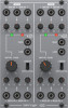
Quick Start Guide 130 DUAL VCA Legendary Analog Dual VCA Module for Eurorack Controls Power Connection (1) (2) (3) (4) (5) (6) (7) (1) SIG IN input jacks accept audio signals over cables with 3.5 mm TS connectors. (2) SIG IN knobs control the gain level at the SIG IN inputs. (3) VCA OUT (HIGH/LOW) - Behringer 130 DUAL VCA | Quick Start Guide - Page 2
Signal Connections Signal in Impedance Maximum input level VCA out high / low High output Impedance Low , Klark Teknik, Lab Gruppen, Lake, Tannoy, Turbosound, TC Electronic, TC Helicon, Behringer, Bugera, Auratone and Coolaudio are trademarks or registered trademarks of Music Tribe Global Brands
-
 1
1 -
 2
2
 |
 |

Quick Start Guide
130 DUAL VCA
Legendary Analog Dual VCA
Module for Eurorack
Controls
(1)
SIG IN
input jacks accept audio signals over cables with
3.5 mm TS connectors.
(2)
SIG IN
knobs control the gain level at the SIG IN inputs.
(3)
VCA OUT (HIGH/LOW)
outputs connect to the inputs
of external equipment over cables with 3.5 mm TRS
connectors. (Note that these connections are both
mono and not left/right). The HIGH mono output can be
connected to the line-level inputs of mixers, keyboard
amplifiers or powered speakers. The LOW output is an
instrument-level signal that can be connected to the HI-Z
inputs of equipment such as guitar amplifiers or mixers.
(4)
LINEAR/EXPONENTIAL
switch toggles between linear
and exponential output modes.
(5)
INITIAL GAIN
knob controls the gain level at the VCA
OUT jacks.
(6)
MOD IN
knobs control the amount of carrier signal
allowed through from the MOD IN jacks.
(7)
MOD IN
jacks accept carrier signals from other modules
(e.g., a sine wave at 500 Hz) to shape the volume
envelopes and waveforms of the SIG IN signals. For these
jacks, use cables with 3.5 mm TS connectors.
Power Connection
The 130 DUAL VCA comes with the required power cable for
connecting to a standard Eurorack power supply system.
Follow these steps to connect power to the module. It is easier to
make these connections before the module has been mounted
into a rack case.
1.
Turn the power supply or rack case power off and
disconnect the power cable.
2.
Insert the 16-pin connector on the power cable into the
socket on the power supply or rack case. The connector has
a tab that will align with the gap in the socket, so it cannot
be inserted incorrectly. If the power supply does not have
a keyed socket, be sure to orient pin 1 (-12 V) with the red
stripe on the cable.
3.
Insert the 10-pin connector into the socket on the back of
the module. The connector has a tab that will align with the
socket for correct orientation.
4.
After both ends of the power cable have been securely
attached, you may mount the module in a case and turn on
the power supply.
Installation
The necessary screws are included with the module for mounting
in a Eurorack case. Connect the power cable before mounting.
Depending on the rack case, there may be a series of fixed holes
spaced 2 HP apart along the length of the case, or a track that
allows individual threaded plates to slide along the length
of the case. The free-moving threaded plates allow precise
positioning of the module, but each plate should be positioned in
the approximate relation to the mounting holes in your module
before attaching the screws.
Hold the module against the Eurorack rails so that each of the
mounting holes are aligned with a threaded rail or threaded
plate. Attach the screws part way to start, which will allow
small adjustments to the positioning while you get them all
aligned. After the final position has been established, tighten the
screws down.
(1)
(2)
(4)
(6)
(7)
(5)
(3)