Behringer SHARK DSP110 Manual
Behringer SHARK DSP110 Manual
 |
View all Behringer SHARK DSP110 manuals
Add to My Manuals
Save this manual to your list of manuals |
Behringer SHARK DSP110 manual content summary:
- Behringer SHARK DSP110 | Manual - Page 1
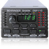
SHARK® DSP110 ENGLISH Users’s Manual Version 1.2 April 2001 www.behringer.com - Behringer SHARK DSP110 | Manual - Page 2
SHARK DSP110 SAFETY INSTRUCTIONS CAUTION: To reduce the risk of electrical shock, do not remove the cover (or back). No user serviceable parts inside; refer servicing . Damage Requiring Service: The appliance should be serviced by qualified service personnel when: - The power supply cord or the - Behringer SHARK DSP110 | Manual - Page 3
Thank you very much for expressing your confidence in BEHRINGER products by purchasing the SHARK DSP110. + This manual first describes the terminology used, so that you can fully understand the DSP110 and its functions. Please read the manual carefully and keep it for future reference. 1.1 The - Behringer SHARK DSP110 | Manual - Page 4
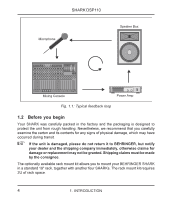
SHARK DSP110 Fig. 1.1: Typical feedback loop 1.2 Before you begin Your SHARK was carefully packed in the factory and available rack mount kit allows you to mount your BEHRINGER SHARK in a standard 19" rack, together with another four SHARKs. The rack mount kit requires 2U of rack space. 4 - Behringer SHARK DSP110 | Manual - Page 5
SHARK DSP110 Be sure that there is enough air space around the unit for cooling and please do not place the SHARK on high-temperature devices such as power amps, etc. to avoid overheating. Please use the enclosed power supply to connect the unit to the mains. The supply complies with all applicable - Behringer SHARK DSP110 | Manual - Page 6
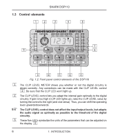
SHARK DSP110 1.3 Control elements Fig. 1.2: Front panel control elements of the DSP110 1 2 + 3 The CLIP LEVEL METER shows you whether or not the digital circuitry is driven correctly. Any corrections can be made with the CLIP LEVEL control . - Behringer SHARK DSP110 | Manual - Page 7
SHARK DSP110 4 The 4-digit DISPLAY reads the absolute values of the adjusted parameters. 5 The FB-D FILTER STATUS LEDs display the status of each of the 12 individual filters. The SHARK uses four different filter modes: s Disabled filters (which can be re-enabled with the ACTIVE button). When a - Behringer SHARK DSP110 | Manual - Page 8
SHARK DSP110 9 The LOW CUT button lets you enter the high pass filter’s cut-off by +2 dB. 11 The COMPRESSOR button gives you access to two parameters that let you adapt the DSP110’s Compressor function to the program material. Press the button once to adjust the DENSITY parameter, which controls - Behringer SHARK DSP110 | Manual - Page 9
SHARK DSP110 + When both FILTER LED and display stop flashing, the FILTER LEARN function has as free, searching filters by means of a RESET. In normal mode, which is activated after power-up, set filters are automatically released one after the other, when free filters are needed to search - Behringer SHARK DSP110 | Manual - Page 10
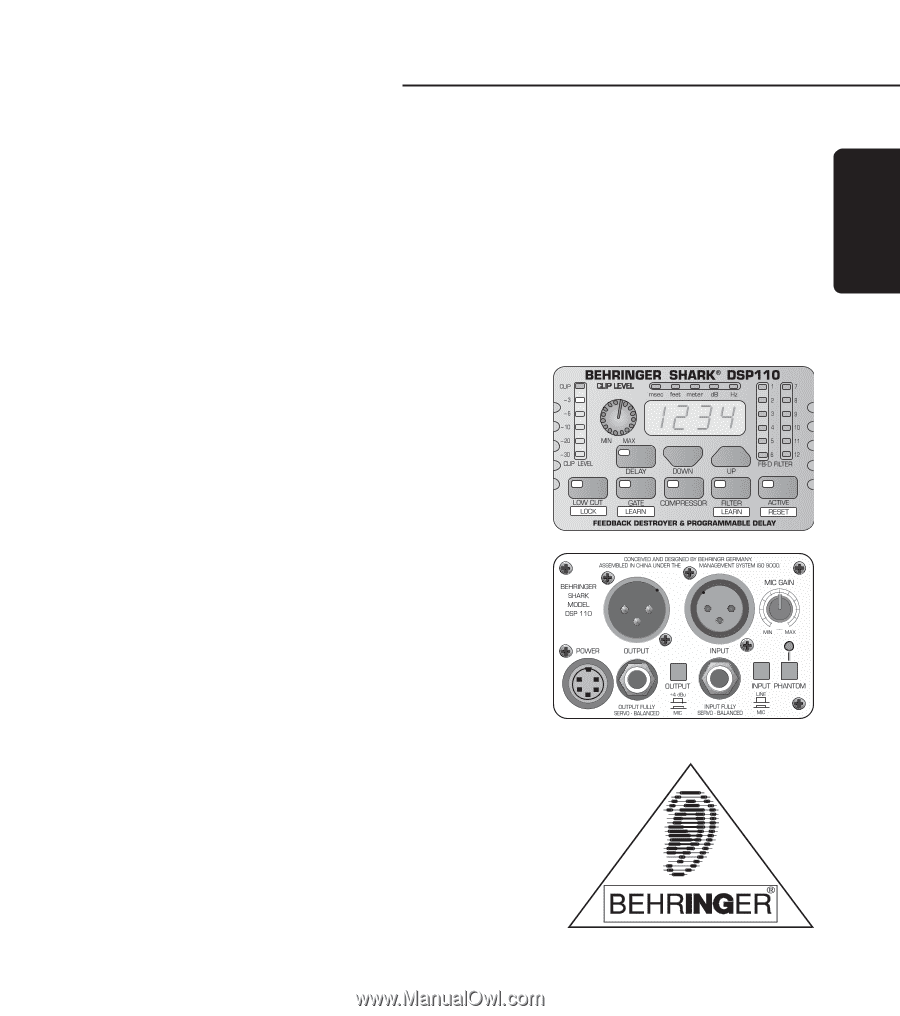
CONNECTOR to hook up the SHARK’s external power supply. 18 This is the SHARK’s balanced JACK output, which carries the same signal as the XLR output. 19 The OUTPUT LEVEL switch controls the reference level provided by the outputs of the DSP110. Possible values are: +4 dBu or microphone level. 10 - Behringer SHARK DSP110 | Manual - Page 11
up. 22 The PHANTOM switch enables the Phantom Power supply required for condenser microphones. 23 The PHANTOM CONTROL LED lights up when Phantom Power is on. 2. APPLICATIONS 2.1 Wiring the DSP110: general remarks With its great versatility the SHARK can be used for a variety of applications. This - Behringer SHARK DSP110 | Manual - Page 12
SHARK DSP110 Fig. 2.1: The SHARK connected between microphone and microphone input on console 2.1.2 Connection between line-level source and mixing console At first sight, this configuration may seem to make no sense, because line-level sources usually have no problems with feedback frequencies. - Behringer SHARK DSP110 | Manual - Page 13
SHARK DSP110 2.1.3 Connection between mixing console and power amplifier When you use the SHARK as a Delay Line unit for speaker systems placed at various positions (see chapter 2.3), you should connect the SHARK between the console’s output and the input of the power amp driving the “delayed” - Behringer SHARK DSP110 | Manual - Page 14
SHARK DSP110 2.1.4 The SHARK used in the monitor path Inserting the DSP110 in the monitor path of your mixing console several microphones and speakers placed close to each other. Especially vocal microphones pose some problems, because their volume levels must be fairly high to be able to “compete” - Behringer SHARK DSP110 | Manual - Page 15
SHARK DSP110 Fig. 2.4: Two SHARKs in the monitor path 2.1.5 The SHARK used in single channels and subgroups Whenever you want to make sure that wanted feedback such as the feedback sounds produced by a guitar won’t be removed, you should insert one or several DSP110 into “feedback-prone” single - Behringer SHARK DSP110 | Manual - Page 16
once the system has been installed and set up, open all microphone channels and monitor paths, then enable FILTER LEARN mode on your DSP110. The SHARK generates short feedbackcausing signals, which are then sent back to its input and suppressed by the filters. These filters are permanently assigned - Behringer SHARK DSP110 | Manual - Page 17
SHARK DSP110 2.2 The Feedback Destroyer in the SHARK The SHARK a filter is set. The SHARK allows you to adapt these detects feedback, the DSP110 selects the filter when you power up the SHARK). Much like search mode. Thus, the SHARK makes sure that there is feedback), the SHARK will suppress these - Behringer SHARK DSP110 | Manual - Page 18
signal, which is usually done by means of special-purpose Delay devices. You won’t need them, however, when you’ve got a SHARK, as the DSP110 integrates a Delay Line circuit giving you the same convenience of operation as dedicated devices. Simply measure the distance between the various speaker - Behringer SHARK DSP110 | Manual - Page 19
SHARK DSP110 between microphones, without producing any unpleasant side effects. A typical Gate often have high amplitudes and not only affect the sound image but can also damage power amps and/or loudspeakers. The SHARK is equipped with a tunable high pass filter that features a very high slope. - Behringer SHARK DSP110 | Manual - Page 20
SHARK DSP110 from 90 dB to 50 dB or less, which ensures the troublefree further processing the BEHRINGER DSP110 is installed with electronically servo-balanced inputs and outputs. The new circuit design features automatic hum and noise reduction for balanced signals and thus allows for trouble-free - Behringer SHARK DSP110 | Manual - Page 21
SHARK DSP110 Unbalanced use of mono 1/4" jack plugs Tip = Signal Sleeve = Ground / Shield Balanced 3.2: Different plug types Please ensure that only qualified persons install and operate the SHARK. During installation and operation the user must have sufficient electrical contact to earth. - Behringer SHARK DSP110 | Manual - Page 22
SHARK DSP110 PROCESSING Converters Sampling Rate DISPLAY Type POWER SUPPLY Mains Voltages PHYSICAL Dimensions (H * mm) x 3 1/2" (88 mm) x 5 1/8" (130 mm) approx. 0.5 kg BEHRINGER is constantly striving to maintain the highest professional standards. As a result of these efforts, modifications - Behringer SHARK DSP110 | Manual - Page 23
you begin with the work, please disconnect the Power Supply Units from the SHARKs! To mount the SHARKs on the rackmount you should use the supplied screws (type M3). You need two screws to fix one DSP110 onto the rackmount. In the bottom of your SHARK you will find two little threads. You have - Behringer SHARK DSP110 | Manual - Page 24
(optional) + Please, only use the supplied screws to install the SHARKs on the rackmount. Longer or thicker screws can damage the electronics inside of the device and doing so will void your warranty rights. You will need 2 units of space for the DSP110 rackmount. For technical reasons a little - Behringer SHARK DSP110 | Manual - Page 25
to operate the unit in compliance with the instructions given in BEHRINGER user or service manuals. 1. BEHRINGER (BEHRINGER Spezielle Studiotechnik GmbH including all BEHRINGER subsidiaries listed on the enclosed page, except BEHRINGER Japan) warrants the mechanical and electronic components of - Behringer SHARK DSP110 | Manual - Page 26
SHARK DSP110 Responsible party name: Address: Phone/Fax No.: MUSIC Group Services USA, Inc. 18912 North Creek Parkway, Suite 200 Bothell, WA 98011, USA Phone: +1 425 672 0816 Fax: +1 425 673 7647 SHARK DSP110 used in accordance with the instructions, may cause harmful interference to behringer.com
-
 1
1 -
 2
2 -
 3
3 -
 4
4 -
 5
5 -
 6
6 -
 7
7 -
8
-
9
-
10
-
11
-
12
-
13
-
14
-
15
-
16
-
17
-
18
-
19
-
20
-
21
-
22
-
23
-
24
-
25
-
26
 |
 |
SHARK
®
DSP110
Users±s Manual
Version 1.2
April 2001
www.behringer.com
ENGLISH