Biostar G31-M7G DVI Setup Manual
Biostar G31-M7G DVI Manual
 |
View all Biostar G31-M7G DVI manuals
Add to My Manuals
Save this manual to your list of manuals |
Biostar G31-M7G DVI manual content summary:
- Biostar G31-M7G DVI | Setup Manual - Page 1
G31-M7G DVI Setup Manual FCC Information and Copyright This equipment has been tested and found to comply with the limits of a Class B digital device, energy and, if not installed and used in accordance with the instructions, may cause harmful interference to radio communications. There is no - Biostar G31-M7G DVI | Setup Manual - Page 2
Memory 8 2.4 Connectors and Slots 10 Chapter 3: Headers & Jumpers Setup 12 3.1 How to Setup Jumpers 12 3.2 Detail Settings 12 Chapter 4: Useful Help 18 4.1 Driver Installation Note 18 4.2 Software 19 4.3 Extra Information 23 4.4 AMI BIOS Beep Code 25 4.5 Troubleshooting - Biostar G31-M7G DVI | Setup Manual - Page 3
Installation Guide X 1 Fully Setup Driver CD X 1 (full version manual files inside) Rear I/O Panel for ATX Case X 1 FDD Cable X 1 (optional) USB 2.0 Cable X1 (optional) S/PDIF Cable X 1 (optional) Serial ATA Power Cable X 1 (optional) Note: The package contents may differ by area or your motherboard - Biostar G31-M7G DVI | Setup Manual - Page 4
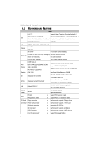
Motherboard Manual 1.3 MOTHERBOARD FEATURES SPEC LGA 775 Supports Hyper-Threading / Execute Disable Bit / Intel Core2Duo / Core2Quad / Enhanced Intel SpeedStep® / Intel Architecture-64 / CPU Pentium Dual-Core / Celeron Dual-Core / Extended Memory 64 Technology / Virtualization Celeron 4xx - Biostar G31-M7G DVI | Setup Manual - Page 5
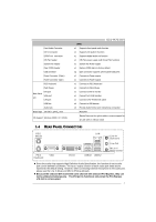
Clear CMOS header USB connector Power Connector (24pin) Power Connector (4pin) PS/2 Keyboard PS/2 Mouse Back Panel I/O DVI port VGA port LAN port USB Port Audio Jack Board Size 190 (W) x 244 (L) mm OS Support Windows 2000 / XP / VISTA G31-M7G DVI SPEC x1 Supports front panel audio - Biostar G31-M7G DVI | Setup Manual - Page 6
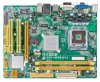
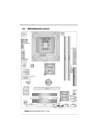
Manual 1.5 MOTHERBOARD LAYOUT JKBMS1 JATXPWR2 LGA775 CPU1 JVGA1 JCFAN1 JATXPWR1 DDR2_A1 DDR2_B1 JDVI1 JUSBV1 JSFAN1 JUSB2 LAN JRJ45USB1 JAUDIO1 JAUDIOF1 Intel G31 IDE1 JCDIN1 BAT1 Super I/O JCOM1 Codec JPRNT1 PEX16_1 JCMOS1 PCI1 JSPDIF_OUT1 PCI2 FDD1 JUSBV2 Intel BIOS - Biostar G31-M7G DVI | Setup Manual - Page 7
G31-M7G DVI CHAPTER 2: HARDWARE INSTALLATION 2.1 INSTALLING CENTRAL PROCESSING UNIT (CPU) Special Notice: Remove Pin Cap before installation, and make good preservation for future use. When the CPU - Biostar G31-M7G DVI | Setup Manual - Page 8
Motherboard Manual Step 2: Look for the triangular cut edge on socket, and the golden dot on CPU should point forwards this triangular the CPU Fan and heatsink assembly on the CPU and buckle it on the retention frame. Connect the CPU FAN power cable into the JCFAN1. This completes the installation. 6 - Biostar G31-M7G DVI | Setup Manual - Page 9
G31-M7G DVI 2.2 FAN HEADERS These fan headers support cooling-fans built in the computer. The fan cable and connector may be different according to the fan manufacturer. Connect the fan cable to the connector while matching the black wire to pin#1. JCFAN1: CPU Fan Header 4 1 Pin Assignment 1 - Biostar G31-M7G DVI | Setup Manual - Page 10
DDR2_A 1 DDR2_B1 Motherboard Manual 2.3 INSTALLING SYSTEM MEMORY A. DDR2 module 1. Unlock a DIMM slot by pressing the retaining clips outward. Align a DIMM on the slot such that the notch on the DIMM matches the - Biostar G31-M7G DVI | Setup Manual - Page 11
Module 256MB/512MB/1GB/2GB 256MB/512MB/1GB/2GB G31-M7G DVI Total Memory Size Max is 4GB. C. Dual Channel Memory Installation To trigger the Dual Channel function of the motherboard, the memory module must meet the following requirements: Install memory module of the same density in pairs, shown - Biostar G31-M7G DVI | Setup Manual - Page 12
Motherboard Manual 2.4 CONNECTORS AND SLOTS FDD1: Floppy Disk Connector The motherboard provides a standard floppy disk connector that supports 360K, 720K, 1.2M, 1.44M and 2.88M floppy disk types. This connector supports the provided floppy drive ribbon cables. 2 34 1 33 IDE1: IDE/ATAPI - Biostar G31-M7G DVI | Setup Manual - Page 13
G31-M7G DVI PEX16_1: PCI-Express x16 Slot - PCI-Express 1.0a compliant. - Maximum theoretical realized bandwidth of 4GB/s simultaneously per direction, for an aggregate of 8GB/s totally. - PCI-Express supports a raw bit-rate of 2.5Gb/s on the data pins. - 2X bandwidth over the traditional PCI - Biostar G31-M7G DVI | Setup Manual - Page 14
Motherboard Manual CHAPTER 3: HEADERS & JUMPERS SETUP 3.1 HOW TO SETUP JUMPERS The "open". Pin opened Pin closed Pin1-2 closed 3.2 DETAIL SETTINGS JPANEL1: Front Panel Header This 16-pin connector includes Power-on, Reset, HDD LED, Power LED, and speaker connection. It allows user to connect - Biostar G31-M7G DVI | Setup Manual - Page 15
G31-M7G DVI JATXPWR1: ATX Power Source Connector This connector allows user to connect 24-pin power connector on the ATX Standby Voltage+5V 10 +12V 11 +12V 12 +3.3V JATXPWR2: ATX Power Source Connector By connecting this connector, it will provide +12V to CPU power circuit. 2 1 3 4 Pin - Biostar G31-M7G DVI | Setup Manual - Page 16
Motherboard Manual JUSB3/JUSB4: Headers for USB 2.0 Ports at Front Panel This motherboard provides 2 USB 2.0 headers, which allows user to connect additional USB cable on the PC front panel, and also can be connected with internal USB devices, like USB card reader. JUSB3 JUSB4 2 10 Pin - Biostar G31-M7G DVI | Setup Manual - Page 17
G31-M7G DVI SATA1~SATA4: Serial ATA Connectors The motherboard has a PCI to SATA Controller with 4channels SATA interface, it satisfies the SATA 2.0 spec and with to restore the BIOS safe setting and the CMOS data, please carefully follow the procedures to avoid damaging the motherboard. 13 Pin 1-2 - Biostar G31-M7G DVI | Setup Manual - Page 18
Motherboard Manual JAUDIOF1: Front Panel Audio Header This header allows user to connect the front audio output cable with the PC front panel. This header allows only HD audio front panel connector; AC'97 connector is not acceptable. 10 9 21 Pin Assignment 1 Mic Left in 2 Ground 3 Mic Right in 4 - Biostar G31-M7G DVI | Setup Manual - Page 19
JPRNT1: Printer Port Connector This header allows you to connector printer on the PC. G31-M7G DVI 2 1 25 Pin Assignment 1 -Strobe 2 -ALF 3 Data 0 4 - SCLT 26 Key JCOM1: Serial port Connector The motherboard has a Serial Port Connector for connecting RS-232 Port. 2 10 1 9 Pin - Biostar G31-M7G DVI | Setup Manual - Page 20
file SETUP.EXE under your optical drive. A. Driver Installation To install the driver, please click on the Driver icon. The setup guide will list the compatible driver for your motherboard and operating system. Click on each device driver to launch the installation program. B. Software Installation - Biostar G31-M7G DVI | Setup Manual - Page 21
G31-M7G DVI 4.2 SOFTWARE Installing Software 1. Insert the Setup CD to the optical drive. The drivers installation program would appear if the Autorun function has been enabled. 2. Select Software Installation, and then click on the respective software title. 3. Follow the on-screen instructions to - Biostar G31-M7G DVI | Setup Manual - Page 22
motherboard/BIOS/CPU/video/ device/OS service. If you are not using Outlook Express as your default e-mail client application, you may need to save the system information to a .txt file and send the file to our tech support with other e-mail application. Go to the following web http://www.biostar - Biostar G31-M7G DVI | Setup Manual - Page 23
G31-M7G DVI BIOS Update BIOS Update is a convenient utility which allows you to update your motherboard BIOS under Windows system. AWARD BIOS Show current BIOS information AMI BIOS Clear CMOS function (Only for AWARD BIOS) Save current BIOS to a .bin file Update BIOS with a BIOS file - Biostar G31-M7G DVI | Setup Manual - Page 24
Motherboard Manual Before doing this, please download the proper BIOS file from the website. For AWARD BIOS, update BIOS procedure should be run with Clear CMOS function, so please check on Clear CMOS first. Then click Update BIOS button, a dialog will show for asking you backup - Biostar G31-M7G DVI | Setup Manual - Page 25
G31-M7G DVI 4.3 EXTRA INFORMATION CPU Overheated If the system shutdown automatically after power on system for seconds, that means the CPU protection function has been activated. When the CPU is over heated, the motherboard will shutdown automatically to avoid a damage of the CPU, and the system - Biostar G31-M7G DVI | Setup Manual - Page 26
Flasher 1. Go to the website to download the latest BIOS file for the motherboard. 2. Then, save the BIOS file into a USB pen drive or a floppy disk. 3. Insert the USB pen drive or the floppy disk that contains the BIOS file to the USB port or the floppy disk drive. 4. Power on or reset the computer - Biostar G31-M7G DVI | Setup Manual - Page 27
(system video adapter) Troubleshooting POST BIOS Beep Codes Number of Beeps Troubleshooting Action 1, 3 Reseat the memory, or replace with known good modules. Fatal error indicating a serious problem with the system. Consult your system manufacturer. Before declaring the motherboard beyond - Biostar G31-M7G DVI | Setup Manual - Page 28
Motherboard Manual 4.5 TROUBLESHOOTING Probable Solution 1. No power to the system at all 1. Make sure power cable is Power light don't illuminate, fan securely plugged in. inside power supply does not turn 2. Replace cable. on. 3. Contact technical support says "Invalid Review system's - Biostar G31-M7G DVI | Setup Manual - Page 29
G31-M7G DVI This page is intentionally left blank. 27 - Biostar G31-M7G DVI | Setup Manual - Page 30
Motherboard Manual APPENDIX: SPEC IN OTHER LANGUAGES GERMAN Spezifikationen LGA 775 Unterstützt Hyper-Threading / Execute Disable Bit / Intel Core2Duo / Core2Quad / Enhanced Intel SpeedStep® / IntelArchitecture-64 / CPU Pentium Dual-Core / Celeron Dual-Core / Extended Memory 64 Technology / - Biostar G31-M7G DVI | Setup Manual - Page 31
DVI-Anschluss Rückseiten-E VGA-Anschluss /A LAN-Anschluss USB-Anschluss Audioanschluss Platinengröße 190 mm (B) X 244 mm (L) OS-Unterstüt Windows 2000 / XP / VISTA zung G31-M7G DVI unterstützt 2 x2 Fronttafel-USB-Anschlüsse x1 x1 x1 x1 x1 x1 x1 x4 x3 MicroATX Biostar behält sich das Recht vor - Biostar G31-M7G DVI | Setup Manual - Page 32
Motherboard Manual FRANCE SPEC LGA 775 Prend en charge les technologies Hyper-Threading / Processeurs Intel Core2Duo / Core2Quad d'exécution de bit de désactivation / Intel SpeedStep® UC / PentiumDual-Core / Celeron Dual-Core / optimisée/ d'architecture Intel 64 / de mémoire Celeron 4xx é - Biostar G31-M7G DVI | Setup Manual - Page 33
G31-M7G DVI SPEC Connecteur IDE Chaque connecteur prend en charge 2 périphériques E/S du Port DVI x1 panneau Port VGA x1 arrière Port LAN x1 Port USB x4 Fiche audio x3 Dimensions 190 mm (l) X 244 mm (H) de la carte MicroATX Support SE Windows 2000 / XP / VISTA Biostar se réserve - Biostar G31-M7G DVI | Setup Manual - Page 34
Motherboard Manual ITALIAN SPECIFICA LGA 775 Supporto di Hyper-Threading / Execute Disable CPU Processore Intel Core2Duo / Core2Quad / Pentium Dual-Core / Bit / Enhanced Intel SpeedStep® / Architettura Intel 64 / Tecnologia Extended Memory GMA 3100 La memoria video condivisa massima è di - Biostar G31-M7G DVI | Setup Manual - Page 35
G31-M7G DVI SPECIFICA Connettore IDE x1 Ciascun DVI x1 pannello Porta VGA x1 posteriore Porta LAN x1 Porta USB x4 Connettore audio x3 Dimension 190 mm (larghezza) x 244 mm i scheda (altezza) MicroATX Sistemi Biostar si riserva il diritto di aggiungere o operativi Windows 2000 / XP - Biostar G31-M7G DVI | Setup Manual - Page 36
Motherboard Manual SPANISH Especificación LGA 775 Admite Hyper-Threading / Bit de deshabilitación de Procesador Intel Core2Duo / Core2Quad / ejecución / Intel SpeedStep® Mejorado / Intel CPU Pentium Dual-Core / Celeron Dual-Core / Architecture-64 / Tecnología Extended Memory 64 / Celeron 4xx - Biostar G31-M7G DVI | Setup Manual - Page 37
G31-M7G DVI Especificación Conector IDE X1 Cada conector soporta 2 DVI X1 trasero de Puerto VGA X1 E/S Puerto de red local X1 Puerto USB X4 Conector de sonido X3 Tamaño de 190 mm. (A) X 244 Mm. (H) la placa MicroATX Soporte de sistema Windows 2000 / XP / VISTA operativo Biostar - Biostar G31-M7G DVI | Setup Manual - Page 38
Motherboard Manual PORTUGUESE ESPECIFICAÇÕES LGA 775 Suporta as tecnologias Hyper-Threading / Execute Processador Intel Core2Duo / Core2Quad CPU Disable Bit / Enhanced Intel SpeedStep® / Intel / PentiumDual-Core / Celeron Dual-Core / Arquitecture -64 / Extended Memory ção SATA versão 2.0. - Biostar G31-M7G DVI | Setup Manual - Page 39
G31-M7G DVI ESPECIFICAÇÕES Conector da unidade DVI x1 aídas no Porta VGA x1 painel Porta LAN x1 traseiro Porta USB x4 Tomada de áudio x3 Tamanho da placa 190 mm (L) X 244 mm (A) MicroATX Sistemas A Biostar reserva-se o direito de adicionar ou remover operativos Windows 2000 / XP - Biostar G31-M7G DVI | Setup Manual - Page 40
Motherboard Manual POLISH SPEC LGA 775 Obsługa Hyper-Threading / Execute Disable Bit / Procesor Procesor Intel Core2Duo / Core2Quad / Enhanced Intel SpeedStep® / Intel Architecture-64 / Pentium Dual-Core / Celeron Dual-Core / Extended Memory współdzielonej pamięci video wynosi 256MB ITE 8712F - Biostar G31-M7G DVI | Setup Manual - Page 41
G31-M7G DVI SPEC Złącze IDE x1 Każde złącze obsługuje 2 urządzenia IDE Złącze x1 Port DVI x1 Back Panel Port VGA x1 I/O Port LAN x1 Port USB x4 Gniazdo audio x3 Wymiary płyty 190 mm (S) X 244 mm (W) MicroATX Obsluga systemu Windows 2000 / XP / VISTA operacyjne go Biostar - Biostar G31-M7G DVI | Setup Manual - Page 42
Motherboard Manual RUSSIAN СПЕЦ CPU LGA 775 Hyper-Threading / Execute Intel Core2Duo / Core2Quad / Disable Bit / Enhanced Intel SpeedStep® / Intel ый Pentium Dual-Core / Celeron Dual-Core / Architecture-64 / Extended Memory 64 Technology / Celeron 4xx FSB 800 / 1066 / 1333 / - Biostar G31-M7G DVI | Setup Manual - Page 43
G31-M7G DVI СПЕЦ IDE 2 x1 SATA x4 1 SATA x1 x1 CD x1 CD S/PDIF x1 x1 x1 CMOS x1 USB 2 USB x2 24 вывод) x1 4 вывод) x1 PS/2 x1 Мышь PS/2 x1 Задняя Порт DVI x1 панель Порт VGA x1 Порт LAN - Biostar G31-M7G DVI | Setup Manual - Page 44
Motherboard Manual ARABIC Hyper-Threading / Execute Disable Bit LGA 775 Enhanced Intel SpeedStep® / Intel Architecture-64 / Intel Core2Duo / Core2Quad Extended Memory 64 Technology / Virtualization Pentium Dual-Core / Celeron Dual-Core / Technology - Biostar G31-M7G DVI | Setup Manual - Page 45
Smart Fan 1 1 1 CMOS USB 2 USB 24 1 4 1 1 PS/2 1 PS/2 1 DVI 1 VGA 1 4 USB 3 MicroATX 190 244 X Biostar Windows 2000 / XP / VISTA 43 - Biostar G31-M7G DVI | Setup Manual - Page 46
Motherboard Manual JAPANESE 仕様 LGA 775 Hyper-Threading / Execute Disable Bit / Enhanced Intel Intel Core2Duo / Core2Quad / SpeedStep® / Intel Architecture-64 / Extended CPU Pentium Dual-Core / Celeron Dual-Core / Memory 64 Technology / Virtualization Technologyをサ Celeron 4xx processor - Biostar G31-M7G DVI | Setup Manual - Page 47
PS/2マウス I/O DVIポート VGAポート LANポート USB 190 mm (幅) X 244 mm (高さ) OS Windows 2000 / XP / VISTA G31-M7G DVI 仕様 x1 2 x1 1 x1 x1 2つのIDE x4 1つのSATA x1 x1 x1 CD x1 x1 CPU x1 x1 2 USB x2 ます x1 x1 x1 x1 x1 x1 x1 x4 x3 MicroATX Biostar OS 2008
-
 1
1 -
 2
2 -
 3
3 -
 4
4 -
 5
5 -
 6
6 -
 7
7 -
8
-
9
-
10
-
11
-
12
-
13
-
14
-
15
-
16
-
17
-
18
-
19
-
20
-
21
-
22
-
23
-
24
-
25
-
26
-
27
-
28
-
29
-
30
-
31
-
32
-
33
-
34
-
35
-
36
-
37
-
38
-
39
-
40
-
41
-
42
-
43
-
44
-
45
-
46
-
47
 |
 |

G31-M7G DVI Setup Manual
FCC Information and Copyright
This equipment has been tested and found to comply with the limits of a Class
B digital device, pursuant to Part 15 of the FCC Rules. These limits are designed
to provide reasonable protection against harmful interference in a residential
installation. This equipment generates, uses, and can radiate radio frequency
energy and, if not installed and used in accordance with the instructions, may
cause harmful interference to radio communications. There is no guarantee
that interference will not occur in a particular installation.
The vendor makes no representations or warranties with respect to the
contents here and specially disclaims any implied warranties of merchantability
or fitness for any purpose. Further the vendor reserves the right to revise this
publication and to make changes to the contents here without obligation to
notify any party beforehand.
Duplication of this publication, in part or in whole, is not allowed without first
obtaining the vendor’s approval in writing.
The content of this user’s manual is subject to be changed without notice and
we will not be responsible for any mistakes found in this user’s manual. All the
brand and product names are trademarks of their respective companies.