Biostar G31-M7G DVI Bios Setup
Biostar G31-M7G DVI Manual
 |
View all Biostar G31-M7G DVI manuals
Add to My Manuals
Save this manual to your list of manuals |
Biostar G31-M7G DVI manual content summary:
- Biostar G31-M7G DVI | Bios Setup - Page 1
G31-M7G DVI BIOS Manual BIOS Setup 1 1 Main Menu 3 2 Advanced Menu 7 3 PCIPnP Menu 18 4 Boot Menu 22 5 Chipset Menu 25 6 Performance Menu 30 7 Exit Menu 32 i - Biostar G31-M7G DVI | Bios Setup - Page 2
G31-M7G DVI BIOS Manual BIOS Setup Introduction T he purpose of this manual is to describe the settings in the AMI BIOS Setup program on this motherboard. The Setup program allows users to modify the basic system configuration and save these settings to CMOS RAM. T he power of CMOS RAM is supplied - Biostar G31-M7G DVI | Bios Setup - Page 3
G31-M7G DVI BIOS Manual PCI Bus Support T his AMI BIOS also supports Version 2.3 of the Intel PCI (Peripheral Component Interconn ect) local bus speci fication. DRAM S upport DDR2 SDRAM (Double Data Rate II Synchronous DRAM) is supported. Supported CP Us T his AMI BIOS supports the Intel CPU. - Biostar G31-M7G DVI | Bios Setup - Page 4
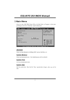
G31-M7G DVI BIOS Manual 1 Main Menu Once you enter AMI BIOS Setup Utility, the Main Menu will appear on the screen providing an overview of the basic system inform ation. Main Advan ced BIOS SETU P U TILITY PCIPnP Boot Chipset Performance Exit System Overvie w AMI BIOS Version :01. 01.01 - Biostar G31-M7G DVI | Bios Setup - Page 5
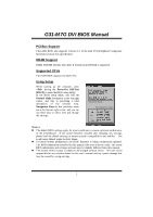
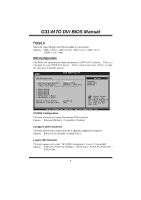
G31-M7G DVI BIOS Manual Floppy A Select the type of floppy disk drive installed in your system. Options: 360K, 5.25 in / 1.2M, 5.25 in / 720K, 3.5 in / 1.44M, 3.5 in / 2.88M, 3.5 in / None IDE Configuration T he BIOS will automatically detect the presence of ID E/SAT A devices. There is a sub-menu - Biostar G31-M7G DVI | Bios Setup - Page 6
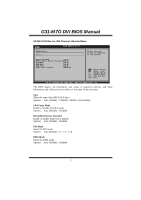
G31-M7G DVI BIOS Manual SATA1/2/3/4 Dev ice; IDE Channel 1 Master/Slave Main BIOS SETU P U TILITY SATA1 Device Device : Type [Aut o] LBA/Large Mode [Aut o] Block (Multi-S ector Transfer)[Aut o] PIO Mode [Aut o] DMA Mode [Aut o] S.M.A.R.T [Aut o] 32Bit Data Tra nsfer [Ena bled] - Biostar G31-M7G DVI | Bios Setup - Page 7
G31-M7G DVI BIOS Manual S.M.A.R.T Set the Smart Monitoring, Analysis, and Reporting T echnology. Options: Auto (Default) / Disabled / Enabled 32Bit Data Transfer Enable or disable 32-bit data transfer. Options: Enabled (Default) / Disabled Hard Disk Write Protect Disable or enable device write - Biostar G31-M7G DVI | Bios Setup - Page 8
G31-M7G DVI BIOS Manual 2 Advanced Menu T he Advanced Menu allows you to configu re the settings of CPU, Super I/O, Power Management, and other system devices. Notice z Beware of that setting inappropriate values in items of this menu may cause system to malfunction. Main Advan ced BIOS SETU P - Biostar G31-M7G DVI | Bios Setup - Page 9
G31-M7G DVI BIOS Manual C1E Support and prefetches dat a and instructions from the memory into the Level 2 cache that find out the highest input value CPUID recognizes. T his determines the kind ofbasic information CPUID can provide the operating system. Options: Disabled (Default) / Enabled Intel - Biostar G31-M7G DVI | Bios Setup - Page 10
G31-M7G DVI BIOS Manual PECI T his item allows you to control the PECI function for the processor which supports technology built into some Intel processors that allows the clock BIOS SETU P U TILITY Configure ITE8 712 Super IO Chipse t Onboard Floppy Controller Serial Port1 A ddress Parallel Port - Biostar G31-M7G DVI | Bios Setup - Page 11
G31-M7G DVI BIOS Manual Onboard Floppy Controller Select enabled if your system has a floppy port as Standard Printer Port. EPP Using Parallel Port as Enhanced Parallel Port. ECP Using Parallel port as Extended Capabilities Port. ECP+EPP Using Parallel port as ECP & EPP mode. Parallel Port - Biostar G31-M7G DVI | Bios Setup - Page 12
G31-M7G DVI BIOS Manual Restore on AC Power Loss T his setting specifies how your Function[Dis abled] Enables Hardware Health Monitoring Device. CPU Temperatur e CPU FAN Speed SYS FAN Speed CPU Vcore Chipset Voltag e +3.30V +5.00V +12.0V FSB Voltage Memory Voltage 5V(SB) S elect Screen S - Biostar G31-M7G DVI | Bios Setup - Page 13
G31-M7G DVI BIOS Manual Smart Fan Configuration Advan ced BIOS SETU P U TILITY Smart Fan Conf Control Mode T his item provides several operation modes of the fan. Options: Quiet / Performan ce / Manual Fan Ctrl OFF(℃ ) If the CPU/System T emperature is lower than the set value, FAN will - Biostar G31-M7G DVI | Bios Setup - Page 14
G31-M7G DVI BIOS Manual Fan Ctrl BIOS SETU P U TILITY ACPI Settings Suspend mode [S1( POS)] ACPI Version F eatures [ACP I v1.0] ACPI APIC supp ort [Ena bled] AMI OEMB table [Ena bled] Headless mode [Dis abled] Energy Lake Fe ature [Dis abled] APIC ACPI SCI IRQ [Dis abled] USB Device - Biostar G31-M7G DVI | Bios Setup - Page 15
G31-M7G DVI BIOS Manual ACPI APIC support T his item is used to enable or disable the motherboard's APIC (Advan ced Programmable Interrupt Controller). T he APIC provides multiprocessor support / Enabled USB Dev ice Wakeup from S3/S4 T his item allows you to enable or disabled the USB resume from S3 - Biostar G31-M7G DVI | Bios Setup - Page 16
G31-M7G DVI BIOS Manual Resume On Ring T his item allows you control the wake on ring this function to work, you may need a LAN add-on card which supports the Wake on LAN function. Set the Wake on LAN (WOL) jumper on motherboard to enable i f applicable. Options: Disabled (Default) / Enabled Resume - Biostar G31-M7G DVI | Bios Setup - Page 17
G31-M7G DVI BIOS Manual USB Configuration T his item shows the USB controller and using USB device information. Advan ced BIOS SETU P U TILITY USB Configurat ion Module Version - 2.24.2-13.4 USB Devices En abled: Legacy USB Sup port USB 2.0 Contro ller Mode BIOS EHCI Hand -Off [Ena bled] [HiS - Biostar G31-M7G DVI | Bios Setup - Page 18
G31-M7G DVI BIOS Manual USB Mass Storage Dev ice Configuration Advanced BIOS SETUP UTILITY USB Mass Storage Device Configuration USB Mass Storage Reset Delay [20 Sec] Device # Emulation Type [Auto] Number of seconds POST waits for the USB mass storage device after start unit command. Select - Biostar G31-M7G DVI | Bios Setup - Page 19
G31-M7G DVI BIOS Manual 3 PCIPnP Menu T his section describes con figuring the PCI bus system. PCI, or Personal Computer Interconn ect, is a system which allows I/O devices lay OS When set to YES, BIOS will only initialize the PnP cards used for the boot sequen ce (VGA, IDE, SCSI). The rest of the - Biostar G31-M7G DVI | Bios Setup - Page 20
G31-M7G DVI BIOS Manual PCI Latency Timer T his item controls how long a PCI device can hold the PCI bus before another takes over. T he longer the latency, the longer the PCI device can retain control of the bus before handing it over to another PCI device. Options: 64 (Default) / 32 / 96 / 128 / - Biostar G31-M7G DVI | Bios Setup - Page 21
G31-M7G DVI BIOS Manual IRQ3/4/5/7/9/10/11/14/15 T hese items will allow you to assign each system interrupt a type, depending on the type of device using the interrupt. T he option "Available" means the IRQ is going to assign automatically. Options: Available (Default) / Reserved DMA Channel - Biostar G31-M7G DVI | Bios Setup - Page 22
G31-M7G DVI BIOS Manual SB PCIE Ports Configuration BIOS SETU P U TILITY PCIPnP PCIE Ports Con figuration PCIE Port 0 PCIE Port 1 PCIE Port 2 PCIE Port 3 PCIE Port 4 PCIE Port 5 PCIE High Pr iority Port [Aut o] [Aut o] [Aut o] [Aut o] [Aut o] [Aut o] [Dis abled] PCIE Port 0 IOxAPIC Enable [Dis - Biostar G31-M7G DVI | Bios Setup - Page 23
G31-M7G DVI BIOS Manual 4 Boot Menu T his menu allows you to setup the system boot options. Main Advan ced BIOS SETU P U TILITY PCIPnP Boot Chipset Performance Exit Boot Settings > Boot Device Priority > Hard Disk Dr ives > Removable Dr ives > CD/DVD Drive s > Boot Setting s Configuration - Biostar G31-M7G DVI | Bios Setup - Page 24
G31-M7G DVI BIOS Manual CD/DV D Drives T he BIOS will attempt to arrange the CD/DVD drive boot sequence automatically. You can also change the booting sequence. The number of device items that appears on the screen depends on the number of devices installed in the system. Boot Settings - Biostar G31-M7G DVI | Bios Setup - Page 25
G31-M7G DVI BIOS Manual Bootup Num-L ock Selects the NumLock State after the system switched on. Options: ON (Default) / OFF 24 - Biostar G31-M7G DVI | Bios Setup - Page 26
G31-M7G DVI BIOS Manual 5 Chipset Menu T his submenu allows you to configure the speci fic features of the chipset installed on your system. T his chipset manage bus speeds and access to system memory resources, such as DRAM. It also coordinates communications with the PCI bus. Notice z Beware of - Biostar G31-M7G DVI | Bios Setup - Page 27
G31-M7G DVI BIOS Manual North Bridge Configuration BIOS SETU P U TILITY Chipset North Bridge C hipset Configuratio n Memory Remap F eature PCI MMIO All ocation: Memory Hole [E nabled] [D isabled] Initiate Graph ic Adapter [P EG/PCI] Internal Graph ics Mode Select [E nabled,8MB] PEG Port - Biostar G31-M7G DVI | Bios Setup - Page 28
G31-M7G DVI BIOS Manual PEG Port T his BIOS feature is a toggle that enables or disables the PCI Express port. Options: Auto (Default) / Disabled Video Function Configuration BIOS SETU P U TILITY Chipset Video amount of display, texturing and buffer memory after the operating system has booted. - Biostar G31-M7G DVI | Bios Setup - Page 29
G31-M7G DVI BIOS Manual South Bridge Configuration BIOS SETU P U TILITY Chipset South Bridge C hipset Configuratio n USB Functions USB 2.0 Contro ller Audio Controll er [8 USB Ports] [E nabled] [A zalia] Onboard Lan Co ntrol Onboard Lan Bo ot ROM MAC ID Informa tion [E nabled] [D isabled] - Biostar G31-M7G DVI | Bios Setup - Page 30
G31-M7G DVI BIOS Manual Onboard Lan Control T his item allows you to enable or disable the (Default) / Enabled MAC ID Information T his item shows the LAN MAC ID. SMBUS Controller T his BIOS feature controls the I/O buffers fo r the SMBus. Options: Enabled (Default) / Disabled SLP_S4# Min. Assertion - Biostar G31-M7G DVI | Bios Setup - Page 31
G31-M7G DVI BIOS Manual 6 Performance Menu T his submenu allows you to change voltage and clock of various devices. (Howev er, we suggest you to use the default setting. Changing the voltage and clock improperly may damage the device.) Notice z Beware of that setting inappropriate values in items - Biostar G31-M7G DVI | Bios Setup - Page 32
G31-M7G DVI BIOS Manual CPU Voltage T his item allows you to select CPU Voltage Control. Options: Default (Default) / +5% / +10% / +15% DRAM Frequency T his item allows you to control the Memory Clock. Options: Auto (Default) / DDR2 533Mhz / DDR2 667Mhz / DDR2 800Mhz Configure DRAM Timing by SP D - Biostar G31-M7G DVI | Bios Setup - Page 33
G31-M7G DVI BIOS Manual 7 Exit Menu T his menu allows you to load the optimal default settings, and save or discard the changes to the BIOS items. Main Advan ced PCIPnP Exit Options Save Changes a nd Exit Discard Change s and Exit Discard Change s Load Optimal D efaults BIOS BIOS when problem - Biostar G31-M7G DVI | Bios Setup - Page 34
G31-M7G DVI BIOS Manual Security T his sub-menu allows you to provide/revise supervisor and user password. BIOS SETU P U TILITY Exit Security Setti ngs Supervisor Pas sword :Not Installe d User Password :Not Installe d Change Supervi sor Password User Access Le vel Change User - Biostar G31-M7G DVI | Bios Setup - Page 35
G31-M7G DVI BIOS Manual Passw ord Check T his item is for setting the timing that checking password. Options: Setup ction is enabled and an attempt is made to write to the boot sector, BIOS will display a warning message on the screen and sound an alarm beep. Options: Disabled (Default) / Enabled 34
-
 1
1 -
 2
2 -
 3
3 -
 4
4 -
 5
5 -
 6
6 -
 7
7 -
8
-
9
-
10
-
11
-
12
-
13
-
14
-
15
-
16
-
17
-
18
-
19
-
20
-
21
-
22
-
23
-
24
-
25
-
26
-
27
-
28
-
29
-
30
-
31
-
32
-
33
-
34
-
35
 |
 |

G31-M7G DVI BIOS Manual
i
BIOS Setup
.................................................................................................
1
1 Main Menu
...............................................................................................
3
2 Advanced Menu
.......................................................................................
7
3 PCIPnP Menu
........................................................................................
18
4 Boot Menu
..............................................................................................
22
5 Chipset Menu
.........................................................................................
25
6 Performance Menu
...............................................................................
30
7 Exit Menu
...............................................................................................
32