Biostar M7VIG PRO M7VIG Pro user's manual
Biostar M7VIG PRO Manual
 |
View all Biostar M7VIG PRO manuals
Add to My Manuals
Save this manual to your list of manuals |
Biostar M7VIG PRO manual content summary:
- Biostar M7VIG PRO | M7VIG Pro user's manual - Page 1
radio frequency energy and, if not installed and used in accordance with the instructions, may cause harmful interference to radio communications. There is no guarantee that for any mistakes found in this user's manual. All the brand and product names are trademarks of their respective companies. i - Biostar M7VIG PRO | M7VIG Pro user's manual - Page 2
& Slots 6 ESPAÑOL 11 Características del M7VIG Pro 11 Contenido del Paquete...12 Disposición del M7VIG Pro 12 Instalación de la CPU ...13 Módulos DDR DIMM: DDR1-2 14 Módulo SDR DIMM: SDR1-2 14 Conectores, Cabezales, Puentes y Ranuras 16 TROUBLE SHOOTING 21 SOLUCIÓN DE PROBLEMAS 22 ii - Biostar M7VIG PRO | M7VIG Pro user's manual - Page 3
operating systems such as Windows NT, Windows 2000, Windows ME, Windows XP, LINUX and SCO UNIX. AC'97 2.2 compatible. High S/N ratio meets PC 99 requirements. 6CH DAC, applicable for leading motherboard chipsets. Line-in phonejack share with rear out. Supports front audio pin head functions. 1 - Biostar M7VIG PRO | M7VIG Pro user's manual - Page 4
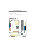
DDeessccrriippttiioonn Package contents HDD Cable X 1, FDD Cable X 1, Fully Setup Driver CD X 1 Flash Memory Writer for BIOS update X 1 USB Cable X 2 (Optional) Rear I/O Panel for ATX Case X 1 (Optional) Layout of M7VIG Pro JKBMS1 1 JKBV1 1 JUSBV1 JATXPWR1 JUSBLAN1 JCOM1 FDD1 JPRNT1 JCFAN1 - Biostar M7VIG PRO | M7VIG Pro user's manual - Page 5
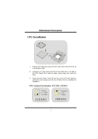
Pin A in the socket and lock for the white dot or cut edge in the CPU. Match Pin A with the white dot/cut edge then insert the CPU. 3. Press the lever down. Then Put the fan on the CPU and buckle it and put the fan's power port into the JCFAN1, then to - Biostar M7VIG PRO | M7VIG Pro user's manual - Page 6
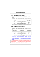
configuration is only for reference. When you use DDR SDRAM, the memory power will automatically set to 2.5V. When you use SDRAM, the memory power will automatically set to 3.3V. For the above settings, you can only use one kind of memory on this motherboard. It is forbidden to insert both kind of - Biostar M7VIG PRO | M7VIG Pro user's manual - Page 7
MMootthheerrbbooaarrdd DDeessccrriippttiioonn How to install a DIMM Module DDR SDRAM 1. The DIMM socket has a " Plastic Safety Tab", and the DIMM memory module has an "Asymmetrical notch", so the DIMM memory module can only fit into the slot in one direction. 2. Push the tabs out. Insert the DIMM - Biostar M7VIG PRO | M7VIG Pro user's manual - Page 8
Your monitor will attach directly to that video card. This motherboard supports video cards for PCI slots, but it is also equipped with an Accelerated Graphics Port (AGP). An AGP card will take advantage of AGP technology for improved video efficiency and performance, especially with 3D graphics - Biostar M7VIG PRO | M7VIG Pro user's manual - Page 9
MMootthheerrbbooaarrdd DDeessccrriippttiioonn Power Connectors: JATXPWR1 JATXPWR1 (ATX Main Power Conn.) DIMM Power Selection Connector: JDIMMVOLT 2 1 JDIMMVOLT (Default ==> 2.5V) Pin 1-2 on ==> 2.5V Pin 3-4 on ==> 2.6V Pin 5-6 on ==> 2.7V Pin 7-8 on ==> 2.8V It strongly recommended to set DDR - Biostar M7VIG PRO | M7VIG Pro user's manual - Page 10
Data(+) Pin7,8 ==> Ground Pin9 ==> KEY Pin10 ==> NA 5V/ 5VSB Selection for USB: JUSBV1 1 Pin 1-2 on ==> 5V JUSBV1 Pin 2-3 on ==> 5V_SB CPU Frequency Selection: JCLK1 1 JCLK1 On ==> 100MHz Off ==> 133MHz 5V/ 5VSB Selection for Keyboard: JKBV1 1 JKBV1 Pin 1-2 on ==> 5V Pin 2-3 on ==> 5V_SB - Biostar M7VIG PRO | M7VIG Pro user's manual - Page 11
/ Secondary Selection: JCODECSEL 1 JCODECSEL Pin 1-2 ==> On board primary Codec (Default) Pin 2-3 ==> CNR primary Codec Front Panel Connector: JPANEL1 24 IR ON/OFF (-) PWR_LED (+) (+) SLP 2 23 IR SPK ==> Speaker Conn. HLED ==> Hard Driver LED RST RST IR (-) HLED (+) SLP ==> Reset - Biostar M7VIG PRO | M7VIG Pro user's manual - Page 12
Pin3 ==> Mic Power Pin5 ==> RT Line Out Pin7 ==> Reserved Pin9 ==> LFT Line Out Pin11==> RT Line In Pin13 ==> LFT Line In Pin2 ==> Ground Pin4 ==> Audio Power Pin6 ==> RT Line Out Pin8 ==> KEY Pin10 ==> LFT Line Out Pin12 ==> RT Line In Pin14 ==> LFT Line In Back Panel Connectors JKBMS1 JUSBLAN1 - Biostar M7VIG PRO | M7VIG Pro user's manual - Page 13
Bus de 32-bit, y una ranura AGP. Conforma con las especificaciones del factor de forma de tamaño PC Micro-ATX. Soporta sistemas operativos populares tales como Windows NT, Windows 2000, Windows ME, Windows XP, LINUX y SCO UNIX. Compatible con AC'97 2.2. High S/N ratio reune los requisitos del PC 99 - Biostar M7VIG PRO | M7VIG Pro user's manual - Page 14
Paquete Cable HDD X 1, Cable FDD X 1, Configuración Completa del Driver CD X 1 Flash Memory Writer para actualización del BIOS X 1 Cable USB X 2 (Opcional) Panel Trasero I/O para Caja ATX X 1 (Opcional) Disposición del M7VIG Pro JKBMS1 1 JKBV1 1 JUSBV1 JUSBLAN1 JCOM1 JPRNT1 JCFAN1 1 JATXPWR1 FDD1 - Biostar M7VIG PRO | M7VIG Pro user's manual - Page 15
contacto A del zócalo y busque el punto blanco o corte el borde en la CPU. Empareje el contacto A con el punto blanco/ corte del borde, luego inserte la CPU. 3. Presione la palanca para abajo. Ponga el ventilador en la CPU y abróchelo. Luego ponga el puerto de corriente del ventilador en el JCFAN1 - Biostar M7VIG PRO | M7VIG Pro user's manual - Page 16
MMootthheerrbbooaarrdd DDeessccrriippttiioonn Módulos DDR DIMM: DDR1-2 DRAM Tiempo de Acceso: 2.5V Unbuffered DDR 200/266 MHz Tipo requerido. DRAM Tipo: 64MB/ 128MB/ 256MB/ 512MB/ 1GB Módulo DIMM (184 pin) Localización del Módulo DIMM Módulo DDR Total del Tamaño de Memoria (MB) DDR 1 64MB/ - Biostar M7VIG PRO | M7VIG Pro user's manual - Page 17
MMootthheerrbbooaarrdd DDeessccrriippttiioonn Para la configuración arriba mencionada, usted solamente puede utilizar un sólo tipo de memoria en ésta placa madre. Está prohibido insertar los dos tipos de memoria simultáneamente. Solamente puede insertar DDR o SDRAM. Cómo instalar un Módulo DIMM DDR - Biostar M7VIG PRO | M7VIG Pro user's manual - Page 18
Su monitor se fijará directamente a la tarjeta de video. Ésta placa madre soporta tarjetas de video para ranuras PCI, y también está equipado con un Puerto Acelerado para Gráficos. Ésta tarjeta AGP tomará ventaja de la tecnología del AGP para el mejoramiento de la eficiencia y funcionamiento del - Biostar M7VIG PRO | M7VIG Pro user's manual - Page 19
MMootthheerrbbooaarrdd DDeessccrriippttiioonn Conectores de Corriente: JATXPWR1 JATXPJWATRX1 PWR1 (A(ATTXXMCaoin ePcotworedr eCCononrr.i)ente Principal.) Conector de Selección de la Corriente DIMM: JDIMMVOLT 2 Contacto 1-2 on ==> 2.6V 1 Contacto 3-4 on ==> 2.7V JDIMMVOLT Contacto 5-6 on ==> 2. - Biostar M7VIG PRO | M7VIG Pro user's manual - Page 20
KEY Contacto10 ==> NA 5V/ 5VSB Selección para USB: JUSBV1 1 JUSBV1 Contacto 1-2 on ==> 5V Contacto 2-3 on ==> 5V_SB Selección de Frecuencia del CPU: JCLK1 1 JCLK1 On ==> 100MHz Off ==> 133MHz 5V/ 5VSB Selección para Teclado: JKBV1 1 Contacto 1-2 on ==> 5V JKBV1 Contacto 2-3 on ==> 5V_SB - Biostar M7VIG PRO | M7VIG Pro user's manual - Page 21
/ Secundario: JCODECSEL 1 JCODECSEL Contacto 1-2 ==> Codec Primario On-board (Predeterminado) Contacto 2-3 ==> Codec Primario CNR Conector del Panel Frontal Corriente LED ON/ OFF ==> Boton de Encendido Subsistema de Audio: JF_AUDIO/JCDIN1 22 14 11 13 11 JAJAUUDDIOIO1 1 JJCCDDIINN11 - Biostar M7VIG PRO | M7VIG Pro user's manual - Page 22
MMootthheerrbbooaarrdd DDeessccrriippttiioonn 2 14 JAUDIO1 1 13 Pin1 ==> Entrada del Mic Pin2 ==> Tierra Pin3 ==> Corriente del Mic Pin4 ==> Corriente del Audio Pin5 ==> RT Salida de Linea Pin6 ==> RT Salida de Linea Pin7 ==> Reservado Pin8 ==> KEY Pin9 ==> LFT Salida de Linea Pin10 ==> - Biostar M7VIG PRO | M7VIG Pro user's manual - Page 23
Trouble Shooting PROBABLE SOLUTION No power to the system at all Power light don't * Make sure power cable is securely plugged in illuminate, fan inside on. Indicator light on power supply does not keyboard does not turn turn on * Replace cable * Contact technical support board. Review - Biostar M7VIG PRO | M7VIG Pro user's manual - Page 24
Solución de Problemas CAUSA PROBABLE SOLUCIÓN No hay corriente en el sistema. La luz de * Asegúrese que el cable de transmisión esté corriente no ilumina, ventilador dentro de la seguramente enchufado. fuente de alimentación apagada. luz del teclado apagado. Indicador de * Reemplace el cable - Biostar M7VIG PRO | M7VIG Pro user's manual - Page 25
11/19/2002 23
-
 1
1 -
 2
2 -
 3
3 -
 4
4 -
 5
5 -
 6
6 -
 7
7 -
8
-
9
-
10
-
11
-
12
-
13
-
14
-
15
-
16
-
17
-
18
-
19
-
20
-
21
-
22
-
23
-
24
-
25
 |
 |

M
M
M
7
7
7
V
V
V
I
I
I
G
G
G
P
P
P
r
r
r
o
o
o
i
FCC Statement and Copyright
This equipment has been tested and found to comply with the limits of a
Class B digital device, pursuant to Part 15 of the FCC Rules. These limits
are designed to provide reasonable protection against harmful interference
in a residential installation. This equipment generates, uses and can
radiate radio frequency energy and, if not installed and used in
accordance with the instructions, may cause harmful interference to radio
communications. There is no guarantee that interference will not occur in a
particular installation.
The vendor makes no representations or warranties with respect to the
contents here of and specially disclaims any implied warranties of
merchantability or fitness for any purpose. Further the vendor reserves the
right to revise this publication and to make changes to the contents here of
without obligation to notify any party beforehand.
Duplication of this publication, in part or in whole is not allowed without
first obtaining the vendor’s approval in writing.
The content of this user’s is subject to be changed without notice and we
will not be responsible for any mistakes found in this user’s manual. All the
brand and product names are trademarks of their respective companies.