Biostar P4TGS P4TGS user's manual
Biostar P4TGS Manual
 |
View all Biostar P4TGS manuals
Add to My Manuals
Save this manual to your list of manuals |
Biostar P4TGS manual content summary:
- Biostar P4TGS | P4TGS user's manual - Page 1
radio frequency energy and, if not installed and used in accordance with the instructions, may cause harmful interference to radio communications. There is no guarantee that for any mistakes found in this user's manual. All the brand and product names are trademarks of their respective companies. i - Biostar P4TGS | P4TGS user's manual - Page 2
10 Contenido del Paquete...10 Disposición del P4TGS 11 Instalación de la CPU ...12 Módulos SDR DIMM: SDR1-2 13 Conectores, Cabezales, Puentes y Ranuras 14 WARPSPEEDER 19 Introduction...19 System Requirement...20 Installation...20 Usage...22 TROUBLE SHOOTING 30 SOLUCIÓN DE PROBLEMAS 31 ii - Biostar P4TGS | P4TGS user's manual - Page 3
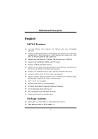
as Windows NT, Windows 2000, Windows ME, Windows XP, LINUX and SCO UNIX. Intel® AC'97 2.2 compatible. High S/N ratio meets PC 99 requirements. 6CH DAC, applicable for leading motherboard chipsets. Line-in phonejack share with rear out. Mic-in phonejack share with Bass & Center. Supports front audio - Biostar P4TGS | P4TGS user's manual - Page 4
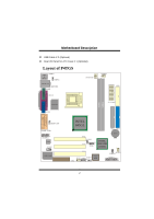
MMootthheerrbbooaarrdd DDeessccrriippttiioonn USB Cable X 2 (Optional) Rear I/O Panel for ATX Case X 1 (Optional) Layout of P4TGS KB & Mouse JKBMS1 1 JUSBV1 USB & LAN JRJ45USB1 JCOM1 JATXPWR2 COM1 JPRNT1 Parallel Port Socket 478 VGA1 ITE I/O JVGA1 SDR1 SDR2 JCFAN1 1 FDD1 JATXPWR1 - Biostar P4TGS | P4TGS user's manual - Page 5
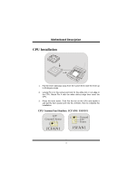
MMootthheerrbbooaarrdd DDeessccrriippttiioonn CPU Installation CPU 1. Pull the lever sideways away from the socket then raise the lever up to 90-degree angle. 2. Locate Pin A in the socket and lock for the white dot or cut edge in the CPU. Match Pin A with the white dot/cut edge then insert the - Biostar P4TGS | P4TGS user's manual - Page 6
MMootthheerrbbooaarrdd DDeessccrriippttiioonn SDR DIMM Modules: SDR1-2 DRAM Access Time: 3.3V Unbuffered PC100/ PC133 Type required. DRAM Type: 64MB/ 128MB/ 256MB/ 512MB DIMM Module (168 pin) DIMM Socket Location SDR 1 SDR 2 SDR Module 64MB/128MB/256MB/512MB *1 64MB/128MB/256MB/512MB *1 Total - Biostar P4TGS | P4TGS user's manual - Page 7
an open Industry Standard Architecture, and it defines a hardware scalable riser card interface, which supports audio, network and modem only. Peripheral Component Interconnect Slots: PCI1-3 This motherboard is equipped with 3 standard PCI slots. PCI stands for Peripheral Component Interconnect, and - Biostar P4TGS | P4TGS user's manual - Page 8
(-) 5 Data (+) 7 Ground 9 Key Pin Assignment 2 +5V 4 Data (-) 6 Data (+) 8 Ground 10 NA 5V/ 5VSB Selection for USB: JUSBV1/ 3/ 4 1 Pin 1-2 on ==> 5V JUSBV1/3/4 Pin 2-3 on ==> 5V_SB Digital Audio Connector: JSPDIF_OUT JSPDIF1 1 Pin Assignment 1 VCC5 2 SPDIFO_OUT 3 GND 6 - Biostar P4TGS | P4TGS user's manual - Page 9
DDeessccrriippttiioonn Front Panel Connector: JPANEL1 PWR_LED SLP ON/OFF IR 2 24 1 23 SPK (+) (-) RST IR HLED SPK ==> Speaker Conn. HLED ==> Hard Driver LED RST ==> Reset Button IR ==> Infrared Conn. SLP ==> Sleep Button PWR_LED ==> Power LED ON/ OFF ==> Power-on Button - Biostar P4TGS | P4TGS user's manual - Page 10
RT Line In 13 LFT Line In 14 LFT Line In Pin 5, 9, 11, 13 are routed to Front Panel Audio Out. Pin 6, 10, 12, 14 are routed from Front Panel Audio Out. Front Panel Audio Connector/ Jumper Block Jumper Setting 1 3 5 7 246 Pin 5 and 6 Pin 9 and 10 9 10 Pin11 and 12 11 12 Pin13 - Biostar P4TGS | P4TGS user's manual - Page 11
MMootthheerrbbooaarrdd DDeessccrriippttiioonn Clear CMOS Jumper: JCMOS1 1 Pin 1-2 on ==> Normal Operation (default) JCMOS1 Pin 2-3 on ==> Clear CMOS Data Back Panel Connectors JKBMS1 JUSBLAN1 PS/2 LAN(Optional) Mouse JPRNT1 Parallel JGAME1 Game Port PS/2 USB Keyboard COM1 JCOM1 VGA1 - Biostar P4TGS | P4TGS user's manual - Page 12
, corriendo a 400 MHz o Fuzzy 533 MHz frecuencia Front Side Bus. Soporta una ranura CNR (solamente de tipo A), y tres ranuras PCI Bus de 32-bit. Compatible con la forma de PC Micro-ATX. Soporta sistemas operativos populares tales como Windows NT, Windows 2000, Windows ME, Windows XP, LINUX - Biostar P4TGS | P4TGS user's manual - Page 13
Memoria Flash Writer para actualización del BIOS X 1 Cable USB X 2 (Opcional) Panel trasero I/O para caja ATX X 1 (Opcional) Disposición del P4TGS Puerto Paralelo JKBMS1 1 JUSBV1 JRJ45USB1 JCOM1 JPRNT1 ITE I/O Socket 478 JATXPWR2 JCFAN1 1 FDD1 JATXPWR1 COM1 SDR1 SDR2 VGA1 JVGA1 Entrada - Biostar P4TGS | P4TGS user's manual - Page 14
MMootthheerrbbooaarrdd DDeessccrriippttiioonn Instalación de la CPU CPU 1. Tire de la palanca del lado del zócalo, luego levante la palanca hasta un ángulo de 90 grados. 2. Sitúe el contacto A del zócalo y busque el punto blanco o corte el borde en la CPU. Empareje el contacto A con el punto - Biostar P4TGS | P4TGS user's manual - Page 15
MMootthheerrbbooaarrdd DDeessccrriippttiioonn Módulos SDR DIMM: SDR1-2 DRAM Tiempo de Acceso: 3.3V Unbuffered PC100/ PC133 Tipo requerido. DRAM Tipo: 64MB/ 128MB/ 256MB/ 512MB Módulo DIMM (168 Contactos) Localización del Zócalo DIMM SDR 1 SDR 2 Módulo SDR 64MB/128MB/256MB/512MB *1 64MB/128MB/ - Biostar P4TGS | P4TGS user's manual - Page 16
CNR1 La especificación CNR es una abierta Industria Estándar de Arquitectura, y define una tarjeta hardware escalable de interface en el que soporta audio, red y módem. Ranura de Interconexión del Componente Periférico: PCI1-3 Ésta placa madre está equipado con 3 ranuras PCI. PCI es la sigla para - Biostar P4TGS | P4TGS user's manual - Page 17
9 Key Contactos 2 4 6 8 10 Asignacion +5V Data (-) Data (+) Ground NA 5V/ 5VSB Selección para USB: JUSBV1/ 3/ 4 1 Contacto 1-2 on ==> 5V JUSBV1/3/4 Contacto 2-3 on ==> 5V_SB Conector Digital de Audio: JSPDIF_OUT JSPDIF_OUT Contactos Asignacion 1 1 VCC5 2 SPDIF_Out 3 GND 15 - Biostar P4TGS | P4TGS user's manual - Page 18
Reinicio ==> Conector Infrarojo SLP ==> Boton de Suspension PWR_LED ==> Corriente LED ON/ OFF ==> Boton de Encendido Subsistema de Audio: JAUDIO1/ JCDIN1 22 14 11 13 11 JAJAUUDDIOIO1 1 JJCCDDIINN11 (Cab(eFzraolndt eAAuuddiiooHFeraodnetar)l)((CCDab-RezOaMl dAe Eudnitora-IdnaHdeeaAduedr - Biostar P4TGS | P4TGS user's manual - Page 19
DDeessccrriippttiioonn 22 14 1 13 JAUDIO1 Contactos 1 3 5 7 9 11 13 Asignacion Contactos Asignacion Entrada del MIC 2 Tierra Corriente del MIC 4 Corriente de Audio RT Salida de Linea 6 RT Salida de Linea Reservado 8 Key LFT Salida de Linea 10 LFT Salida de Linea RT Entrada de - Biostar P4TGS | P4TGS user's manual - Page 20
MMootthheerrbbooaarrdd DDeessccrriippttiioonn Puente de Borrar CMOS: JCMOS1 1 Contacto 1-2 encendido ==> Operacion Normal (default) Contacto 2-3 encendido ==> Borrar Datos CMOS JCMOS1 Conectores del Panel Trasero JKBMS1 RJ45USB1 Raton LAN(Opcional) PS/2 JPRNT1 Paralelo JGAME1_USB1 Puerto de - Biostar P4TGS | P4TGS user's manual - Page 21
MMootthheerrbbooaarrdd DDeessccrriippttiioonn WarpSpeeder Introduction [ WarpSpeeder™ ], a new powerful control utility, features three user-friendly functions including Overclock Manager, Overvoltage Manager, and Hardware Monitor. With the Overclock Manager, users can easily adjust the frequency - Biostar P4TGS | P4TGS user's manual - Page 22
MMootthheerrbbooaarrdd DDeessccrriippttiioonn System Requirement OS Support: Windows 98 SE, Windows Me, Windows 2000, Windows XP DirectX: DirectX 8.1 or above. (The Windows XP operating system includes DirectX 8.1. If you use Windows XP, you do not need to install DirectX 8.1.) Installation 1. - Biostar P4TGS | P4TGS user's manual - Page 23
MMootthheerrbbooaarrdd DDeessccrriippttiioonn 2. When you see the following dialog in setup procedure, it means setup is completed. If the "Launch the WarpSpeeder Tray Utility" checkbox is checked, the Tray Icon utility and [ WarpSpeeder™ ] utility will be automatically and immediately launched - Biostar P4TGS | P4TGS user's manual - Page 24
the screen printed in this user manual will change according to your motherboard on hand. [ WarpSpeeder™ ] includes 1 tray icon and 5 panels: 1. Tray Icon: Whenever the Tray Icon utility is launched, it will display a little tray icon on the right side of Windows - Biostar P4TGS | P4TGS user's manual - Page 25
2. Main Panel If you click the tray icon, [ WarpSpeeder™ ] utility will be invoked. Please refer do the following figure; the utility's first window you will see is Main Panel. Main Panel contains features as follows: a. Display the CPU Speed, CPU external clock, Memory clock, AGP clock, and - Biostar P4TGS | P4TGS user's manual - Page 26
MMootthheerrbbooaarrdd DDeessccrriippttiioonn 3. Voltage Panel Click the Voltage button in Main Panel, the button will be highlighted and the Voltage Panel will slide out to up as the following figure. In this panel, you can decide to increase CPU core voltage and Memory voltage or not. The default - Biostar P4TGS | P4TGS user's manual - Page 27
3MHz button", "-1MHz button", "+1MHz button", and "+3MHz button": provide user the ability to do real-time overclock adjustment. Warning: Manually overclock is potentially dangerous, especially when the overclocking percentage is over 110 %. We strongly recommend you verify every speed you overclock - Biostar P4TGS | P4TGS user's manual - Page 28
MMootthheerrbbooaarrdd DDeessccrriippttiioonn d. "Verify button": User can click this button and [ WarpSpeeder™ ] will proceed a testing for current frequency. If the testing is ok, then the current frequency will be saved into system registry. If the testing fail, system will do a fail-safe - Biostar P4TGS | P4TGS user's manual - Page 29
panel, you can get model name and detail information in hints of all the chipset that are related to overclocking. You can also get the mainboard's BIOS model and the Version number of [ WarpSpeeder™ ] utility. 27 - Biostar P4TGS | P4TGS user's manual - Page 30
MMootthheerrbbooaarrdd DDeessccrriippttiioonn 28 - Biostar P4TGS | P4TGS user's manual - Page 31
MMootthheerrbbooaarrdd DDeessccrriippttiioonn Note: Because the overclock, overvoltage, and hardware monitor features are controlled by several separate chipset, [ WarpSpeeder™ ] divide these features to separate panels. If one chipset is not on board, the correlative button in Main panel will be - Biostar P4TGS | P4TGS user's manual - Page 32
Trouble Shooting PROBABLE SOLUTION No power to the system at all Power light don't * Make sure power cable is securely plugged in illuminate, fan inside on. Indicator light on power supply does not keyboard does not turn turn on * Replace cable * Contact technical support PROBABLE - Biostar P4TGS | P4TGS user's manual - Page 33
Solución de Problemas CAUSA PROBABLE SOLUCIÓN No hay corriente en el sistema. La luz de * Asegúrese que el cable de transmisión esté corriente no ilumina, ventilador dentro de la seguramente enchufado. fuente de alimentación apagada. luz del teclado apagado. Indicador de * Reemplace el cable - Biostar P4TGS | P4TGS user's manual - Page 34
12/06/2002 32
-
 1
1 -
 2
2 -
 3
3 -
 4
4 -
 5
5 -
 6
6 -
 7
7 -
8
-
9
-
10
-
11
-
12
-
13
-
14
-
15
-
16
-
17
-
18
-
19
-
20
-
21
-
22
-
23
-
24
-
25
-
26
-
27
-
28
-
29
-
30
-
31
-
32
-
33
-
34
 |
 |

P
P
P
4
4
4
T
T
T
G
G
G
S
S
S
i
FCC Statement and Copyright
This equipment has been tested and found to comply with the limits of a
Class B digital device, pursuant to Part 15 of the FCC Rules. These limits
are designed to provide reasonable protection against harmful interference
in a residential installation. This equipment generates, uses and can
radiate radio frequency energy and, if not installed and used in
accordance with the instructions, may cause harmful interference to radio
communications. There is no guarantee that interference will not occur in a
particular installation.
The vendor makes no representations or warranties with respect to the
contents here of and specially disclaims any implied warranties of
merchantability or fitness for any purpose. Further the vendor reserves the
right to revise this publication and to make changes to the contents here of
without obligation to notify any party beforehand.
Duplication of this publication, in part or in whole is not allowed without
first obtaining the vendor’s approval in writing.
The content of this user’s is subject to be changed without notice and we
will not be responsible for any mistakes found in this user’s manual. All the
brand and product names are trademarks of their respective companies.