Bosch HDS7152U Installation Instructions
Bosch HDS7152U - Evolution 700 Series Dual Fuel Range Manual
 |
UPC - 825225842675
View all Bosch HDS7152U manuals
Add to My Manuals
Save this manual to your list of manuals |
Bosch HDS7152U manual content summary:
- Bosch HDS7152U | Installation Instructions - Page 1
Installation Instructions Installation et instruction Installation e instrucción Dual-F uel Slide-In Range fr Cuisinièr e mixt e es El combus tible doble liber ta las gamas paradas - Bosch HDS7152U | Installation Instructions - Page 2
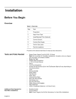
Table of Contents Safety 1 Important Safety Instructions 1 Installation 4 Before You Begin 4 Overview 4 Tools and Parts Needed 4 Parts Included 5 General Information 5 Preparation 5 Installation Procedure 11 Apply Foam Tape 11 Install Backwall Trim 11 Connect Electric 12 Connect Gas - Bosch HDS7152U | Installation Instructions - Page 3
INSTRUCTIONS READ AND SAVE THESE INSTRUCTIONS Important Safety Instructions Related Equipment Safety WARNING: Do not repair or replace any part of the appliance unless specifically recommended in the manuals. Improper installation, service the Safety of Household Electric Ranges • UL 923, The - Bosch HDS7152U | Installation Instructions - Page 4
"for use with ranges" shall be used. • Installer - show the owner the location of the circuit breaker or fuse. Mark it for easy reference. • Important - Save these instructions for the local electrical inspector's use. • Before installing, turn power OFF at the service panel. Lock service panel to - Bosch HDS7152U | Installation Instructions - Page 5
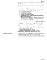
column (34.9Millibars). WARNING: If the information in this manual is not followed exactly, a fire or explosion may result causing instructions. • If you cannot reach your gas supplier, call the fire department. Installation and service must be performed by a qualified installer, authorized service - Bosch HDS7152U | Installation Instructions - Page 6
for Gas Leaks 7. Test the Installation Proceed to the sections that follow for step-by-step instructions. Tools and Parts Needed Additional Parts Needed For Hard Wire Installations • Range Power Supply Cord Kit (240V -30 Amp) Note: Not necessary for Canadian installations; Canadian units are - Bosch HDS7152U | Installation Instructions - Page 7
Parts Included General Information Overall Dimensions Level Preparation Prepare Unit • Anti-Tip Bracket • Foam Tape • unpacking the appliance. Never allow children to play with packaging material. Tip: Place the range on a piece of the cardboard to protect floors. Remove drawer and set aside. 1. - Bosch HDS7152U | Installation Instructions - Page 8
Data Plate" on page 24 for data plate location. We recommend that the range be installed with a power cord set (not supplied). The electrical rating of Ranges." Always use a new power cord. Note: In Canada, the range is shipped from the factory with the range cord already installed. English - Bosch HDS7152U | Installation Instructions - Page 9
Gas Requirements Installation Ranges are dual rated for use on either 120/240 VAC or 120/208 VAC. Check the data plate for the kW rating. Reference the kW rating in the table below to determine amperage requirements. Table 3: Electrical Specifications kW Rating Hz Amps Req'd 120/240V 6.2 120/ - Bosch HDS7152U | Installation Instructions - Page 10
gas shut off valve in an easily accessible location. Make sure all users know where and how to shut off the gas supply to the range. Note: The installer should inform the consumer of the location of the gas shutoff valve. Important note for LP users The - Bosch HDS7152U | Installation Instructions - Page 11
range can also replace a freestanding range. In this case, verify that the opening is at least 30 inches. Figure 6: Cutout Requirements - Replacing a Free-Standing Model the bottom of the cabinet. 1. Instructions were determined using standard American cabinets. dimensions accordingly. English 9 - Bosch HDS7152U | Installation Instructions - Page 12
sheet metal, 0.015 inch stainless steel' or 0.024 inch aluminum or copper. From range walls to adjacent materials: See Figure 7: Cabinet Preparation. No clearance is required from 300 CFM is recommended. The range hood must be installed according to instructions furnished with the hood. English 10 - Bosch HDS7152U | Installation Instructions - Page 13
foam tape to underside of cooktop trim in one continuous piece. Note: This step is only required if the countertop does not connect behind the range (i.e.; when replacing a free-standing range). See "Cabinet Requirements" on page 8 for more information Install 2 screws through holes in trim and in - Bosch HDS7152U | Installation Instructions - Page 14
" on page 16. For installations other than those in Canada, connect the range cord at the terminal block (See next page for detailed instructions). Access the terminal block by removing the cover in the lower right hand corner of the range back panel. Place strain relief in knockout below terminal - Bosch HDS7152U | Installation Instructions - Page 15
this purpose). Use only cord kits rated 125/250 volts (minimum), 30 amperes and labeled "For Use with Ranges". Strain relief provided with cord must be installed per instructions included with cord. Figure 12: Grounding Requirements WARNING: To prevent electrical shock, the grounding prong on the - Bosch HDS7152U | Installation Instructions - Page 16
rotate so that wide end is at top and attach wide end to range through hole below junction box. Attach green wire on top of ground strap Tighten Screw. green ground screw ground strap ground wire Figure 14: Four Wire Range Cord Connection - Ground Strap and Wire 6. Attach red wire, round washer - Bosch HDS7152U | Installation Instructions - Page 17
Installation Three Wire Range Cord Connection The Four Wire Connection (above) is preferred, but where local codes and ordinances permit grounding through neutral and where conversion to four wire - Bosch HDS7152U | Installation Instructions - Page 18
8. Properly secure strain relief. See "Install Strain Relief" on page 12 for detailed instructions. Note: DO NOT plug in range at this time. Connect Gas Supply Shut off main gas supply valve before disconnecting the old range and leave it off until the new hook-up has been completed. Don't forget - Bosch HDS7152U | Installation Instructions - Page 19
manual shutoff valve. 3. Connect flexible metal appliance connector. Plug in Range Cord 1. Make sure circuit breaker is off and then plug range Measure back left corner of range to bottom of cooktop trim. Adjust leveling leg until this height is the same as the corner dimension. 4. Repeat in right - Bosch HDS7152U | Installation Instructions - Page 20
for Proper Installation 1. When properly installed, the cooktop trim around the back of the range will rest lightly on the countertop. Note: When replacing a free-standing model, the backwall trim strip should be flush with the wall. 2. There should not be any gap between the countertop and the - Bosch HDS7152U | Installation Instructions - Page 21
all the way around. 2. Verify that both front legs are resting solidly on the floor. 3. Use a level to verify that the range is level and plumb. 4. Carefully tip range forward to ensure that anti-tip bracket engages and pre- vents tip-over. The gas connection is complete. Proceed to "Test for Gas - Bosch HDS7152U | Installation Instructions - Page 22
for Proper Installation 1. When properly installed, the cooktop trim around the back of the range will rest lightly on the countertop. Note: When replacing a free-standing model, the backwall trim strip should be flush with the wall. 2. There should not be any gap between the countertop and the - Bosch HDS7152U | Installation Instructions - Page 23
under the anti-tip bracket, slide range out, adjust legs and slide back in. Adjust Front of Range for Proper Installation 1. Adjust front 21. Leak testing is to be conducted by the installer according to the instructions given in this section. Note: Be careful not to apply pressure to warming - Bosch HDS7152U | Installation Instructions - Page 24
of the wiring may be reversed. Reversed polarity can damage the range and can result in electrical shock hazard. Immediately switch off too large, contact service. Test flame characteristics on the high setting: 1. Push in and turn the knob to the flame symbol until the burner ignites. 2. Turn knob - Bosch HDS7152U | Installation Instructions - Page 25
Soft Blue Flames: Normal for Natural Gas. If the flame is completely or mostly yellow, verify that the regulator is set for the correct fuel. After adjustment, retest. Some yellow streaking is normal during the initial start-up. Allow unit to operate 4-5 minutes and re-evaluate. Figure 24: Checking - Bosch HDS7152U | Installation Instructions - Page 26
for troubleshooting information. Refer to the Warranty in the Use and Care Manual. To reach a service representative, see the contact information at the front of the manual. Please be prepared with the information printed on your product data plate when calling. The data plate shows the model and - Bosch HDS7152U | Installation Instructions - Page 27
- Bosch HDS7152U | Installation Instructions - Page 28
Table des matières Sécurit 1 Instructions de sécurité importantes 1 Installation 4 Avant de commencer 4 Généralités 4 Outils et Vérifier les fuites de gaz 22 Vérifier l'installation 23 Service 25 Avant d'effectuer un appel de service 25 Plaque signalétique 25 Questions? 1.800.944.2904 www - Bosch HDS7152U | Installation Instructions - Page 29
LIRE ET CONSERVER CES INSTRUCTIONS Instructions de sécurité importantes Sécurité relative à l'équipement AVERTISSEMENT : Ne pas réparer ni remplacer les pièces de l'appareil à moins que cela ne soit spécifiquement recommandé dans les guides. Une installation, un service ou un entretien inad - Bosch HDS7152U | Installation Instructions - Page 30
ANSI/ NFPA 70, dernière édition. (Au Canada, l'installation doit être conforme aux codes d'installation CAN mettre l'alimentation hors circuit au panneau de service, le verrouiller pour éviter la mise de gaz selon les directives données dans ce guide. • L'appareil et sa soupape d'arrêt individuelle - Bosch HDS7152U | Installation Instructions - Page 31
14,0 po C.E. (34,9 millibarres). AVERTISSEMENT : si l'information de ce guide n'est pas suivie exactement, il peut en résulter un incendie ou un instructions du fournisseur de gaz. • Si l'on ne peut rejoindre le fournisseur de gaz, téléphoner au service des incendies. L'installation et le service - Bosch HDS7152U | Installation Instructions - Page 32
Vérifier l'installation Procéder aux sections suivantes pour les instructions étapes par étapes. • Nécessaire d'alimentation de cuisini Remarque : non nécessaire pour les installations canadiennes; les appareils pour le Canada sont déjà doté d'un cordon d'alimentation installé. • Ruban à mesurer • - Bosch HDS7152U | Installation Instructions - Page 33
• Cosses (pour installation à raccordement fixe) Remarque : non nécessaires pour installation au Canada) Généralités Dimensions hors tout Niveau Préparation Préparer l'appareil Tableau 2: Dimensions hors tout Dimension Poids Centimèters Hauteur Largeur Profondeur 36 po 31 po 25 5/8 po 91,44 - Bosch HDS7152U | Installation Instructions - Page 34
(selon les codes locaux). Le nécessaire de cordon d'alimentation doit être marqué (Pour utilisation avec cuisinières). Toujours utiliser un nouveau cordon d'alimentation. Remarque : Au Canada, la cuisinière est expédiée de l'usine avec le cordon déjà en place. Français 6 - Bosch HDS7152U | Installation Instructions - Page 35
électrique de la résidence est adéquat. Dans certains cas, le calibre du câblage de la résidence et l'interrupteur de service doivent être augmentés pour supporter la charge électrique requise par la cuisinière. La plupart des codes de câblages requiert un circuit séparé avec un interrupteur de - Bosch HDS7152U | Installation Instructions - Page 36
Installation La canalisation d'alimentation en gaz et la prise électrique doivent être situées dans la zone ombragée comme à la Figure 4: Emplacement de sortie électrique et canalisationen gaz. Exigences pour les armoires 7 1/2 po (190,5 mm) 3 1/2 po 88,9 mm 4 1/2 po 114,3 mm 4 po (101,6 mm) - Bosch HDS7152U | Installation Instructions - Page 37
Installation . 23 1/16 po (585,4 mm) 30 po (762 mm) Figure 5: Exigences de découpe - installation typique Remarque : La cuisinière à encastrer peut aussi remplacer une cuisinière amovible. Dans ce cas vérifier que l'ouverture a au moins 30 po. 30 po (76,2 cm) min. Figure 6: Exigences de découpe - - Bosch HDS7152U | Installation Instructions - Page 38
moins 4 po. Remarque : Certains finis d'armoires ne peuvent supporter les températures permises par U.L., particulièrement avec four Ceci est plus remarquable avec les armoires laminées. 1.Les instructions sont déterminées en utilisant des armoires standard de type am dimensions en conséquence. - Bosch HDS7152U | Installation Instructions - Page 39
plupart des cuisines, une hotte certifiée ayant une cote de pas moins de 300 pi3/ min est recommandée. La hotte doit être installée selon les instructions fournies avec l'appareil. Français 11 - Bosch HDS7152U | Installation Instructions - Page 40
Installation Procédure d'installation Apposer du ruban mousse Installer la garniture de dosseret Apposer du ruban mousse sur le côté inférieur de la garniture de surface de cuisson en une pièce continue. Remarque : Cette étape est requise seulement si le plan de travail n'est pas relié derrière la - Bosch HDS7152U | Installation Instructions - Page 41
de l'alimentation en gaz" à la page 17. Pour les installations autres qu'au Canada, brancher le cordon de la cuisinière au bloc de bornes. (voir la page tre installé adéquatement. Les modèles varient. Lire attentivement les instructions fournies avec le réducteur de tension. 1. Dans le panneau à - Bosch HDS7152U | Installation Instructions - Page 42
ampères et étiquetés (Pour utilisation avec cuisinière). Le réducteur de tension fourni avec le cordon doit être installé selon les instructions fournies avec le cordon. CONNEXION à 3 FILS CONNEXION à 4 FILS . FIL NOIR FNIELUBTLRAENC FIL ROUGE FIL NOIR NFEILUBTLRAENC FIL ROUGE Connexion de cuisini - Bosch HDS7152U | Installation Instructions - Page 43
Installation 3. Enlever l'écrou supérieur, rondelle étoile et rondelle ronde de chaque tige. Remarque : NE PAS enlever la dernière rondelle ronde, dernier écrou ou fils de câblage interne. 4. Enlever la vis au bas de l'extrémité du conducteur de terre. 5. Enlever le conducteur de terre de la tige - Bosch HDS7152U | Installation Instructions - Page 44
Installation Connexion de cuisinière à 3 fils La connexion à 4 fils est préférable, mais là où les codes et règlements permettent la mise à la terre par le neutre et où la conversion à 4 fils n'est pas pratique, l'appareil peut être branché sur l'alimentation électrique par une connexion à 3 fils. - Bosch HDS7152U | Installation Instructions - Page 45
: Connexion à 3 fils complétée 8. Bien fixer le réducteur de tension. Voir "Installation du réducteur de tension" à la page 13 pour les instructions détaillées. Remarque : NE PAS brancher l'appareil à ce moment. Connexion de l'alimentation en gaz Fermer la soupape d'alimentation en gaz principale - Bosch HDS7152U | Installation Instructions - Page 46
Installation Remarque importantes pour utilisateurs de gaz LP Méthode de connecteur flexible La cuisinière est expédiée de l'usine pour une utilisation avec le gaz naturel. Pour le gaz propane LP, l'appareil doit être converti à l'aide du nécessaire de conversion LP. Si l'on utilise un tuyau rigide - Bosch HDS7152U | Installation Instructions - Page 47
Installation 4. Répéter avec le coin arrière droit. 5. Régler les pieds niveleurs avant afin que le bas de la garniture de surface de cuisson soit ½ po plus haut que la surface du plan de travail correspondante. tiroir Clé pied réglable Figure 21: Régler les pieds niveleurs avant Glisser la cuisiniè - Bosch HDS7152U | Installation Instructions - Page 48
Installation Méthode avec tuyau rigide Français 20 3. S les pieds arrière ne sont pas solidement au sol ou que le pied gauche n'est pas sous le dispositif anti bascule, sortir la cuisinière, régler les pieds et remettre en place. Régler le devant de la cuisinière pour une installation adéquate 1. - Bosch HDS7152U | Installation Instructions - Page 49
Installation La configuration de la connexion du tuyau rigide dépend de l'emplacement du tuyau de gaz. Voir Figure 22: Méthode avec tuyau rigide par exemple. Réglage des pieds niveleurs 1. S'assurer que le coupe-circuit est déclenché, puis brancher le cordon de la cuisinière sur la prise électrique. - Bosch HDS7152U | Installation Instructions - Page 50
de gaz" à la page 22. Vérifier les fuites de gaz La vérification des fuites doit être effectuée par l'installateur selon les instructions données dans ce guide. Remarque : Faire attention à ne pas appliquer de pression sur l'élément du tiroir réchaud pendant la vérification. Français 22 1. Ouvrir - Bosch HDS7152U | Installation Instructions - Page 51
délai de 4 secondes. Une fois les brûleurs allumés, tourner le bouton en position ARRÊT. 4. Vérifier chaque brûleur de cette façon. Téléphoner au service si un brûleur ne s'allume pas. Caractéristiques des flammes au réglage bas : 1. Pousser et tourner le bouton au symbole de flamme jusqu'à ce - Bosch HDS7152U | Installation Instructions - Page 52
de détails. 4. Vérifier chaque brûleur de cette façon. Si la flamme est jaune ou n'entoure pas adéquatement le brûleur, téléphoner au service. Flamme jaune : Réglage nécessaire Pointe jaune sur cône extérieur : Normal pour gaz LP Flamme bleue : Normal pour gaz naturel Si la flamme est jaune - Bosch HDS7152U | Installation Instructions - Page 53
d'utilisation et d'entretien. Consulter la garantie. Pour communiquer avec un représentant de service, voir l'information au début du guide. Avoir l'information imprimée sur la plaque signalétique sous la main avant de téléphoner. La plaque signalétique donne les numéros de modèle - Bosch HDS7152U | Installation Instructions - Page 54
Contenidos Seguridad 1 Instrucciones Importantes de Seguridad 1 Instalación 4 Antes de comenzar 4 Resumen 4 Herramientas y partes que se necesitan 4 Partes incluidas 5 Información general 5 Preparación 5 Procedimiento de Instalación 12 Aplicar cinta de espuma 12 Instalar la moldura de la - Bosch HDS7152U | Installation Instructions - Page 55
repare o reemplace ninguna parte del aparato a menos que se recomienda específicamente en los manuales. La instalación, servicio . Quite la puerta para facilitar el manejo y la instalación. Vea las instrucciones en el manual de uso y cuidado. • La unidad está pesada y requiere al menos de dos - Bosch HDS7152U | Installation Instructions - Page 56
cualquier prueba de presión que excede ½ psi (3.5 kPa). • Se debe aislar el aparato del sistema de tubería de suministro de gas cerrando su válvula manual de cierre de gas durante cualquier prueba de presión del sistema de suministro de gas a presiones de prueba igual a o menor que ½ psi (3.5 kPa - Bosch HDS7152U | Installation Instructions - Page 57
presión de suministro no debe exceder 14.0 pulgadas columna de agua (34.9 milibar). ADVERTENCIA: La falta de observar la información en este manual puede causar un fuego o una explosión, y como resultado daños a la propiedad, lesiones o la muerte. • No guarde o use materiales combustibles, gasolina - Bosch HDS7152U | Installation Instructions - Page 58
Instalación Antes de comenzar Resumen Herramientas y partes que se necesitan Tabla 1: Resumen Paso Tarea 1. Preparación 2. Aplicar cinta de espuma 3. Instalar la moldura de la pared trasera (opcional) 4. Conexión eléctrica 5. Conectar el - Bosch HDS7152U | Installation Instructions - Page 59
• • Instalación Conducto flexible Llave inglesa Nota: No se necesita el kit del cable de alimentación eléctrica con instalaciones permanentes Partes incluidas • Soporte antivolcadura • Cinta de espuma • Moldura de la pared trasera • Tornillos para la moldura de la pared trasera (2) • Terminales - Bosch HDS7152U | Installation Instructions - Page 60
Instalación Quitar la puerta del horno y guardarla a un lado. ADVERTENCIA: Cuando quite la puerta: • Asegúrese que el horno esté frío y que se haya apagado la corriente antes de quitar la puerta. De otro modo puede causar una descarga eléctrica o quemaduras. • La puerta del horno está pesada y frá - Bosch HDS7152U | Installation Instructions - Page 61
Requerimientos de gas Instalación Las estufas funcionan con doble voltaje ya sea con 120/240 VAC o 120/208 VAC. Revise la placa de información para la capacidad en kW. Tome referencia de la capacidad kW en la tabla abajo para determinar los requerimientos del amperaje. Tabla 3: Especificaciones el - Bosch HDS7152U | Installation Instructions - Page 62
Instalación Se deben ubicar la línea de suministro de gas y la tomacorriente eléctrica en el espacio sombreado que se muestra en la Figura 4: Ubicación de la línea de suministro de gas y de la tomacorriente eléctrica. 7 1/2" (190.5 mm) 3 1/2" 88.9 mm 4 1/2" 114.3 mm 4" (101.6 mm) 13 1/8 " (333 - Bosch HDS7152U | Installation Instructions - Page 63
Instalación Permita un mínimo de 30 pulgadas (762 mm) entre los gabinetes donde se va a instalar la estufa. 23 1/16" (585.4 mm) 30" (762 mm) Figura 5: Requerimientos del recorte - instalación típica Nota: La estufa deslizable puede sustituir también a una estufa autoestable. En este caso, verifique - Bosch HDS7152U | Installation Instructions - Page 64
127 mm) arriba del fondo del gabinete. Desde la parrilla a los materiales arriba: Debe haber un espacio libre mínimo de 30 pulgadas entre la parte superior de la superficie de cocinar y el fondo de un gabinete de madera o metal no protegido. Vea Figura 7: Preparación para los gabinetes. 24 pulgadas - Bosch HDS7152U | Installation Instructions - Page 65
Preparar las paredes y los pisos Requerimientos para cubiertas Requerimientos de montaje Instalación El espacio libre desde la parte superior de la estufa a las paredes verticales adyacentes debe ser al menos 4". Nota: El acabado de algunos gabinetes no puede sobrevivir las temperaturas permitidas - Bosch HDS7152U | Installation Instructions - Page 66
Instalación Procedimiento de Instalación Aplicar cinta de espuma Aplique cinta de espuma a la parte inferior de la moldura de la parrilla en una sola pieza continua. Instalar la moldura de la pared trasera Nota: Se requiere este paso solamente - Bosch HDS7152U | Installation Instructions - Page 67
Conexión eléctrica Instalar el prensacables Hay dos conexiones eléctricas posibles: Instalación 1. Cable de la estufa de cuatro hilos 2. Cable de la estufa de tres hilos La conexión con el cable de la estufa de cuatro hilos es el método recomendado, pero donde los códigos locales lo permiten, se - Bosch HDS7152U | Installation Instructions - Page 68
Instalación ADVERTENCIA: Riesgo de una descarga eléctrica o un fuego. El bastidor está conectado a neutral a través de un cable de tierra. Se prohibe la conexión a tierra a través del conductor neutral para instalaciones nuevas con circuito de derivación (1996 NEC), casas rodantes y vehículos - Bosch HDS7152U | Installation Instructions - Page 69
ancho quede arriba y fije el extremo ancho a la estufa a través del agujero abajo de la caja de conexiones. Fije el cable verde en la parte superior de la tira de conexión a tierra. Apriete el tornillo. tornillo verde de conexión a tierra tira de conexión a tierra cable de tierra Figura 14 - Bosch HDS7152U | Installation Instructions - Page 70
, la última tuerca o los cables internos. 4. Fije el cable blanco, la arandela redonda, la arandela de estrella y la tuerca EN ESTE ORDEN en la parte superior de la tira a tierra sobre el poste central. 5. Fije el cable rojo, la arandela redonda, la arandela de estrella y la tuerca EN ESTE ORDEN - Bosch HDS7152U | Installation Instructions - Page 71
de la estufa. Vea Figura 19: Ubicación de la conexión del gas. Se puede acceder a través del panel de acceso del cajón calentador o desde la parte trasera de la estufa. Para alcanzar el panel de acceso, quite el cajón calentador. Figura 19: Ubicación de la conexión del gas 1.Teflón es una - Bosch HDS7152U | Installation Instructions - Page 72
nico de unión de 1/2" o 3/4" en la rosca interna de la válvula manual de cierre. 3. Conecte la manguera flexible de metal del aparato. Enchufar el cable de la esquina trasera izquierda de la abertura desde el piso a la parte superior de la cubierta. 3. Tome medida de la esquina trasera izquierda de - Bosch HDS7152U | Installation Instructions - Page 73
trasera de la estufa para una instalación correcta 1. Cuando quede instalado correctamente, la moldura de la parrilla alrededor de la parte trasera de la estufa descansará ligeramente sobre la cubierta. Nota: Cuando reemplaza un modelo autoestable, la tira de la moldura de la pared trasera debe - Bosch HDS7152U | Installation Instructions - Page 74
Instalación Método con tubo rígido Español 20 3. Cuando las patas traseras no descansen bien en el piso o la pata izquierda no quede debajo del soporte antivolcadura, saque la estufa, ajuste las patas y vuelva a deslizarla en su lugar. Ajustar el frente de la estufa para una instalación correcta 1. - Bosch HDS7152U | Installation Instructions - Page 75
posición Off (Apagado). 2. Alinee la estufa enfrente de la abertura. 3. Tome medida de la esquina trasera izquierda de la abertura desde el piso a la parte superior de la cubierta. 4. Ajuste las patas delanteras de nivelación hasta que el fondo de la moldura de la parrilla quede ½" (13mm) arriba de - Bosch HDS7152U | Installation Instructions - Page 76
trasera de la estufa para una instalación correcta 1. Cuando quede instalado correctamente, la moldura de la parrilla alrededor de la parte trasera de la estufa descansará ligeramente sobre la cubierta. Nota: Cuando reemplace un modelo autoestable, la tira de la moldura de la pared trasera debe - Bosch HDS7152U | Installation Instructions - Page 77
Instalación 3. Revise si hay fugas. Burbujas que aparecen alrededor de las conexiones indican una fuga. 4. En caso que se presente una fuga, cierre la válvula de gas de la línea de suministro y apriete todas las conexiones. 5. Vuelva a probar si hay fugas. Vuelva a abrir la válvula de cierre de gas - Bosch HDS7152U | Installation Instructions - Page 78
Instalación Probar las características de llamas con alto calor: 1. Empuje y gire la perilla al símbolo de la llama hasta encender el quemador. 2. Gire la perilla al ajuste de calor alto. 3. Verifique que la llama: • esté fija (No se debe levantar la llama o soplar hacia fuera del quemador. Debe - Bosch HDS7152U | Installation Instructions - Page 79
de uso y cuidado. Para hablar con un representante de servicio, vea la información de contacto al principio del manual. Por favor, tenga a la mano la información impresa en la placa de información de su producto cuando llame. La placa con información indica el número - Bosch HDS7152U | Installation Instructions - Page 80
5551 McFadden Avenue, Huntington Beach, CA 92649 • 800-944-2904 • www.boschappliances.com 9000135014 • 5V0AGF • Rev. D • 05/07 © BSH Home Appliances Corporation, 2007 • All rights reserved Litho in USA
-
 1
1 -
 2
2 -
 3
3 -
 4
4 -
 5
5 -
 6
6 -
 7
7 -
8
-
9
-
10
-
11
-
12
-
13
-
14
-
15
-
16
-
17
-
18
-
19
-
20
-
21
-
22
-
23
-
24
-
25
-
26
-
27
-
28
-
29
-
30
-
31
-
32
-
33
-
34
-
35
-
36
-
37
-
38
-
39
-
40
-
41
-
42
-
43
-
44
-
45
-
46
-
47
-
48
-
49
-
50
-
51
-
52
-
53
-
54
-
55
-
56
-
57
-
58
-
59
-
60
-
61
-
62
-
63
-
64
-
65
-
66
-
67
-
68
-
69
-
70
-
71
-
72
-
73
-
74
-
75
-
76
-
77
-
78
-
79
-
80
 |
 |

Installation Instructions
Installation et instruction
Installation e instrucción
Dual-F uel Slide-In Range
fr
Cuisinière mixte
es
El combus tible doble liber ta las gamas paradas