Bosch LTC 1461-21 Installation Manual
Bosch LTC 1461-21 Manual
 |
View all Bosch LTC 1461-21 manuals
Add to My Manuals
Save this manual to your list of manuals |
Bosch LTC 1461-21 manual content summary:
- Bosch LTC 1461-21 | Installation Manual - Page 1
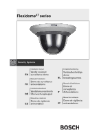
FlexidomeXT series Installation manual Vandal resistant EN surveillance dome Manuel d'installation Dôme de surveillance FR antivandalisme Installationshandbuch Vandalismusresistente DE Überwachungskuppel Manual de instalación Domo de vigilancia ES antivandálico Installatiehandleiding - Bosch LTC 1461-21 | Installation Manual - Page 2
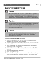
FlexidomeXT | Installation Manual EN | 2 SAFETY PRECAUTIONS Danger The lightning flash with arrowhead is intended to alert the user to the presence of important operating and maintenance (servicing) instructions in the literature accompanying the appliance. Caution To reduce the risk of electric - Bosch LTC 1461-21 | Installation Manual - Page 3
the apparatus. 9. Only use attachments/accessories specified by the manufacturer. 10. Unplug this apparatus during lightning storms or when unused for long periods of time. 11. Refer all servicing to qualified service personnel. Servicing is required when the apparatus has been damaged in any way - Bosch LTC 1461-21 | Installation Manual - Page 4
FlexidomeXT | Installation Manual EN | not installed and used in accordance with the instructions, may cause harmful interference to radio communications. limits. Note Any change or modification not expressly approved by Bosch of the equipment authorization could void the user's authority to - Bosch LTC 1461-21 | Installation Manual - Page 5
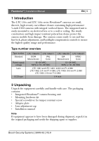
voltage Lens CCD type LTC 136x/10 CCIR Monochrome LTC 146x/11 PAL Color LTC 136x/20 EIA Monochrome LTC 146x/21 NTSC Color 12~24 VAC, 50Hz or 12~33 VDC 12~24 VAC, 60Hz or 12~33 VDC LTC 1361 and LTC 1461: 2.8-6 mm F1.4-360 LTC 1462: 2-4 mm F1.4-360; LTC 1463: 3-6 mm F1.2-360 LTC 1464: 4-9 mm F1 - Bosch LTC 1461-21 | Installation Manual - Page 6
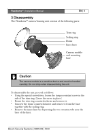
FlexidomeXT | Installation Manual EN | 6 3 Disassembly The FlexidomeXT camera/housing unit consists of the following parts: Trim ring Sealing ring Dome Inner liner Camera module and mounting base Caution The camera and remove it. • Unscrew the dome counterclockwise and remove it from the base - Bosch LTC 1461-21 | Installation Manual - Page 7
service personnel in accordance with the National Electrical Code or applicable local codes. If the connection is from the side, use the optional raised mounting base (LTC 1347) and mount the FlexidomeXT and use them to temporarily hang the camera while the connections are made. The following - Bosch LTC 1461-21 | Installation Manual - Page 8
FlexidomeXT | Installation Manual Figure 4-2 Rear connection - weak surface Wires Thin surface (for example, a suspended ceiling) Four screws (M5, not supplied) EN | 8 Adapter plate Mounting base Figure 4-3 Connection to - Bosch LTC 1461-21 | Installation Manual - Page 9
FlexidomeXT | Installation Manual Figure 4-4 Raised mounting - side connection Solid surface (four pre-drilled 8mm holes) Four screws (supplied) Four screws (M5, supplied) EN | 9 Conduit grommet Wires Raised mounting base (LTC 1347/00) Camera unit and base Figure 4-5 Raised mounting - rear - Bosch LTC 1461-21 | Installation Manual - Page 10
FlexidomeXT | Installation Manual EN | 10 Raised mounting - side connection When using the raised mounting base with a side connection: • Remove the cap cable entry, use round cables of between 5 and 6 mm (0.2 - 0.24 inch) for power and video connection. Bosch Security Systems | 2005-02 | V2.0 - Bosch LTC 1461-21 | Installation Manual - Page 11
FlexidomeXT | Installation Manual EN | 11 the cable connections. • Connect the BNC connector of the camera module to the video coax cable. • Connect the stripped power wires AC supply try to maintain a consistent wiring polarity in multiple camera systems to help avoid rolling when switching. • Push the - Bosch LTC 1461-21 | Installation Manual - Page 12
FlexidomeXT | Installation Manual EN | 12 Setting up the camera You may connect a monitor to the miniature 2.5 mm jack on the printed circuit board cover to help set up the camera. This jack provides a composite video signal, via the optional cable S1460 (2.5 mm plug to BNC female). Focus Focal - Bosch LTC 1461-21 | Installation Manual - Page 13
FlexidomeXT | Installation Manual circuit board. Camera positioning The physical default position of the camera is that camera. The camera module position can be adjusted along three axes. When adjusting the camera thumbscrews, position camera, then gently tighten thumbscrews to secure camera. • To - Bosch LTC 1461-21 | Installation Manual - Page 14
FlexidomeXT | Installation Manual EN | 14 Focal length and focus Before adjusting, place the adjustment cap on the lens to ensure that the image sharpness is the same as when the dome from the monitoring jack. Closing the unit When the camera position is set and all adjustments have been made, - Bosch LTC 1461-21 | Installation Manual - Page 15
Impact protection LTC 136x/10 LTC 146x/11 LTC 136x/20 LTC 146x/21 CCIR Monochrome PAL Color EIA Monochrome NTSC Color 12-24 VAC, 50Hz or 12-33 VDC 12-24 VAC, 60Hz or 12-33 VDC LTC 1361 and LTC 1461: 2.8-6 mm F1.4-360 LTC 1462: 2-4mm F1.4-360; LTC 1463: 3-6 mm F1.2-360 LTC 1364 and LTC 1464 - Bosch LTC 1461-21 | Installation Manual - Page 16
FlexidomeXT | Installation Manual Dimensions (mm) Figure 6-1 FlexidomeXT (4.65") 118 EN | 16 (4.65") 118 (0.77") (0.35") (2.28") 58 20 9 93 (3.66") 144 (5.67") Bosch Security Systems | 2005-02 | V2.0 - Bosch LTC 1461-21 | Installation Manual - Page 17
FlexidomeXT | Installation Manual Figure 6-2 FlexidomeXT with LTC 1347 mounting base (2.2") 56 EN | 17 (1.42") 3 6 11 8 (4.65") 87 (3.43") 3 0 (1.18") 146 (5.75") Bosch Security Systems | 2005-02 | V2.0 - Bosch LTC 1461-21 | Installation Manual - Page 18
FlexidomeXT | Installation Manual EN | 18 Bosch Security Systems | 2005-02 | V2.0 - Bosch LTC 1461-21 | Installation Manual - Page 19
Sicherheitssysteme GmbH Ludwig-Bölkow-Allee 85521 Ottobrunn Germany www.bosch-sicherheitssysteme.de Bosch Security Systems B.V. P.O. Box 80002 5600 JB Eindhoven The Netherlands www.boschsecuritysystems.com © 2005 Bosch Security Systems B.V. Subject to change. Printed in Portugal. 3122 165 23212
-
 1
1 -
 2
2 -
 3
3 -
 4
4 -
 5
5 -
 6
6 -
 7
7 -
8
-
9
-
10
-
11
-
12
-
13
-
14
-
15
-
16
-
17
-
18
-
19
 |
 |
Flexidome
XT
series
Installatiehandleiding
Vandaalbestendige
dome-
bewakingscamera
Manuale d'installazione
Dome di
sorveglianza
Antivandalismo
Manual de instalação
Dome de vigilância
antivandalismo
NL
IT
PT
Installation manual
Vandal resistant
surveillance dome
Manuel d'installation
Dôme de surveillance
antivandalisme
Installationshandbuch
Vandalismusresistente
Überwachungskuppel
Manual de instalación
Domo de vigilancia
antivandálico
EN
FR
DE
ES