Bosch UML-100-90 User Manual
Bosch UML-100-90 Manual
 |
View all Bosch UML-100-90 manuals
Add to My Manuals
Save this manual to your list of manuals |
Bosch UML-100-90 manual content summary:
- Bosch UML-100-90 | User Manual - Page 1
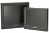
Small Size LCD/LED Monitors UML-080-90 | UML-082-90 | UML-100-90 | UML-102-90 en User Manual - Bosch UML-100-90 | User Manual - Page 2
- Bosch UML-100-90 | User Manual - Page 3
Small Size LCD/LED Monitors Table of Contents Table of Contents | en 3 1 Safety 5 1.1 Important safety instructions 5 1.2 Safety precautions 8 1.3 Important notices 8 1.4 Customer Support and Service 15 2 Unpacking 17 2.1 Parts List 17 3 Exploded View 18 4 Description 21 - Bosch UML-100-90 | User Manual - Page 4
7.1 Power Consumption 7.2 LED Indicator 8 Troubleshooting 9 Maintenance 10 10.1 10.2 Technical Specifications UML-080-90/UML-100-90 UML-082-90/UML-102-90 Small Size LCD/LED Monitors 34 36 36 36 37 38 39 39 40 F.01U.134.499 | 1.0 | 2009.07 User Manual Bosch Security Systems, Inc. - Bosch UML-100-90 | User Manual - Page 5
Monitors 1 Safety Safety | en 5 1.1 Important safety instructions Read, follow, and retain for future reference all of the following safety instructions. Heed all warnings on the unit and in the operating instructions and Bosch Security Systems, Inc. User Manual F.01U.134.499 | 1.0 | 2009.07 - Bosch UML-100-90 | User Manual - Page 6
may expose you to dangerous voltage or other hazards. Refer all servicing to qualified service personnel. 13. Damage requiring service - Unplug the unit from the main AC power source and refer servicing to qualified service F.01U.134.499 | 1.0 | 2009.07 User Manual Bosch Security Systems, Inc. - Bosch UML-100-90 | User Manual - Page 7
LCD/LED Monitors Safety | en follows the operating instructions. 14. Replacement parts - Be sure the service technician uses replacement Bosch, could void the warranty or, in the case of an authorization agreement, authority to operate the equipment. Bosch Security Systems, Inc. User Manual - Bosch UML-100-90 | User Manual - Page 8
Size LCD/LED Monitors 1.2 Safety unit combination to overturn. Mount the unit per the manufacturer's instructions. All-pole power switch - Incorporate an all-pole power the building.If it is needed to open the housing for servicing and/or other activities, use this all-pole switch as the - Bosch UML-100-90 | User Manual - Page 9
Small Size LCD/LED Monitors Safety | en 9 Coax grounding No.70, provides information regarding proper grounding of the mount and supporting structure, grounding of the coax to a discharge unit, size electrostatic discharge. Bosch Security Systems, Inc. User Manual F.01U.134.499 | 1.0 | 2009.07 - Bosch UML-100-90 | User Manual - Page 10
en | Safety Small Size LCD/LED Monitors NOTE: Wear required grounded wrist straps protection, must be in accordance with NEC725 and NEC800 (CEC Rule 16-224 and CEC Section 60). Permanently connected equipment - Incorporate F.01U.134.499 | 1.0 | 2009.07 User Manual Bosch Security Systems, Inc. - Bosch UML-100-90 | User Manual - Page 11
Monitors proper ventilation or adhering to the manufacturer's instructions. The equipment must not exceed its maximum Bosch Security Systems recommends multiple, redundant recording systems, and a procedure to back up all analog and digital information. Bosch Security Systems, Inc. User Manual - Bosch UML-100-90 | User Manual - Page 12
Monitors complies with part 15 of the FCC Rules. Operation is subject to the following pursuant to Part 15 of the FCC Rules and ICES-003 of Industry Canada. accordance with the instruction manual, may cause harmful Identify and Resolve Radio-TV Interference Problems. This booklet is available from - Bosch UML-100-90 | User Manual - Page 13
Monitors Safety | en 13 Informations FCC et ICES (modèles utilisés aux États-Unis et au Canada uniquement) Ce produit est conforme aux normes FCC partie 15. la mise en service aux instructions, TV Interference Problems (Comment Bosch Security Systems, Inc. User Manual F.01U.134.499 | 1.0 | 2009.07 - Bosch UML-100-90 | User Manual - Page 14
14 en | Safety Small Size LCD/LED Monitors Disclaimer Underwriter Laboratories Inc. ("UL") has not tested the SECURITY OR SIGNALING-RELATED FUNCTIONS OF THIS PRODUCT. Copyright This manual is the intellectual property of Bosch Security Systems and is protected by copyright. All rights reserved - Bosch UML-100-90 | User Manual - Page 15
or discrepancies between the user guide and the product described. 1.4 Customer Support and Service If this unit needs service, contact the nearest Bosch Security Systems Service Center for authorization to return and shipping instructions. Service Centers USA Repair CenterTelephone: 800 - Bosch UML-100-90 | User Manual - Page 16
| Safety Small Size LCD/LED Monitors Asia Region Repair Center Telephone: 65 63522776 Fax: 65 63521776 E-mail: [email protected] Customer Service Telephone: 86 (0) 756 7633117 or 86 (0) 756 7633121 Fax: 86 (0) 756 7631710 E-mail: [email protected] Warranty and more information - Bosch UML-100-90 | User Manual - Page 17
are missing, notify your Bosch Security Systems Sales or Customer Service Representative. The original service. Save it for possible future use. 2.1 Parts List Quantity 1 1 1 2 1 1 Description Color LCD Flat Panel Monitor Installation Manual (printed booklet, English version) Installation manual - Bosch UML-100-90 | User Manual - Page 18
18 en | Exploded View 3 Exploded View Small Size LCD/LED Monitors Figure 3.1 Front Panel Ref. Button 1 Speaker 2 Input Description Generate sounds from the input audio Power On (green) OSD. Power Off, Standby (red) F.01U.134.499 | 1.0 | 2009.07 User Manual Bosch Security Systems, Inc. - Bosch UML-100-90 | User Manual - Page 19
LCD/LED Monitors Exploded View | en 19 Figure 3.2 Rear Panel (UML-080-90, UML-082-90) Ref Connector 1 Audio In (for external audio) 2 AV1 In 3 AV1 Out 4 AV2 In 5 AV2 Out 6 VGA In Ref Connector 7 S-Video In 8 12 VDC In 9 Adjustable Stand 10 Trigger Input 11 RS-232 In (for firmware update) Bosch - Bosch UML-100-90 | User Manual - Page 20
Rear Panel (UML-100-90, UML-102-90) Ref Connector 1 Audio In (for external audio) 2 AV1 In 3 AV1 Out 4 AV2 In 5 AV2 Out 6 VGA In Ref Connector 7 S-Video In 8 12 VDC In 9 Adjustable Stand 10 Trigger Input 11 RS-232 In (for firmware update) F.01U.134.499 | 1.0 | 2009.07 User Manual Bosch Security - Bosch UML-100-90 | User Manual - Page 21
models (UML-082-90, UML-102- 90) or CCFL models (UML-080-90, UML-100-90) - NTSC/PAL Auto-Detect - VGA Input - 640 x 480 - 800 x 600 - 1024 x 768 - Composite Video Input - Y/C Input (S-Video) - Trigger input - Multi-language On-screen Display (OSD) Bosch Security Systems, Inc. User Manual F.01U - Bosch UML-100-90 | User Manual - Page 22
/60 Hz UML-082-90 120/230 VAC 50/60 Hz UML-102-90 120/230 VAC 50/60 Hz Voltage Power at Rated Sync Format Range Voltage 100 to 240 V < 35 W NTSC/PAL 100 to 240 V < 35 W NTSC/PAL 100 to 240 V < 35 W NTSC/PAL 100 to 240 V < 35 W NTSC/PAL F.01U.134.499 | 1.0 | 2009.07 User Manual Bosch - Bosch UML-100-90 | User Manual - Page 23
Small Size LCD/LED Monitors Installing the Monitor | en 23 5 Installing the Monitor This chapter outlines the procedures to install the UML-080-90, UML-100-90, UML-082-90 or the UML-102-90 Monitor. A qualified service person should install the monitor and adhere to all local codes. 5.1 - Bosch UML-100-90 | User Manual - Page 24
operating in a single connection mode (see Figure 5.5). If a cable is also connected to the output connector, the video signal can be passed on to another monitor connected to it via the passive loop-through function. F.01U.134.499 | 1.0 | 2009.07 User Manual Bosch Security Systems, Inc. - Bosch UML-100-90 | User Manual - Page 25
Monitors Installing the Monitor | en 25 Up to three (3) monitors may be connected in this manner (see Figure 5.6). Note: To select between AV1 and AV2, press Input (see Figure 3.1, Item 2) located on the front of the monitor . 5.4 Connecting the Y/C (S-Video) Signal to the Monitor Monitor - Bosch UML-100-90 | User Manual - Page 26
the Monitor Small Size LCD/LED Monitors 5.6 Connecting the PC Signal to the Monitor You can connect a PC signal to the monitor using Sync 15 SCL (for DDC) 5.7 Single / Multiple Monitor Configuration Figure 5.5 Single Monitor Configuration Ref Description Ref Description 1 Video Camera 3 AV1 - Bosch UML-100-90 | User Manual - Page 27
Small Size LCD/LED Monitors Installing the Monitor | en 27 Figure 5.6 Multiple Monitor Configuration Ref Description 1 Video Camera 2 AV1 In 3 AV1 Out Bosch Security Systems, Inc. User Manual F.01U.134.499 | 1.0 | 2009.07 - Bosch UML-100-90 | User Manual - Page 28
Monitor Small Size LCD/LED Monitors 6 Navigating the Monitor 6.1 Navigating the Front Panel Use the front panel to make any necessary OSD adjustments to the UML-080-90, UML-100-90, UML-082-90 or the UML-102-90 (red) F.01U.134.499 | 1.0 | 2009.07 User Manual Bosch Security Systems, Inc. - Bosch UML-100-90 | User Manual - Page 29
Small Size LCD/LED Monitors Navigating the Monitor | en 29 6.2 Navigating the Monitor On-screen Display (OSD) The UML-080-90, UML-100-90, UML-082-90 and the UML-10290 have two (2) modes: Video again to exit the OSD menu bar. Bosch Security Systems, Inc. User Manual F.01U.134.499 | 1.0 | 2009.07 - Bosch UML-100-90 | User Manual - Page 30
settings. 6.4 Custom Menu To access the Custom menu, press the Menu button on the front panel of the monitor. Next, press the Input button and then press the up and down buttons to select a submenu. Press to exit the OSD. F.01U.134.499 | 1.0 | 2009.07 User Manual Bosch Security Systems, Inc. - Bosch UML-100-90 | User Manual - Page 31
Small Size LCD/LED Monitors Navigating the Monitor | en 31 Custom 100). Adjusts the overall intensity of the screen (range 0-100). Adjusts the tint of the picture (range 0-100). NTSC only. Adjusts the sharpness level for video performance (range 0-100). Bosch Security Systems, Inc. User Manual - Bosch UML-100-90 | User Manual - Page 32
To access the Picture / Sound menu, press the Menu button on the front panel of the monitor, then press the up and down buttons to select the Picture / Sound icon. Press the Input :Menu Table 6.4 Picture/Sound Menu (PC Mode) F.01U.134.499 | 1.0 | 2009.07 User Manual Bosch Security Systems, Inc. - Bosch UML-100-90 | User Manual - Page 33
. Auto Adjust: Auto synchronizes screen to graphics adaptor. Manual choices are: Phase (range 0-100), H-Phase (range 0-100), VPhase (range 0-100) and Frequency (range 0-100). 3D Comb Enables or disables the 3D comb filter. Bosch Security Systems, Inc. User Manual F.01U.134.499 | 1.0 | 2009.07 - Bosch UML-100-90 | User Manual - Page 34
Menu To access the Setup menu, press the Menu button on the front panel of the monitor, then press the up and down buttons to select the Setup icon. Press the Input loss is detected. Enables or disables the Key Lock function. F.01U.134.499 | 1.0 | 2009.07 User Manual Bosch Security Systems, Inc. - Bosch UML-100-90 | User Manual - Page 35
by the Trigger Input function) is displayed. Once the time expires, the monitor will automatically switch back to the last viewed input. Trigger Option: sets the buttons until the monitor displays the Key Unlocked message. Bosch Security Systems, Inc. User Manual F.01U.134.499 | 1.0 | 2009.07 - Bosch UML-100-90 | User Manual - Page 36
Monitors 7 Power Management These monitors vertical, or a sync signal. The monitor enters an appropriate mode through identifying monitor is comprised of these stages: Mode ON STANDBY ACTIVE OFF LED Color Monitor UNSUPPORTED MODE Green circuitry in the monitor shuts down. Normal operation but - Bosch UML-100-90 | User Manual - Page 37
Monitors Troubleshooting | en 37 8 Troubleshooting Problem Solution No image displayed on screen - Check that the power cord of the monitor either a resolution or timing mode Range" is displayed that is not supported by the monitor. Change the PC timing mode to one of the valid combinations - Bosch UML-100-90 | User Manual - Page 38
38 en | Maintenance Small Size LCD/LED Monitors 9 Maintenance To clean the LCD panel, wipe off water droplets or oil immediately with these materials may permanently damage the polarizer due to a chemical reaction. F.01U.134.499 | 1.0 | 2009.07 User Manual Bosch Security Systems, Inc. - Bosch UML-100-90 | User Manual - Page 39
Small Size LCD/LED Monitors Technical Specifications | en 39 10 Technical Specifications 10.1 UML-080-90/UML-100-90 Model LCD Specifications LCD Type Backlight Type Pixel Pitch (H x V) Brightness Contrast Ratio Response Time Resolution (H x V) Frequency UML-080-90 8.4 in. Digital LCD CCFL 0.213 - Bosch UML-100-90 | User Manual - Page 40
x V) 170.4 x 127.8 mm Packing Dimensions 503 x 349 x 343 mm 211.2 x 158.4 mm 503 x 349 x 343 mm Weight Electric Ratings (19.8 x 13.7 x 13.5 in.) 1.20 kg (2.65 lb) 12 VDC, 2.5 A (19.8 x 13.7 x 13.5 in.) 1.59 kg (3.51 lb) 12 VDC, 2.5 A F.01U.134.499 | 1.0 | 2009.07 User Manual Bosch Security - Bosch UML-100-90 | User Manual - Page 41
- Bosch UML-100-90 | User Manual - Page 42
Bosch Security Systems, Inc. 850 Greenfield Road Lancaster, PA 17601 U.S.A. Telephone +1 800-566-2283 Fax +1 800-366-1329 www.boschsecurity.com © Bosch Security Systems, Inc., 2009, Data subject to change.
-
 1
1 -
 2
2 -
 3
3 -
 4
4 -
 5
5 -
 6
6 -
 7
7 -
8
-
9
-
10
-
11
-
12
-
13
-
14
-
15
-
16
-
17
-
18
-
19
-
20
-
21
-
22
-
23
-
24
-
25
-
26
-
27
-
28
-
29
-
30
-
31
-
32
-
33
-
34
-
35
-
36
-
37
-
38
-
39
-
40
-
41
-
42
 |
 |

Small Size LCD/LED Monitors
UML-080-90 | UML-082-90 | UML-100-90 | UML-102-90
en
User Manual