Brother International 8350P Service Manual
Brother International 8350P - FAX B/W Laser Manual
 |
View all Brother International 8350P manuals
Add to My Manuals
Save this manual to your list of manuals |
Brother International 8350P manual content summary:
- Brother International 8350P | Service Manual - Page 1
FACSIMILE EQUIPMENT SERVICE MANUAL MODEL: FAX4750/5750 MFC8300/8600/8700 FAX8350P/8750P MFC9650 - Brother International 8350P | Service Manual - Page 2
© Copyright Brother 2000 All rights reserved. No part of this publication may be reproduced in any form or by any means without permission in writing from the publisher. Specifications are subject to change without notice. All products and company names mentioned in this manual are trademarks or - Brother International 8350P | Service Manual - Page 3
VI. GENERAL DESCRIPTION INSTALLATION THEORY OF OPERATION DISASSEMBLY/REASSEMBLY AND LUBRICATION MAINTENANCE MODE ERROR INDICATION AND TROUBLESHOOTING Appendix 1. Appendix 2. EEPROM Customizing Codes Circuit Diagrams This manual describes the models and their versions to be destined for major - Brother International 8350P | Service Manual - Page 4
Class 1 laser product under the US Department of Health and Human Services (DHHS) the laser beam cannot escape from the machine during any phase of user laser products marketed in the United States. The label for Chinese products MANUFACTURED: JULY 1999 C BROTHER CORP. (ASIA) LTD. BROTHER - Brother International 8350P | Service Manual - Page 5
CHAPTER I. GENERAL DESCRIPTION - Brother International 8350P | Service Manual - Page 6
CHAPTER I. GENERAL DESCRIPTION CONTENTS 1. EQUIPMENT OUTLINE I-1 1.1 External Appearance and Weight I-1 1.2 Components I-1 2. SPECIFICATIONS I-2 - Brother International 8350P | Service Manual - Page 7
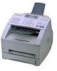
1. EQUIPMENT OUTLINE 1.1 External Appearance and Weight The figure below shows the equipment appearance and approximate dimensions. Weight: Machine proper Machine (incl. drum unit & toner cartridge) In package w/o 2nd cassette 10.5 kg 12.0 kg 16.5 kg w/ 2nd cassette 14.0 kg 15.5 kg 22.0 kg 1.2 - Brother International 8350P | Service Manual - Page 8
2. SPECIFICATIONS Model GENERAL Print Engine Modem Speed (bps) Transmission Speed (sec.) ITU-T Group Coding Method Input/Output Width ADF (pages) LCD Size On-Screen Programming Backup Clock Memory Capacity (MB) Backup Memory Optional Memory Color Standby Mode PC-Fax Protocol Compliance Simultaneous - Brother International 8350P | Service Manual - Page 9
Model GENERAL Print Engine Modem Speed (bps) Transmission Speed (sec.) ITU-T Group Coding Method Input/Output Width ADF (pages) LCD Size On-Screen Programming Backup Clock Memory Capacity (MB) Backup Memory Optional Memory Color Standby Mode PC-Fax Protocol Compliance Simultaneous Operation Data - Brother International 8350P | Service Manual - Page 10
Model GENERAL Print Engine Modem Speed (bps) Transmission Speed (sec.) ITU-T Group Coding Method Input/Output Width ADF (pages) LCD Size On-Screen Programming Backup Clock Memory Capacity (MB) Backup Memory Optional Memory Color Standby Mode PC-Fax Protocol Compliance Simultaneous Operation Data - Brother International 8350P | Service Manual - Page 11
Model GENERAL Print Engine Modem Speed (bps) Transmission Speed (sec.) ITU-T Group Coding Method Input/Output Width ADF (pages) LCD Size On-Screen Programming Backup Clock Memory Capacity (MB) Backup Memory Optional Memory Color Standby Mode PC-Fax Protocol Compliance Simultaneous Operation Data - Brother International 8350P | Service Manual - Page 12
Activation Multi-Resolution Transmission Multi Transmission Next-Fax Reservation Delayed Timer Polling Quick Scan (Memory Transmission) Broadcasting Batch Transmission Auto Reduction Out-of-Paper Reception (Brother #1 Chart) Dual Access ECM (Error Correction Mode) ITU SUB Addressing Group Dial Re - Brother International 8350P | Service Manual - Page 13
Activation Multi-Resolution Transmission Multi Transmission Next-Fax Reservation Delayed Timer Polling Quick Scan (Memory Transmission) Broadcasting Batch Transmission Auto Reduction Out-of-Paper Reception (Brother #1 Chart) Dual Access ECM (Error Correction Mode) ITU SUB Addressing Group Dial Re - Brother International 8350P | Service Manual - Page 14
Multi-Resolution Transmission Multi Transmission Next-Fax Reservation Delayed Timer Polling Quick Scan (Memory Transmission) Broadcasting Batch Transmission Auto Reduction Out-of-Paper Reception (Brother #1 Chart) (ITU-T Chart) Dual Access ECM (Error Correction Mode) ITU SUB Addressing Group Dial Re - Brother International 8350P | Service Manual - Page 15
Fax Reservation Delayed Timer Polling Quick Scan (Memory Transmission) Broadcasting Batch Transmission Auto Reduction Out-of-Paper Reception (ITU-T Chart) Dual Access ECM (Error Correction Mode Approx. 2 sec/page (A4, std. resolution) Yes (182 locations) Yes Yes Up to 130 pages Yes Yes Yes ( - Brother International 8350P | Service Manual - Page 16
Capacity (sheets) Standard Print Language Emulation Resident Fonts Fonts Disk Based Paper Handling Size Manual Feed Slot Other Paper Type Sheet Weight (Paper Cassette) (Manual Slot) Printer Driver Utility Software Toner Life (High Yield : TN-430) (Standard Yield : TN-460) Drum Life (DR400) Interface - Brother International 8350P | Service Manual - Page 17
(sheets) Standard Print Language Emulation Resident Fonts Fonts Disk Based Paper Handling Size Manual Feed Slot Other Paper Type Sheet Weight (Paper Cassette) (Manual Slot) Printer Driver Utility Software Toner Life (High Yield : TN-430) (Standard Yield : TN-460) Drum Life (DR400) Interface - Brother International 8350P | Service Manual - Page 18
(sheets) Standard Print Language Emulation Resident Fonts Fonts Disk Based Paper Handling Size Manual Feed Slot Other Paper Type Sheet Weight (Paper Cassette) (Manual Slot) Printer Driver Utility Software Toner Life (High Yield : TN-430) (Standard Yield : TN-460) Drum Life (DR400) Interface - Brother International 8350P | Service Manual - Page 19
(sheets) Standard Print Language Emulation Resident Fonts Fonts Disk Based Paper Handling Size Manual Feed Slot Other Paper Type Sheet Weight (Paper Cassette) (Manual Slot) Printer Driver Utility Software Toner Life (High Yield : TN-430) (Standard Yield : TN-460) Drum Life (DR400) Interface - Brother International 8350P | Service Manual - Page 20
Time OGM MC/MC Pro/Paging Fax & Voice Mail Box Fax- & Voice-on-Demand VIDEO CAPTURE Video Capture Video Print Video Format BUNDLED SOFTWARE For Windows Printer Driver (Brother) Viewer (ScanSoft) TWAIN (Brother) PC Fax (SMSI)*3 For iMAC Printer Driver (Brother) Viewer (InfoWAVE) TWAIN (TII) PC - Brother International 8350P | Service Manual - Page 21
Time OGM MC/MC Pro/Paging Fax & Voice Mail Box Fax- & Voice-on-Demand VIDEO CAPTURE Video Capture Video Print Video Format BUNDLED SOFTWARE For Windows Printer Driver (Brother) Viewer (ScanSoft) TWAIN (Brother) PC Fax (SMSI)*3 For iMAC Printer Driver (Brother) Viewer (InfoWAVE) TWAIN (TII) PC - Brother International 8350P | Service Manual - Page 22
Time OGM MC/MC Pro/Paging Fax & Voice Mail Box Fax- & Voice-on-Demand VIDEO CAPTURE Video Capture Video Print Video Format BUNDLED SOFTWARE For Windows Printer Driver (Brother) Viewer (ScanSoft) TWAIN (Brother) PC Fax (SMSI)*3 For iMAC Printer Driver (Brother) Viewer (InfoWAVE) TWAIN (TII) PC - Brother International 8350P | Service Manual - Page 23
Time OGM MC/MC Pro/Paging Fax & Voice Mail Box Fax- & Voice-on-Demand VIDEO CAPTURE Video Capture Video Print Video Format BUNDLED SOFTWARE For Windows Printer Driver (Brother) Viewer (ScanSoft) TWAIN (Brother) PC Fax (SMSI)*3 For iMAC Printer Driver (Brother) Viewer (InfoWAVE) TWAIN (TII) PC - Brother International 8350P | Service Manual - Page 24
CHAPTER II. INSTALLATION - Brother International 8350P | Service Manual - Page 25
CHAPTER II. INSTALLATION CONTENTS 1. INSTALLING THE UPDATE DATA TO THE FACSIMILE EQUIPMENT II-1 - Brother International 8350P | Service Manual - Page 26
1. INSTALLING THE UPDATE DATA TO THE FACSIMILE EQUIPMENT If the program version is updated or the main PCB is replaced, install the update program onto the flash ROM of the main PCB. The program installation requires a PC/AT-compatible computer (which is capable of running MSDOS or its compatible OS - Brother International 8350P | Service Manual - Page 27
MS- DOS window. (3) Type the drive letter where the update data and transfer utility are located. In the above example, type C:\ from the command line and press the ENTER key. During downloading, the equipment beeps intermittently. Upon completion of the downloading, the equipment beeps continuously - Brother International 8350P | Service Manual - Page 28
CHAPTER III. THEORY OF OPERATION - Brother International 8350P | Service Manual - Page 29
2.1.2 Scanner III-3 2.2 Laser Printing Mechanism III-4 2.2.1 Paper pick-up and registration mechanism III-4 2.2.2 Print process fixing mechanism III-8 2.2.4 Paper ejecting mechanism III-9 2.3 Sensors and Actuators III-10 3. CONTROL ELECTRONICS III-12 3.1 Configuration III-12 3.2 Main PCB - Brother International 8350P | Service Manual - Page 30
1. OVERVIEW *Not provided on those models without handset. III - 1 - Brother International 8350P | Service Manual - Page 31
equipment is classified into the following mechanisms: n SCANNER MECHANISM - Document feeding and ejecting mechanism - Document scanning mechanism n LASER PRINTING MECHANISM - Paper pick-up and registration mechanism - Print process mechanism (consisting of charging, exposing, developing - Brother International 8350P | Service Manual - Page 32
of the document take-in roller ASSY, niprelated parts, separation roller ASSY, and ADF parts) feeds those documents into the equipment, starting from the bottom sheet to the top, page by page. Each document advances with the document feed roller ASSY to the scanner, and then it is fed out of the - Brother International 8350P | Service Manual - Page 33
for feeding paper to the transfer block in the drum unit. When the leading and trailing edges of the paper pass through the registration sensor actuator, the sensor signals them to the controller. According to those signals, the controller may determine the first print position on the paper. III - Brother International 8350P | Service Manual - Page 34
2.2.2 Print process mechanism The print process unit works with laser beam, electrical charges, and toner. The graph below shows the transition of electrical charge on the surface of the laser-sensitive drum through the four processes: charging, exposing, developing, and transferring processes. III - Brother International 8350P | Service Manual - Page 35
the frame. (2) Exposing process When the laser-sensitive drum holds a positive electrical charge, the laser beam issued from the laser unit scans the drum according to the print image to expose the drum surface for neutralizing the spots where black should be, forming an electrostatic latent image - Brother International 8350P | Service Manual - Page 36
. If paper jam or other errors occur, the toner image fails to stick to the paper and will stick to the transfer roller. To repulse this toner, the controller positively charges the transfer roller. The toner returns from the transfer roller to the drum. During non-printing rotation of the drum, the - Brother International 8350P | Service Manual - Page 37
passes between the heater roller and the pressure roller in the heat-fixing unit, the heater roller fuses the toner on the paper. The controller monitors the internal resistance of the heater thermistor to keep the surface temperature of the heater roller constant by turning the halogen heater - Brother International 8350P | Service Manual - Page 38
-fixing process, it will be ejected from the heat-fixing unit by the paper ejection roller. If the leading edge of the paper pushes up the actuator of the paper ejection sensor, the sensor signals the start of paper ejection. If the trailing edge has passed through the sensor actuator, the sensor - Brother International 8350P | Service Manual - Page 39
has reached the starting position and when the scan for that page is over. • Manual insertion sensor which detects whether paper is inserted manually through the paper slot or whether paper fed through the paper cassette has jammed. • Registration sensor which detects the leading and trailing edges - Brother International 8350P | Service Manual - Page 40
* Provided on models equipped with a handset. Location of Sensors and Actuators III - 11 - Brother International 8350P | Service Manual - Page 41
ELECTRONICS 3.1 Configuration The hardware configuration of the facsimile equipment is shown below. *1 Provided on models supporting LAN interface. *2 Provided on models supporting video capture. *3 Provided on models equipped with a handset. *4 Provided on models available with a 2nd paper cassette - Brother International 8350P | Service Manual - Page 42
of a FAX engine (ASIC), memories, MODEM, motor drive circuitry, sensor detection circuitry, and analog circuits for scanning, printing, and power transmission shifting. EEPROM:Electrically Erasable Programmable Read-only Memory DRAM: Dynamic Random Access Memory *1 Provided on models supporting LAN - Brother International 8350P | Service Manual - Page 43
Main PCB III - 14 - Brother International 8350P | Service Manual - Page 44
, the engine PCB controls the following: - Motors--main motor, fan motor, and polygon motor - High-voltage power supply - Solenoid(s) - Heater - Heater thermistor - Sensors--cover sensor, toner sensor, manual insertion sensor, registration sensor(s), and cassette sensor(s) III - 15 - Brother International 8350P | Service Manual - Page 45
3.4 NCU PCB The NCU PCB switches the communications line to telephone or built-in MODEM, under the control of the main PCB. US versions III - 16 - Brother International 8350P | Service Manual - Page 46
European versions III - 17 - Brother International 8350P | Service Manual - Page 47
Asian/Oceanian versions III - 18 - Brother International 8350P | Service Manual - Page 48
The control panel PCB and the main PCB communicate with each other by serially transmitting commands and data. The control panel unit consists of a gate array, an LCD and LEDs, which are controlled by the gate array according to commands issued from the FAX engine on the main PCB. The panel FPC - Brother International 8350P | Service Manual - Page 49
PCB The low-voltage power supply uses the switching regulation system to generate DC power (+5V and +24V) from a commercial AC power supply for the driver circuits. The +5V source is fed to the logic, control panel, sensors, CIS unit, etc. The 24V source is fed to the motors, solenoid, fan - Brother International 8350P | Service Manual - Page 50
[ 2 ] High-voltage power supply PCB This power supply generates high-voltage power sources from the 24V source fed from the lowvoltage power supply for charging, developing, and transferring in the laser printing process. High-voltage Power Supply Circuit III - 21 - Brother International 8350P | Service Manual - Page 51
CHAPTER IV. DISASSEMBLY/REASSEMBLY AND LUBRICATION - Brother International 8350P | Service Manual - Page 52
capture IV-24 1.12 Front Cover Front Sub Cover (for models not supporting video capture IV-25 1.13 Outer Chute and Paper Pinch Rollers IV-26 1.14 Main Cover...IV-27 1.15 Switch Cover IV-28 1.16 Laser Unit...IV-29 1.17 Heat-fixing Unit and FU Lamp IV-30 1.18 Fan...IV - Brother International 8350P | Service Manual - Page 53
light-receiver) PCB and Toner Sensor (LED) PCB IV-48 1.25 Gears and Paper Pick-up Roller IV-49 1.26 Paper Feed Roller ASSY IV-50 1.27 Clutch Levers, Cassette Guide L, and Solenoid IV-51 1.28 Paper Cassette IV-52 1.29 Cleaning of High-voltage Contacts and Grounding Contacts IV-53 2. LUBRICATION - Brother International 8350P | Service Manual - Page 54
the power cord from the power outlet before accessing parts or units inside the machine. When having access to the power supply, be sure to unplug the power cord from the power outlet. (2) When servicing the optical system of the laser printing unit, be careful not to place screwdrivers or other - Brother International 8350P | Service Manual - Page 55
the modular jack of an external telephone set if connected. (Not shown below.) (2) Remove - the document support, - the document tray, - the paper cassette, and - the drum unit (with toner cartridge loaded) (*For those models equipped with handset.) n How to Access the Object Component • On the next - Brother International 8350P | Service Manual - Page 56
n Disassembly Order Flow IV - 3 - Brother International 8350P | Service Manual - Page 57
cover. (2) Remove the three screws (two "a" and one "b") from the rear cover. Screw "b" is provided on those models available with a 2nd paper cassette (as an option or standard). (3) Lightly pressing sections "X," pull out the rear cover. "a" and "b": Screw, pan (washer) M4x10DB 1.2 Access Plates - Brother International 8350P | Service Manual - Page 58
(in the direction of arrow •) with your thumbs, then open the control panel ASSY further (arrow , to unhook those arms from bosses "x" provided on the scanner frame ASSY) while sliding the control panel ASSY to the front (arrow ƒ to release its bosses "y" from the grooves of the - Brother International 8350P | Service Manual - Page 59
spring), remove the screw. (3) To remove the nip-related parts (nip piece and spring), push down the nip piece (arrow •) and then press either side of the piece inwards (arrow ,). (4) To remove the document pressure bar, press either of supports "a" provided on the panel rear cover inwards and then - Brother International 8350P | Service Manual - Page 60
(7) Remove the two screws from the panel rear cover. (8) Unhook the panel rear cover from eight "X" latches provided on the control panel and lift up the panel rear cover. (9) Fully turn the document front sensor actuator to the rear and take it out. (10) Unhook the document sensor PCB from two "Y" - Brother International 8350P | Service Manual - Page 61
and requires replacement. n Reassembling Notes • Before reinstalling the LCD to the control panel, wipe fingerprints or dust off the LCD surface and control panel window with a soft cloth. • A new LCD is covered with a protection sheet. Before installing it, remove the protection sheet. IV - 8 - Brother International 8350P | Service Manual - Page 62
1.5 Document Feed Roller ASSY, Document Ejection Roller ASSY, and Pinch Rollers (1) Lightly push arm rib "a" to the rear, then pull the document feed roller ASSY to the left and upwards. (2) Lightly push arm rib "b" to the rear, then pull the document ejection roller ASSY to the left and upwards. - Brother International 8350P | Service Manual - Page 63
springs also come off. n Reassembling Notes • When reinstalling the CIS unit, first connect the CIS harness, insert the right end under the arm of the scanner frame, put the CIS unit into the scanner frame, and then move it to left. IV - 10 - Brother International 8350P | Service Manual - Page 64
release the three tabs provided on the rear end from the top cover. NOTE: If the CIS unit is mounted, do not lift up the scanner frame ASSY exceeding 30 mm to prevent the CIS harness connector on the CIS unit from getting broken. (3) Hold up the ASSY and disconnect the - Brother International 8350P | Service Manual - Page 65
(4) Turn the scanner frame ASSY upside down. (5) Remove the screw from the scanner motor and turn the motor (as shown below) to release it from the latch. (6) Remove the two screws and take off the scanner drive unit. IV - 12 - Brother International 8350P | Service Manual - Page 66
(7) Remove the document take-in roller gear (in the direction of arrow •) by pulling its pawls outwards. Slightly push down the arm (arrow ,) and shift the document take-in roller shaft to the left (arrow ƒ) and take it up. Then shift the document take-in roller to the left and take it up. (8) - Brother International 8350P | Service Manual - Page 67
be a white one; the separation roller shaft should be a black one. When setting these shaft to their rollers, fit the groove scanner motor, fit it in the latch provided on the scanner frame with the connector facing up and then secure it with the screw. (See page IV-12.) • When setting the scanner - Brother International 8350P | Service Manual - Page 68
Cover (Exit Roller, Speaker, and Document Guides) (1) Disconnect the hook switch harness* and speaker harness from the main PCB. *For models equipped with a handset (2) Remove the harness support rubbers to release the hook switch harness*. (3) Release the scanner motor harness and CIS harness from - Brother International 8350P | Service Manual - Page 69
(4) Remove two screws "a." (5) Open the front cover and remove two screws "b." (6) Pull the tabs of the top cover to the front and upwards (in the direction of arrows •) to release them from the bosses provided on the main cover. (7) Insert the tip of a flat screwdriver and unhook the latches of the - Brother International 8350P | Service Manual - Page 70
(8) Turn the top cover upside down. (9) Peel off anti-static brushes. NOTE: Once removed, they will become unusable and new parts will have to be put back in. (10) As shown below, warp the gear-equipped end of the exit roller and remove it. (11) Unhook - Brother International 8350P | Service Manual - Page 71
of the top cover, then remove the document guides L and R as shown below. n Reassembling Notes • When reinstalling the paper guides, set them into place, pull them outwards (in the direction of arrows •), and then secure them with the spring, guide gear, and screw (arrow ,). IV - 18 *For models - Brother International 8350P | Service Manual - Page 72
and raise them up and through square and round cutouts ("y" and "z") provided in the top cover, respectively. If the scanner motor harness or CIS harness has been taken out from the machine, first put it into the respective cutout ("Y" or "Z") provided in the left rear corner of the main cover with - Brother International 8350P | Service Manual - Page 73
• When connecting the speaker harness and hook switch harness* to the main PCB: - route the hook switch harness* through the ferrite core of the speaker harness, - make sure that the panel-main harness, speaker harness, and hook switch harness* are routed through the cutout provided in the bottom - Brother International 8350P | Service Manual - Page 74
1.9 Handset Mount and Hook Switch PCB (for models equipped with a handset) Side Cover (for models without handset) (1) Remove the two screws from the handset mount* or side cover**. (2) Twist the handset mount* or side cover** so that it tilts over to the left and its upper end works out of the - Brother International 8350P | Service Manual - Page 75
above. Take care not to pinch the harness between the upper and lower mounts. • Make sure that the hook switch harness is routed along the guides on the top cover. IV - 22 - Brother International 8350P | Service Manual - Page 76
1.10 Paper Sub Tray (1) Turn the paper sub tray up (in the direction of arrow •). (2) Warp the sub tray and lift it up (arrows , and ƒ). IV - 23 - Brother International 8350P | Service Manual - Page 77
1.11 VC Cover, VC Bracket, and VC Connector PCB (for models supporting video capture) (1) Remove two screws ("a" and "b"), then take off the VC cover. (2) Remove screw bind S M3x8 "c" and "d": Taptite, cup S M3x6 n Reassembling Notes • The routing of the VC harness is shown on page IV-27. IV - 24 - Brother International 8350P | Service Manual - Page 78
1.12 Front Cover Front Sub Cover (for models not supporting video capture) (1) For models not supporting video capture: Remove the screw and take off the front sub cover from the front cover. (2) Remove the screw from the left bottom of the - Brother International 8350P | Service Manual - Page 79
Outer Chute and Paper Pinch Rollers (1) Pull up the outer chute and open it (in the direction of arrow •). (2) Remove the chute springs from the hooks provided on the main cover (arrow ,), then lift up the outer chute (arrow ƒ). (3) Remove the paper pinch rollers, their supports, and their springs - Brother International 8350P | Service Manual - Page 80
, then lift up the main cover. "a" and "b": Taptite, bind S M3x8 n Reassembling Notes • When reinstalling the main cover, route the panel-main harness, CIS harness, and scanner motor harness through the respective cutouts provided in the main cover, as illustrated above. IV - 27 - Brother International 8350P | Service Manual - Page 81
1.15 Switch Cover (1) Push the locks of the switch cover as shown below and remove it. IV - 28 - Brother International 8350P | Service Manual - Page 82
2-pin connector which is for the adjustment in the factory. Do not disturb it. "a" and "b": Taptite, cup S M3x16 n Reassembling Notes • Before putting the laser unit back into place, check for any toner particles, paper dust or dirt, and clean them out. • After routing the polygon motor harness and - Brother International 8350P | Service Manual - Page 83
1.17 Heat-fixing Unit and FU Lamp (1) Remove the screw from the harness duct. (2) Peel off tape and take off the scanner motor harness, CIS harness, and VC harness* from the harness duct. (3) Unhook the harness duct from the main chassis in the directions of arrows • and ,. * - Brother International 8350P | Service Manual - Page 84
(4) Remove three screws (two "a" and one "b"). (5) Disconnect the long heater wire (of the heater harness) from the upper center of the heat- fixing unit. (6) Disconnect the short heater wire (of the heater harness) from the left end of the heat-fixing unit. (7) Lift up the heat-fixing unit and - Brother International 8350P | Service Manual - Page 85
(8) To take out the FU lamp from the heat-fixing unit, remove two screws "c." (9) Unhook the two latches outwards (in the direction of arrows •) with the tip of a flat screwdriver and open the upper cover (arrow ,). The upper and lower covers will become separated from each other. (10) Loosen screw - Brother International 8350P | Service Manual - Page 86
wires are routed through the latch of the fan duct (see the illustration given on page IV-34) and then route the long heater wire as shown below. • If because of any failure, make the equipment enter the maintenance mode (by pressing the Function/Menu, * 2, 8, 6, and 4 keys) after completion of reassembly - Brother International 8350P | Service Manual - Page 87
1.18 Fan (1) Disconnect the fan harness from the engine PCB. (2) Remove two screws, take out the heater wires from the latch of the fan duct, and take off the fan duct together with the fan. IV - 34 - Brother International 8350P | Service Manual - Page 88
(3) As shown below, pull the fan duct outwards and take out the fan. n Reassembling Notes • Put the fan back into place so that the rating label faces outwards and upside down. • Route the heater wires through the latch of the fan duct as shown on the previous page. IV - 35 - Brother International 8350P | Service Manual - Page 89
and spring, and then disconnect the main motor harness. (3) Remove the front cover link and idle gear 56 from the main chassis. *Provided on models supporting video capture IV - 36 - Brother International 8350P | Service Manual - Page 90
(4) Remove four screws and take off the main motor ASSY from the drive gear ASSY. n Reassembling Notes • If you have removed the gear 39/98 from the drive gear ASSY, hook the spring as shown below. IV - 37 - Brother International 8350P | Service Manual - Page 91
the main PCB. European version: Disconnect the main-NCU harness and main-NCU harness 2 from the main PCB. See the illustration given on the next page. (3) Remove the screw from the NCU PCB and take out the PCB. IV - 38 - Brother International 8350P | Service Manual - Page 92
n Reassembling Notes [USA version] • Route the main-NCU harness above the scanner motor harness as illustrated below. [European version] • As illustrated below, route the main-NCU harness and main-NCU harness 2 between the NCU PCB and the - Brother International 8350P | Service Manual - Page 93
main harness (6-pin, P3) • Main-LV-engine harness (6-pin, P22) • Laser flat cable (P9) • Engine-main harness (12-pin, P8) • VC casing temperature sensor harness (2-pin, P13) • Scanner motor harness (4-pin, P14) *1 Provided on models supporting video capture *2 Provided on models equipped with a - Brother International 8350P | Service Manual - Page 94
plate and pull it to the rear until you can remove screw "c." (5) Remove screw "c" to release the grounding wire. (6) For models available with a 2nd paper cassette: Unhook the 2nd cassette relay PCB bracket from the bottom plate. (7) Pull the bottom plate to the rear and out of the main chassis - Brother International 8350P | Service Manual - Page 95
that the grounding wire is looped and routed through the support film (as illustrated on page IV-44) and then secure the grounding wire to the bottom plate with screw "c" (shown on the previous page). • When connecting the engine-main harness, laser flat cable, and main-LV-engine harness to the main - Brother International 8350P | Service Manual - Page 96
Setting up the main PCB after replacement * For the American version equipped with a handset. IV - 43 - Brother International 8350P | Service Manual - Page 97
1.22 Low-voltage Power Supply PCB and Power Inlet (1) Remove two screws "g" and take off the rear underbar. (2) Remove screw "h." (3) Slightly lift up the low-voltage power supply PCB and disconnect the heater harness and main-LV-engine harness. The low-voltage power supply PCB is connected to the - Brother International 8350P | Service Manual - Page 98
After setting the power inlet back into place, fold the grounding wire into two and route the fold through cutout "Y" provided in the support film as shown on the previous page. • When reinstalling the low-voltage power supply PCB, route the main-LV-engine harness through cutout "X" provided in the - Brother International 8350P | Service Manual - Page 99
and 2nd Cassette Relay PCB* (*Provided on models available with a 2nd paper cassette) (1) Remove screw "a" and take off the inner insulation film . (5) Slightly hold up the engine PCB and disconnect the following harnesses: • Toner sensor (light-receiver) harness (3-pin, P1) • Main-LV-engine harness - Brother International 8350P | Service Manual - Page 100
supply PCB, push in the spring with a flat screwdriver until it snaps into place as shown below. Early lot machines Later lot machines • Before reinstalling the high-voltage power supply PCB, check the high-voltage contacts for any toner particles, paper dust or dirt, and clean them out. IV - 47 - Brother International 8350P | Service Manual - Page 101
hand plate of the main chassis, press the both sides of the lens support on the toner sensor (LED) PCB with your fingers to release them from the main as shown above. Also refer to the illustration given on page IV-46. • Route the toner sensor (light-receiver) harness on the right-hand side of - Brother International 8350P | Service Manual - Page 102
pulling its pawl outwards), gear 45 set P/R, gear 20 P/R, and the bushing from the end of the paper pick-up roller shaft. (3) Remove the pawled bushing by pulling its pawl outwards, then remove the paper pick-up roller and its shaft. (4) Remove the gear 40/54, gear 45 set F/R, and gear 20 - Brother International 8350P | Service Manual - Page 103
frame by using a small flat screwdriver and pull out the gear 21 (arrow ,). (2) Place the main chassis rightside up. (3) At the right end of the paper feed roller shaft, pull up the pawl of the bushing (arrow ƒ) with the tip of a flat screwdriver and move the - Brother International 8350P | Service Manual - Page 104
1.27 Clutch Levers, Cassette Guide L, and Solenoid (1) Turn the main chassis upside down. (2) Remove the two screws and take off the front underbar (which is shown on page IV-44). (3) Place the main chassis rightside up. (4) Remove the clutch lever F/R by pulling its pawl outwards. (5) Remove the - Brother International 8350P | Service Manual - Page 105
arrow •) and remove the screw. Then release the latches (arrow ,) and pull up the side guide (arrow ƒ). (3) Release the pressure plate from the bosses (arrow „) and remove it (arrow ...). (4) Fully slide the paper rear guide to the front and lift it up (arrow †). Screw, pan cup B M2.6x5 (Tightening - Brother International 8350P | Service Manual - Page 106
1.29 Cleaning of High-voltage Contacts and Grounding Contacts If any toner particles, paper dust or dirt are on the contacts, clean them out. This will ensure that power flows correctly to enable printing. IV - 53 - Brother International 8350P | Service Manual - Page 107
IV - 54 - Brother International 8350P | Service Manual - Page 108
2. LUBRICATION Apply the specified lubricants to the lubrication points as shown below. Lubricant type (Manufacturer) Molykote grease EM-30L (Dow Corning) Molykote grease EMD-110 (Dow Corning.) Molykote grease PG662 (Dow Corning) Lubricant amount Half of a rice-sized pinch of grease (3 mm3) - Brother International 8350P | Service Manual - Page 109
[ 2 ] Control panel locks [ 3 ] Scanner frame ASSY, document take-in roller and its shaft, and separation roller and its shaft IV - 56 - Brother International 8350P | Service Manual - Page 110
[ 4 ] Top cover IV - 57 - Brother International 8350P | Service Manual - Page 111
[ 5 ] Drive gear ASSY IV - 58 - Brother International 8350P | Service Manual - Page 112
[ 6 ] Paper cassette IV - 59 - Brother International 8350P | Service Manual - Page 113
CHAPTER V. MAINTENANCE MODE - Brother International 8350P | Service Manual - Page 114
58 3.10 CIS Scanner Area Setting V-59 3.11 EEPROM Customizing V-59 3.12 Erasure of Received FAX Messages Temporarily Stored in the Flash Memory V-60 3.13 Equipment Error Code Indication V-60 3.14 Output of Transmission Log to the Telephone Line V-61 3.15 Cancellation of the Memory Security Mode - Brother International 8350P | Service Manual - Page 115
keys in this order. Within 2 seconds European models: To make the equipment enter the maintenance mode, press the Menu, *, 2, 8, 6, and 4 keys in this order. Within 2 in the initial stage of the maintenance mode, a mode in which the equipment is ready to accept entry from the keys. To select - Brother International 8350P | Service Manual - Page 116
Operational Check CIS Scanner Area Setting EEPROM Customizing Erasure of Received FAX Messages Temporarily Stored in the Flash Memory (not applicable to the American version) Equipment Error Code Indication Output of Transmission Log to the Telephone Line EEPROM Parameter Initialization (except - Brother International 8350P | Service Manual - Page 117
switch tables in Subsection 3.5. The service personnel should instruct end users to follow the procedure given below. (1) American models: Press the Function and Mode keys in this order. European models: Press the Menu and Mode keys in this order. The LCD clears the current display. NOTE: The - Brother International 8350P | Service Manual - Page 118
code Maintenance-mode functions User switches Firmware switches Remote activation code Activity report Station ID data Outside line number Telephone function registration One-touch dialing Speed dialing Group dialing Received FAX messages temporarily stored in the flash memory (Not applicable - Brother International 8350P | Service Manual - Page 119
black level data and takes in the scanning compensation reference data. (1) Press the 0 and 5 keys in this order in the initial stage of the maintenance mode. The "WHITE LEVEL 1" will appear on the LCD. (2) The equipment prints the maintenance mode. NOTE: When the equipment prints monochrome images - Brother International 8350P | Service Manual - Page 120
Scanning Compensation Data List V - 6 - Brother International 8350P | Service Manual - Page 121
order. While counting the documents, the equipment feeds them in and out, displaying the current count on the LCD as shown below. Current count (1st page in this example) (3) After showing the final count, the equipment beeps for one second. To return the equipment to the initial stage of the - Brother International 8350P | Service Manual - Page 122
function, much like the copying function, prints out test pattern 1 to allow the service personnel to check for record data missing or print quality. n Operating Procedure Press the 0 and 9 keys in this order in the initial stage of the maintenance mode. The figure below shows test pattern 1. Test - Brother International 8350P | Service Manual - Page 123
REDIAL facility setting Function setting 1 Function setting 2 Function setting 3 Transmission speed setting Overseas communications mode setting TAD setting 1 ECM setting Communications setting TAD setting 2 TAD setting 3 Function setting 4 Function setting 5 Function setting 6 Function setting - Brother International 8350P | Service Manual - Page 124
Function setting 18 Function setting 19 Function setting 20 Function setting 21 Function Reference Page V-47 V-48 V-49 V-50 V-51 V-52 V-53 n Operating Procedure (1) to the initial stage of the maintenance mode. n Note The user-accessible selectors of the firmware switches are shaded in the - Brother International 8350P | Service Manual - Page 125
time length in pulse dialing Inter-digit pause Switching between pulse (DP) and tone (PB) dialing, by the function switch Default dialing mode, pulse (DP) or tone (PB) dialing Setting and Specifications No. 1 2 00 : 01 : 10 : 11 : No. 3 4 00 : 01 : 10 : 11 : No. 5 6 00 : 01 : 10 : 11 : N N+1 10 - Brother International 8350P | Service Manual - Page 126
mode, pulse (DP) or tone (PB) dialing This selector sets the default dialing mode (pulse dialing or tone dialing) which may be changed by the function switch. If the user to the line These selectors are used to adjust the sound level of beep generated as a ring backtone in the F/T mode or as - Brother International 8350P | Service Manual - Page 127
WSW03 (PABX* mode setting) Selector or not the equipment detects a CNG signal when a line is connected to a telephone sharing a modular wall socket by these selectors, the equipment interprets CNG as an effective signal and then starts FAX reception. Selector No. 1 No. 5 0 (A) 0 (A) 1 (B) 1 - Brother International 8350P | Service Manual - Page 128
deactivate the dial tone detection function which detects a dial tone when a line is connected to the PABX. Setting both of these selectors to "1" equipment starts dialing upon detection of a dial tone when a line is connected. Other setting combinations deactivate the dial tone detection function - Brother International 8350P | Service Manual - Page 129
5 through 8 are not applicable in those countries where no transfer facility is supported. l Selectors 5 and 6: Earth time length for earth function These selectors set the short-circuiting time length of the telephone line (La or Lb) to ground. This setting is effective only when the earth - Brother International 8350P | Service Manual - Page 130
Busy tone detection in automatic sending mode Busy tone detection in automatic receiving mode Not used. Setting and Specifications No countries where no busy tone detection is supported. l Selectors 1 through 3: 1st dial tone issued from the PSTN when a line is connected to the PSTN. Setting - Brother International 8350P | Service Manual - Page 131
l Selectors 5 and 6: Busy tone detection in automatic sending mode These selectors determine whether or not the equipment automatically disconnects a line upon detection of a busy tone in automatic sending mode. Setting selector 6 to "0" ignores a busy tone so that the equipment does not disconnect - Brother International 8350P | Service Manual - Page 132
WSW06 (Pause key setting and 2nd dial tone detection) Selector No. Function 1 | Pause key setting and 2nd dial tone detection 3 4 | Detection of 2nd dial tone 6 7 No. of 2nd dial tone detection times 8 2nd dial tone interrupt detecting time Setting and Specifications No. 1 2 3 000: - Brother International 8350P | Service Manual - Page 133
the equipment will first wait for the 2nd dial tone to be sent via the communications line. After that, the equipment will insert a WAIT of 3.5 seconds. If no 2nd not apply in those countries where no dial tone detection function is supported. l Selector 7: No. of 2nd dial tone detection times This - Brother International 8350P | Service Manual - Page 134
1 : -42 dBm 0: 30 ms 1: 50 ms NOTE: Selectors 1 through 7 are not applicable in those countries where no dial tone or line current detection is supported, e.g., U.S.A. l Selectors 1 and 2: Frequency band range These selectors set the frequency band for the 1st dial tone and the busy tone (before - Brother International 8350P | Service Manual - Page 135
dBm -42 dBm NOTE: The WSW08 is not applicable in those countries where no dial tone detection is supported, e.g., U.S.A. l Selectors 1 through 3: 1st dial tone detection time length Upon detection of the 1st dial tone length and disconnects itself from the line when no dial tone is inputted. V - 21 - Brother International 8350P | Service Manual - Page 136
the transmission line, the equipment retransmits only those frames containing the error data. l Selector 2: Use of non-standard commands If this selector is set to "0," the equipment may use non-standard commands (the machine's native-mode commands, e.g., NSF, NSC, and NSS) for communications. If - Brother International 8350P | Service Manual - Page 137
Selector No. 1 2 3 4 5 6 7 8 WSW10 (Protocol definition 2) Function Setting and Specifications Not used. Time length from transmission of the last dial digit to CML ON Time length from CML ON to CNG transmission Time length from CML ON to CED transmission (except for facsimileto-telephone - Brother International 8350P | Service Manual - Page 138
1: 110-410/320-550 ms 1: 100-660/100-660 ms NOTE: WSW11 is not applicable in those countries where no busy tone detection is supported. NOTE: The setting of WSW11 is effective only when selectors 5 and 6 of WSW05 are set to "0, 1" or "1, 1" (Busy tone detection). l Selectors 1 and 2: Frequency band - Brother International 8350P | Service Manual - Page 139
WSW12 (Signal detection condition setting) Selector No. Function 1 Min. OFF time length of calling signal (Ci) 2 3 Max. OFF time length of calling signal (Ci) 4 5 Detecting time setting 6 7 8 Not used. No. 1 0 0 1 1 No. 3 0 0 1 1 No. 5 0 0 1 1 Setting and Specifications 2 0 : 1500 ms 1 : - Brother International 8350P | Service Manual - Page 140
0: 0 dB 0 km 1.8 km 3.6 km 5.6 km -43 dBm -47 dBm -49 dBm -51 dBm 1: 8 dB 1: 4 dB 1: 2 dB 1: 1 dB The modem should be adjusted according to the user's line conditions. l Selectors 1 and 2: Cable equalizer These selectors are used to improve the pass-band characteristics of analogue signals on - Brother International 8350P | Service Manual - Page 141
for activating the AUTO ANS facility. In the French versions, if the user sets the PBX to OFF from the control panel, the setting made does not apply, it will be printed on the configuration list.) l Selectors 5 through 8: No. of rings in AUTO ANS mode These selectors set the number of rings - Brother International 8350P | Service Manual - Page 142
times 1 : 3 times | 1 : 15 times 0: Redialing 1: No redialing NOTE: Selector 7 is not applicable in those countries where no busy tone detection is supported. l Selectors 1 through 6: Selection of redial interval and No. of redialings The equipment redials by the number of times set by selectors - Brother International 8350P | Service Manual - Page 143
Selector 2: CCITT superfine recommendation If this selector is set to "1," the equipment communicates in CCITT recommended superfine mode (15.4 lines/mm). If it is set to "0," it communicates in native superfine mode. l Selector 7: Max. document length limitation This selector is used to select the - Brother International 8350P | Service Manual - Page 144
European type 0: OFF 1: ON l Selectors 1 and 2: Off-hook alarm These selectors activate or deactivate the alarm function which sounds an alarm when the communication is completed with the handset being off the hook. l Selector 5: Calendar clock type If this selector is set to "0" (USA), the MM/DD - Brother International 8350P | Service Manual - Page 145
station only All transmission phases both at the calling and called stations l Selectors 2 and 3: Detection enabled time for CNG and no tone After the line is connected via the external telephone or by picking up the handset of the facsimile equipment, the equipment can detect a CNG signal or no - Brother International 8350P | Service Manual - Page 146
time. Generally, to save the transmission time, set the last transmission speed choice to a higher one. l Selector 7: V. 34 mode This selector determines whether or not the equipment communicates with the remote station in the V. 34 mode when that station supports the V. 34 mode. V - 32 - Brother International 8350P | Service Manual - Page 147
to the communications error state, select the signal specifications. Setting selector 2 to "1" allows the equipment to use 1100 Hz CED signal instead of 2100 Hz in receiving operation. This prevents malfunctions resulting from echoes, since the 1100 Hz signal does not disable the echo suppressor - Brother International 8350P | Service Manual - Page 148
0: 0% 1: 8% 1: 4% 1: 2% 1: 1% * ECM: Error correction mode NOTE: Selector 3 is applicable to the American version only, but not service is available in the area and the user subscribes to it, he/she can see information about his/her incoming call. l Selectors 5 through 8: Acceptable TCF bit error - Brother International 8350P | Service Manual - Page 149
(Communications setting) Selector No. 1 Function Starting point of training check (TCF) 2 Allowable training error rate 3 4 Decoding error rate errors and then transmits an RTN according to the decoding error rate (Number of lines containing an error per page ÷ Total number of lines per page - Brother International 8350P | Service Manual - Page 150
of pseudo ring backtone 4 transmission 5 Attenuator for playback of ICM/ | OGM to the line (Selectable from the range of 0- 8 15 dB) Setting and Specifications No. 3 4 00 through 8: Attenuator for playback of ICM/OGM to the line Setting two or more selectors to "1" produces addition of - Brother International 8350P | Service Manual - Page 151
Selector No. 1 | 4 5 | 7 8 WSW25 (TAD setting 3) Function Setting and Specifications Not used. Pause between paging number and PIN Not used. No. 5 6 7 000: 001: 010: 011: 100: 101: 110: 111: 2 sec. 4 sec. 6 sec. 8 sec. 10 sec. 12 sec. 14 sec. 16 - Brother International 8350P | Service Manual - Page 152
into the memory to complete and then starts dialing. This enables the equipment to list the total number of pages in the header of the facsimile message. l Selectors 4 and 5: No. of CNG cycles to be detected (when the line is connected via the external telephone except in the external TAD mode) The - Brother International 8350P | Service Manual - Page 153
. Ringer OFF setting Not used. Detection of distinctive ringing pattern Setting and Specifications 0: Yes 1: No 0: No 1: Yes Not used. Toner save mode 0: Yes 1: No NOTE: Selector 4 is applicable only to the U.S.A. versions. l Selector 2: Ringer OFF setting This selector determines whether - Brother International 8350P | Service Manual - Page 154
Selector No. 1 | 3 4 | 6 7 8 WSW28 (Function setting 6) Function Transmission level of DTMF highband frequency signal Transmission level of DTMF low-band frequency signal Not used. Setting and Specifications No. 1 2 3 000 : 001 : 010 : 011 : 100 : 101 : 110 : 111 : No. 4 5 6 000 : 001 : 010 : - Brother International 8350P | Service Manual - Page 155
switching control in pulse dialing Beep when the memory area for the activity report becomes full Setting and Specifications 0: OFF 0: No 1: the AC line. Depending upon the codes and regulations in the country, this selector should be set to "0." l Selector 5: Drum cleaning prompt settings - Brother International 8350P | Service Manual - Page 156
is set to "0," the equipment records one-page data at full size (100%) without reduction; if it is set to "1," the equipment records it at the size* specified according to the current paper size. (*American versions allow the user to select the desired paper size from the control panel. According to - Brother International 8350P | Service Manual - Page 157
Selector No. 1 | 4 5 6 7 8 WSW32 (Function setting 10) Function Setting and Specifications Not used. Default resolution Default contrast No. 5 6 00: 01: 10: 11: No. 7 8 0 X: 10: 11: Standard Fine Super fine Photo Automatic Super light Super dark l Selectors 5 and 6: Default resolution These - Brother International 8350P | Service Manual - Page 158
Selector No. 1 | 5 6 7 8 WSW33 (Function setting 11) Function Setting and Specifications Not used. Report output of polled transmission requests Not used. 0: Yes 1: No NOTE: Selector 6 is not applicable to American versions. V - 44 - Brother International 8350P | Service Manual - Page 159
If these selectors are set to "1, 1," the CNG detection will not be inhibited. l Selector 8: CNG detection when the external telephone is connected with a line in TAD mode If this selector is set to "0," the equipment will detect a CNG signal only when it detects itself being called. If the external - Brother International 8350P | Service Manual - Page 160
Capabilities Port) The ECP mode enhances the normal bidirectional communications between the facsimile equipment and the connected PC for higher transmission speed. l Selector 2: Recovery from inactive PC interface If the facsimile equipment recognizes via the STB signal line that the connected PC - Brother International 8350P | Service Manual - Page 161
stored image data of an unsent document onto an error report This selector determines whether or not the 1st-page image data of a document will be printed out onto the error report if the document image data stored in the temporary memory cannot be transmitted normally. l Selector 2: Erasure of the - Brother International 8350P | Service Manual - Page 162
gain for proper transmission speed choice Redialing when a communications error occurs Not used. Setting and Specifications No. 1 to send training due to weak line connection. If these selectors are set to be sent at Phase 2 in the V. 34 mode. l Selector 4: Stepping down the transmission speed at - Brother International 8350P | Service Manual - Page 163
: 26400 bps 1 0 1 1 : 28800 bps 1 1 0 0 : 31200 bps 1 1 0 1 : 33600 bps 1 1 1 0 : 33600 bps 1 1 1 1 : 33600 bps NOTE: WSW39 takes effect only in the V. 34 mode. l Selectors 1 through 8: First and last choices of transmission speed for fallback These selectors are used to set the modem speed range - Brother International 8350P | Service Manual - Page 164
l Selectors 3 and 8: Masking of symbol rate(s) These selectors allow you to limit the transmission speed range in the V. 34 mode by masking the desired symbol rate(s). Transmission speeds assigned to the symbol rates are listed below. The setting made by these selectors will limit the - Brother International 8350P | Service Manual - Page 165
: 0001: 0010: 0011: 0100: | 1111: -10 dBm -11 dBm -12 dBm -13 dBm -14 dBm | -25 dBm NOTE: WSW41 takes effect only in the V. 34 mode. l Selectors 5 through 8: Modem attenuator These selectors are used to adjust the transmitting level of the modem when the reception level at the remote station is - Brother International 8350P | Service Manual - Page 166
. The sheet prompts the user to clean the corona wire of the laser-sensitive drum. l Selector 7: Issue of a drum cleaning prompting sheet when the specified number of pages has been printed This selector determines whether or not a drum cleaning prompting sheet will be printed out when the specified - Brother International 8350P | Service Manual - Page 167
Selector No. 1 2 3 4 5 6 | 8 WSW43 (Function setting 21) Function Addition of a header (station ID) to FAX images to be sent to PCs having e-mail addresses Wait time for PCFax reception (Class 2) and FPTS command transmission Detection time of 2100 Hz CED - Brother International 8350P | Service Manual - Page 168
Procedure (1) Press the 1 key twice in the initial stage of the maintenance mode. The "PRINTING" will appear on the LCD. (2) The equipment prints out the configuration list as shown in the figure below. (3) Upon completion of printing, the equipment returns to the initial stage of the maintenance - Brother International 8350P | Service Manual - Page 169
check the control panel PCB for normal operation. n Operating Procedure (1) Press the 1 and 3 keys in this order in the initial stage of the maintenance mode. The "00 " will appear on the LCD. (2) Press the keys and buttons in the order designated in the illustration shown below. The LCD shows the - Brother International 8350P | Service Manual - Page 170
FAX4750/FAX5750/FAX8350P MFC8300/MFC8600/MFC8700/MFC9650/FAX8750P Key & Button Entry Order V - 56 - Brother International 8350P | Service Manual - Page 171
the procedure given below. n Operating Procedure (1) Connect the telephone line cord to the modular jack of the facsimile equipment and the telephone the 1 and 6 keys in this order in the initial stage of the maintenance mode. The LCD shows the current receiver volume (default: HIGH). (4) If the - Brother International 8350P | Service Manual - Page 172
the document sensors or the registration sensor(s), open the front cover, remove the toner cartridge, jam paper at the paper outlet, lift up the handset*, insert paper manually through the paper slot, and load the paper cassette(s)), and then check that the indication on the LCD changes according to - Brother International 8350P | Service Manual - Page 173
" will appear on the LCD. The equipment checks and sets the area to be scanned. If no error is noted, the equipment returns to the initial stage of the maintenance mode. If any error is noted, the "SCANNER ERROR" will appear on the LCD. To return the equipment to the initial stage of the maintenance - Brother International 8350P | Service Manual - Page 174
. The equipment shows the "BACKUP CLEAR" on the LCD and erases received FAX messages temporarily stored in the flash memory. Upon completion of erasure, the equipment will automatically return to the initial stage of the maintenance mode. 3.13 Equipment Error Code Indication n Function This function - Brother International 8350P | Service Manual - Page 175
the latest transmission) to the telephone line. It allows the service personnel to receive the transmission log of the user's equipment at a remote location and use it for analyzing problems arising in the user's equipment. n Operating Procedure (1) If the user's equipment has a transmission-related - Brother International 8350P | Service Manual - Page 176
CHAPTER VI. ERROR INDICATION AND TROUBLESHOOTING - Brother International 8350P | Service Manual - Page 177
CHAPTER VI. ERROR INDICATION AND TROUBLESHOOTING CONTENTS 1. ERROR INDICATION VI-1 1.1 Equipment Errors VI-1 [ 1 ] Error messages on the LCD VI-1 [ 2 ] Error codes shown in the "MACHINE ERROR X X" message VI-4 1.2 Communications Errors VI-6 2. TROUBLESHOOTING VI-16 2.1 Introduction...VI-16 2.2 - Brother International 8350P | Service Manual - Page 178
To help the user or the service personnel promptly locate the cause of a problem (if any), the facsimile equipment incorporates the self-diagnostic functions which display error messages for equipment errors and communications errors. For the communications errors, the equipment also prints out the - Brother International 8350P | Service Manual - Page 179
list printed by the maintenance-mode function code 05, fifty percent or more of the white level data is faulty. (This message may appear only in the maintenance mode.) The toner sensor has detected that there is not enough toner. The toner sensor has detected that there is no toner in the cartridge - Brother International 8350P | Service Manual - Page 180
LCD MACHINE ERROR XX CHANGE DRUM SOON PLS OPEN COVER Probable Cause "XX" indicates an error code. Refer to [ 2 ] on pages VI-4 and VI-5. The service life of the drum unit will expire soon. This message appears for one minute. (You can turn this message indication on or off by the maintenance-mode - Brother International 8350P | Service Manual - Page 181
line scanning timeout error. ) Abnormal scanning reference voltage. ) Less than 50% faulty of white level data. ) Error codes in parentheses do not appear in the "MACHINE ERROR X X", since those errors are displayed as messages described in "[ 1 ] Error messages on the LCD." In the maintenance mode - Brother International 8350P | Service Manual - Page 182
mode. ) Black level data error. ) The MODEM fails to complete the command transmission sequence. ) Out of recording paper. ) Write error in EEPROM. Data scanning error during transmission. ) Document removed in phase B.) EOL not found in page memory transmission mode. ) PC interface error. ) Error - Brother International 8350P | Service Manual - Page 183
1.2 Communications Errors If a communications error occurs, the facsimile equipment emits an audible alarm (intermittent beeping) for approximately 4 seconds, displays the corresponding error message, and prints out the transmission verification report if the equipment is in sending operation. VI - - Brother International 8350P | Service Manual - Page 184
Error Codes on the Communications List (1) Calling Code 1 10 10 10 11 11 11 11 11 11 11 Code 2 08 20 21 01 02 03 05 06 07 10 Causes Wrong number called. Retrieval file error. Image data entry error receiving. 1A 01 Calling impossible due to memory full. *Available in German versions only. (2) - Brother International 8350P | Service Manual - Page 185
and NULL received. Effective command not received. Unable to reserve a command receiver memory. Image data file error. (3) Compatibility [checking the NSF and DIS] Code 1 32 32 Code remote terminal. 32 14 The available memory space of the remote terminal is less than that required - Brother International 8350P | Service Manual - Page 186
(4) Instructions received from the remote terminal [checking the NSC, DTC, NSS, and DCS] Code 1 40 40 Code 2 02 03 Causes Illegal coding system requested. Illegal recording - Brother International 8350P | Service Manual - Page 187
(6) ID checking Code 1 63 63 63 63 63 63 Code 2 01 02 03 04 05 06 Causes Password plus "lower 4 digits of telephone number" not coincident. Password not coincident. Polling ID not coincident. Entered confidential mail box ID uncoincident with the mail box ID. Relay broadcasting ID not coincident. - Brother International 8350P | Service Manual - Page 188
signals and commands within 6 seconds after CFR is transmitted. Received PPS containing invalid page count or block count. (10) Video signal reception Code 1 A0 Code Receive buffer full during operation except receiving into memory. Decoding error continued on 500 lines. Decoding error continued - Brother International 8350P | Service Manual - Page 189
(11) General communications-related Code 1 B0 B0 B0 BF BF BF Code 2 02 03 04 01 02 03 Causes Unable to receive the next-page data. Unable to receive polling even during turn-around transmission due to call reservation. PC interface error. Transmission canceled by pressing the Stop key (before - Brother International 8350P | Service Manual - Page 190
B1 B2 B3 B4 B5 B6 C0 C1 Causes Timeout waiting for INFO0. Checksum error in INFO0. Timeout waiting for tone A or B. Timeout waiting for first Timeout waiting for turning off the CC. Retraining forced for problems not fixed in phase 2. Problem with S-sequence of HDX-resync. FED turned off in the - Brother International 8350P | Service Manual - Page 191
in phase 3. Timeout waiting for S in phase 3. Training after TRN failure. Problem with S-sequence in phase 4. FED turned off in S-sequence in phase 4. Tx set-abort flag. Did not write onto the first mapping frame. (13) Maintenance mode Code 1 E0 E0 E0 Code 2 01 02 03 Causes Failed to detect 1300 - Brother International 8350P | Service Manual - Page 192
(14) Equipment error Code 1 FF FF Code 2 00 FF Causes Burn-in operation canceled by pressing the Stop key. Unrecoverable MODEM error. VI - 15 - Brother International 8350P | Service Manual - Page 193
This section gives the service personnel some of the troubleshooting procedures to be followed if an error or malfunction occurs with the facsimile equipment. It is impossible to anticipate all of the possible problems which may occur in future and determine the troubleshooting procedures, so this - Brother International 8350P | Service Manual - Page 194
(3) All cables and harnesses are firmly connected. (4) None of the fuses are blown. Recording paper Check that: (1) A recommended type of recording paper is used. (2) The recording paper is not dampened. VI - 17 - Brother International 8350P | Service Manual - Page 195
2.4 Troubleshooting Procedures [ 1 ] Control panel related Trouble (1) LCD shows nothing. (2) Control panel inoperative the control panel PCB l Control panel PCB l FPC key l Main PCB [ 2 ] Telephone related Trouble (1) No phone call can be made. (2) Speed dialing or one-touch dialing will not work. - Brother International 8350P | Service Manual - Page 196
sensor actuator l Main PCB l ADF and its related sections l Scanner motor and its harness l Document feed roller and its related gears l Main PCB l ADF parts l Nip-related parts l Paper loaded in the paper cassette(s) l Paper cassette(s) l Drum unit l Heat-fixing unit l Drive gear ASSY l Engine PCB - Brother International 8350P | Service Manual - Page 197
illustration given on page VI-27) l Replace the toner cartridge. l Replace the drum unit. l Check the connection of the laser flat cable on the main PCB. l Replace the main PCB. l Replace the laser unit. l Replace the high-voltage power supply PCB. (2) All black At the scanner Check the following - Brother International 8350P | Service Manual - Page 198
Trouble (3) Light (4) Dark Action to be taken At the scanner Check the following components: - CIS unit - Main PCB At the printer side l Replace the toner cartridge with a new one and print 4 to 5 pages. If the problem persists, proceed to the next step. l Remove the toner cartridge and start - Brother International 8350P | Service Manual - Page 199
home position. l Replace the toner cartridge. l Replace the drum unit. l Replace the heat-fixing unit. At the printer side l Clean the laser beam window (glass) on the laser unit. l Replace the laser unit. (7) Black and blurred horizontal stripes (8) Horizontal lines At the printer side l Slide - Brother International 8350P | Service Manual - Page 200
taken At the scanner Check the following components: - CIS unit At the printer side l Clean the laser beam window on the laser unit. l Replace the toner cartridge. l Replace the drum unit. At the printer side l Replace the drum unit. (11) Dropout, white spots, or hollow print At the printer side - Brother International 8350P | Service Manual - Page 201
the laser flat cable on the main PCB. l Replace the laser unit. At the printer side l Check that the equipment is placed on a flat surface. l Shake the toner cartridge horizontally. If the problem persists, replace it. l Clean the laser beam window (glass) on the laser unit. l Replace the laser unit - Brother International 8350P | Service Manual - Page 202
the high-voltage power supply PCB. At the printer side l Instruct the user to use paper of the recommended weight (less than 36 lb./m2). l Clean the toner sensors (LED and light-receiver). l Replace the toner cartridge. l Replace the drum unit. l Check the fitting of the heater thermistor. Replace - Brother International 8350P | Service Manual - Page 203
Fading (black to white) Action to be taken At the printer side l Replace the toner cartridge. l Replace the high-voltage power supply PCB. (21) Gray background (22) Toner specks At the printer side l Instruct the user to use paper of the recommended weight (less than 36 lb./m2). l Clean the toner - Brother International 8350P | Service Manual - Page 204
Location of High-voltage Contacts and Grounding Contacts VI - 27 - Brother International 8350P | Service Manual - Page 205
VI - 28 - Brother International 8350P | Service Manual - Page 206
FAX4750/5750 MFC8300/8600/8700 FAX8350P/8750P MFC9650 Appendix 1. EEPROM Customizing Codes - Brother International 8350P | Service Manual - Page 207
code is entered, the equipment will malfunction. (4) Press the Start key. The equipment saves the setting and returns to the initial stage of the maintenance mode. If you press the Stop key or no keys are pressed for one minute in the above procedure, the equipment stops the procedure and returns - Brother International 8350P | Service Manual - Page 208
n EEPROM Customizing Codes List Versions U.S.A. CANADA AUSTRALIA NEW ZEALAND CHINA TAIWAN HONG KONG ARGENTINA THAILAND CHILLE SOUTH AMERICA ASIA GULF BRAZIL INDONESIA INDIA MEXICO RUSSIA FAX4750 1001 0002 0006 0027 0040 - MFC8300 1101 0102 - Model MFC8600 1201 0202 0006 0027 0040 - MFC8700 1001 - Brother International 8350P | Service Manual - Page 209
FAX4750/5750 MFC8300/8600/8700 FAX8350P/8750P MFC9650 Appendix 2. Circuit Diagrams A. Main PCB B. Modem PCB C. Engine PCB D. Network Control Unit (NCU) PCB E. Control Panel PCB F. Power Supply PCBs - Brother International 8350P | Service Manual - Page 210
Main PCB 1/7 A (FAX4750/MFC8300/MFC8600/ MFC8700/FAX8350P/MFC9650) - Brother International 8350P | Service Manual - Page 211
Main PCB 2/7 A (FAX4750/MFC8300/MFC8600/ MFC8700/FAX8350P/MFC9650) - Brother International 8350P | Service Manual - Page 212
Main PCB 3/7 A (FAX4750/MFC8300/MFC8600/ MFC8700/FAX8350P/MFC9650) - Brother International 8350P | Service Manual - Page 213
Main PCB 4/7 A (FAX4750/MFC8300/MFC8600/ MFC8700/FAX8350P/MFC9650) - Brother International 8350P | Service Manual - Page 214
Main PCB 5/7 A (FAX4750/MFC8300/MFC8600/ MFC8700/FAX8350P/MFC9650) - Brother International 8350P | Service Manual - Page 215
Main PCB 6/7 A (FAX4750/MFC8300/MFC8600/ MFC8700/FAX8350P/MFC9650) - Brother International 8350P | Service Manual - Page 216
- Brother International 8350P | Service Manual - Page 217
A Main PCB 1/7 (FAX5750/FAX8750P) - Brother International 8350P | Service Manual - Page 218
A Main PCB 2/7 (FAX5750/FAX8750P) - Brother International 8350P | Service Manual - Page 219
A Main PCB 3/7 (FAX5750/FAX8750P) - Brother International 8350P | Service Manual - Page 220
A Main PCB 4/7 (FAX5750/FAX8750P) - Brother International 8350P | Service Manual - Page 221
A Main PCB 5/7 (FAX5750/FAX8750P) - Brother International 8350P | Service Manual - Page 222
A Main PCB 6/7 (FAX5750/FAX8750P) - Brother International 8350P | Service Manual - Page 223
USB LAN ROMCS2 DAST EAT LANCS P.U. EEPROM(LAN)CLK P.U. SUPER CAP. FLASH EXROM EXRAM HOOK USB LAN NCU2 CI US FAX5750 ASSY. 5 LG2332001 No. XT1 NOT ASSY C32 NOT ASSY C33 0 R21 R22 R59 R71 R66 R117 R116 R60 R77 C12 #1 R12 R250 NOT ASSY NOT ASSY 100 100 NOT ASSY NOT ASSY 100 33K 33K 5.5V/0.047F - Brother International 8350P | Service Manual - Page 224
B Modem PCB 1/3 (FAX5750/FAX8750P) - Brother International 8350P | Service Manual - Page 225
B Modem PCB 2/3 (FAX5750/FAX8750P) - Brother International 8350P | Service Manual - Page 226
NCU1 CI TXO TXAMP TLSL RX. AMP US FAX5750 ASSY. 1 LG2334001 No. P3 B12B-PH R42 22 K R24 3.3K R4 56 K R28 1.8K (F) R35 1.8K (F) R43 4.7 K Q3 KRC107S ZD2 ZDHZU-2.0B ZD3 ZDHZU-2.0B C22 CC50C102B R11 100K (F) C25 CC50C103B R20 200K (F) R18 1.5 K R16 4.7 K R14 8.2K (F) - Brother International 8350P | Service Manual - Page 227
C Engine PCB (Old Version) - Brother International 8350P | Service Manual - Page 228
Engine PCB (New Version) C (To be used with the new version of the high-voltage power supply) - Brother International 8350P | Service Manual - Page 229
NCU PCB D (FAX4750/MFC8300/8600/8700, U.S.A./Canada) - Brother International 8350P | Service Manual - Page 230
D NCU PCB (FAX5750, U.S.A./Canada) - Brother International 8350P | Service Manual - Page 231
NCU PCB D (Germany/United Kingdom/France/Norway/Belgium/ Netherlands/Switzerland/Ireland/Denmark/Austria/ Spain/Italy/Sweden) - Brother International 8350P | Service Manual - Page 232
D NCU PCB (Australia/New Zealand) - Brother International 8350P | Service Manual - Page 233
D NCU PCB (Asia) - Brother International 8350P | Service Manual - Page 234
1 2 3 4 5 6 +5V A +5V P1 52089- 1620 KI 0 16 KI 1 12 KI 2 10 KI 3 6 KI 4 2 KI 5 4 KI 6 8 KI 7 14 FPC 53025- 0610 B 53025- 0810 +5V S GND S DOUT SDI N PCL K RSEN MI C + MI C - S2 B- PH- K MI C C +5V 1/ 8W 0 +5D +5V S GND S GND S GND S GND S GND +5V 3 C FSEN S GND S GND #1 L - Brother International 8350P | Service Manual - Page 235
1 2 3 Z L P A N E L K E Y MA T R I X R E F E R E N C E T A B L E 1 K E Y NO. A 1/ 63 K E Y CODE 25 2/ 62 2D 3/ 64 2E 4 2C 5 0D 6 05 7 26 8 24 9 35 10 0E 11 06 B 12 04 13 15 14 36 15 16 16 34 17 0C 18 1D 19 1E 20 1C 21 14 22 3C 23 Func t i on 2F C - Brother International 8350P | Service Manual - Page 236
F Power Supply PCB (100-120V) Low-voltage power supply - Brother International 8350P | Service Manual - Page 237
F Power Supply PCB (200-240V) Low-voltage power supply - Brother International 8350P | Service Manual - Page 238
Power Supply PCB F High-voltage power supply (Old Version) - Brother International 8350P | Service Manual - Page 239
R129 R115 D109 R90 R92 Q83 DEV2 8 DEVCH 5 DEV1 4 TRANSFF 1 TRANSCH1 TRANSFB 2 TRANSCH2 R125 R124 R123 Q102 R134 R127 R126 R105 VR101 R104 C101 R106 C108 R102 C102 R128 R107 D101 C107 Q101 R108 D103 Q103 R131 R130 R133 R132 R113 R112 C103 C105 C104 C106 R110 R109 R121 D108 R120 - Brother International 8350P | Service Manual - Page 240
Jan. '00 SM8X5401• Printed in Japan - Brother International 8350P | Service Manual - Page 241
FACSIMILE EQUIPMENT PARTS REFERENCE LIST MODEL: FAX8350P / 8750P MFC9650 (For Germany / United Kingdom / France / Norway / Belgium / Netherlands / Switzerland / Denmark / Spain / Austria/ Italy / Sweden / Euro Generic) - Brother International 8350P | Service Manual - Page 242
© Copyright Brother 1999 All rights reserved No part of this publication may be reproduced in any form or by any means without permission in writing from the publisher. Specifications are subject to change without prior notice. - Brother International 8350P | Service Manual - Page 243
Code or Tool No. can be accepted. [Example] (1) (2) (3) REF.NO. CODE Q' TY DESCRIPTION REMARKS 2. Parts change will be informed by the technical information. GERMANY ----- GER UNITED KINGDOM ----- UK FRANCE ----- FRA NORWAY ----- NOR BELGIUM ----- BEL NETHERLANDS ----- NLD SWITZERLAND - Brother International 8350P | Service Manual - Page 244
- Brother International 8350P | Service Manual - Page 245
MAIN MOTOR ASSY TAPTITE, CUP S M3X6 SOLENOID ASSY SCREW, BIND M3X4 FRONT COVER LINK TONER SENSOR (LED) PCB TAPTITE, CUP S M3X6 THERMISTOR FILM IN CASING TEMPERATURE THERMISTOR FAN TONER SENSOR (RECEIVER) PCB PAPER EJECTION SENSOR PCB TAPTITE, CUP S M3X6 RUBBER FOOT 2ND CASSETTE RELAY PCB SCREW, BIND - Brother International 8350P | Service Manual - Page 246
- Brother International 8350P | Service Manual - Page 247
ROLLER SHAFT PRESSER ROLLER PRESSER ROLLER LEAF SPRING TAPTITE, CUP B M3X8 DOCUMENT TAKE-IN ROLLER SHAFT ASSY, WHITE SEPARATION ROLLER SHAFT ASSY, BLACK SCANNER MOTOR SCREW, PAN (WASHER) M3X6DA CIS SPRING CIS UNIT (SP) DOCUMENT FEED ROLLER DOCUMENT FEED ROLLER ROLLER GEAR PINCH ROLLER PINCH ROLLER - Brother International 8350P | Service Manual - Page 248
- Brother International 8350P | Service Manual - Page 249
List3(LASER UNIT) REF.NO. 1 2 CODE LJ4157001 087321615 Q'TY 1 LASER UNIT (SP) 3 TAPTITE, CUP S M3X16 DESCRIPTION REMARKS FAX8350P,MFC9650,FAX8750P - Brother International 8350P | Service Manual - Page 250
- Brother International 8350P | Service Manual - Page 251
PAPER CHUTE part is early type or later type. Please refer T/I No.FAX99448 for details. REF.NO. CODE Q'TY DESCRIPTION 1 UL9059001 1 JOINT 2 UL9060001 1 PAPER FEED ROLLER ASSY 3 UL9062001 1 PAWLED BUSHING 4 UL9066001 1 PAPER SP) 14 UL9049001 1 MANUAL INSERTION SENSOR ACTUATOR 15 - Brother International 8350P | Service Manual - Page 252
- Brother International 8350P | Service Manual - Page 253
UL9079001 U73515001 UL9083001 UL9084001 UL9090001 Q'TY 1 1 1 2 1 1 1 DESCRIPTION PAPER TRAY ASSY, A4 (SP) SIDE GUIDE L, GRAY(1496) SIDE GUIDE R, GRAY(1496) SCREW, PAN CUP B M2.6X5 PAPER REAR GUIDE, GRAY(1496) SEPARATION PAD SUPPORT ASSY SEPARATION PAD SPRING REMARKS FAX8350P,MFC9650,FAX8750P - Brother International 8350P | Service Manual - Page 254
- Brother International 8350P | Service Manual - Page 255
ROLLER (SP) FUSER LAMP, 230V (SP) PRESSURE ROLLER (SP) HR BEARING 25 EJECT PINCH ROLLER PINCH SPRING CLEANER ROLLER ASSY CLEANER SPRING TAPTITE, CUP B M3X20 TAPTITE, PAN B M3X10 PICK OFF FINGER (SP) PAPER EJECT ACTUATOR EJECT ACTUATOR SPRING IDLE GEAR 13 IDLE GEAR HOLDER FU DRIVER GEAR TAPTITE, CUP - Brother International 8350P | Service Manual - Page 256
- Brother International 8350P | Service Manual - Page 257
R FRONT COVER ASSY, FRONT SUB COVER, GRAY(1495) TAPTITE, CUP B M3X8 PAPER SUB TRAY, GRAY(1495) NOT USED NOT USED NOT USED SWITCH COVER, GRAY(1495 BRUSH (LONG) ANTI-STATIC BRUSH (SHORT) DOCUMENT GUIDE, L, GRAY(1495) DOCUMENT GUIDE, R, GRAY(1495) GUIDE GEAR SPRING, COMPRESSION TAPTITE, B 3X6 SPEAKER - Brother International 8350P | Service Manual - Page 258
- Brother International 8350P | Service Manual - Page 259
List8(CONTROL PANEL) REF.NO. 1 1 1-1 1-2 1-3 1-4 1-5 1-6 1-7 1-8 1-9 1-10 1-11 1-12 1-13 1-14 1-15 1-16 1-17 1-18 1-19 1-20 1-21 1-22 1-23 1-24 1-25 1-26 1-27 1-28 2 3 3 3 3 3 3 3 3 3 3 3 3 3 3 3 3 3 3 3 3 3 3 3 3 3 3 3 3 4 5 (6) CODE LE1250001 LE1158001 UU2004001 UF8176008 UF4576008 UF9118006 - Brother International 8350P | Service Manual - Page 260
- Brother International 8350P | Service Manual - Page 261
an asterisk(*), you need to confirm if the PAPER CHUTE part is early type or later type. Please refer T/I No.FAX99448 for details. REF.NO. CODE Q'TY DESCRIPTION 1 LG2082001 1 MAIN PCB ASSY, FAX8350P 1 LG2252001 1 MAIN PCB - Brother International 8350P | Service Manual - Page 262
- Brother International 8350P | Service Manual - Page 263
CORD, FAX8350P/MFC9650/FAX8750 FOR IRE/SPA/GNR TELEPHONE LINE CORD, FAX8350P/MFC9650 FOR DEN TELEPHONE LINE CORD, FAX8350P FOR AUT TELEPHONE LINE CORD, MFC9650/FAX8750P FOR ITA TELEPHONE LINE CORD, FAX8350P/MFC9650/FAX8750P FOR SWE DOCUMENT SUPPORT DOCUMENT TRAY NOT USED CD-ROM ASSY, MFC9650 - Brother International 8350P | Service Manual - Page 264
List11(PRINTED MATERIAL) REF.NO. (1) (1) (1) MANUAL(1-2)) 1 OWNER'S MANUAL ASSY, MFC9650 FOR DEN (INCLUDING OPERATIONS MANUAL(1-1) WARRANTY CARD AND MFL MANUAL(1-2)) 1 OWNER'S MANUAL ASSY, MFC9650 FOR SPA (INCLUDING OPERATIONS MANUAL(1-1) 2WARRANTY CARDS AND MFL MANUAL(1-2)) 1 OWNER'S MANUAL - Brother International 8350P | Service Manual - Page 265
List11(PRINTED MATERIAL) REF.NO. (1-1) (1-1) (1-1) (1-1) (1-1) (1-1) (1-1) (1-1) (1-1) (1-1) (1-2) (1-2) CODE LE1031008 LE1039008 LE1031009 LE1031010 LE1031013 LE1031026 LE1352001 LE1031016 LE1416003 LE1031015 LE1051003 LE1051007 Q'TY 1 1 1 1 1 1 1 1 1 1 1 1 DESCRIPTION OPERATIONS MANUAL, - Brother International 8350P | Service Manual - Page 266
1 1 1 1 1 1 1 1 1 DESCRIPTION CARTON, FAX8350P CARTON, MFC9650 CARTON, FAX8750P STYROFOAM ASSY POLY-ETHYLENE BAG FOR MACHINE, 1000X1000 EXCEPT FOR FRA POLY-ETHYLENE BAG FOR MACHINE, 1000X1000 FOR FRA CARTON FOR MANUAL PROTECTION PAPER BAG FOR DRUM/TONER, 400X480 REMARKS FAX8350P,MFC9650,FAX8750P - Brother International 8350P | Service Manual - Page 267
PL8X5481 Ver. P - Brother International 8350P | Service Manual - Page 268
FACSIMILE EQUIPMENT PARTS REFERENCE LIST MODEL: FAX4750 / FAX5750 MFC8300 / MFC8600 /MFC8700 (For U.S.A / Canada / Australia / New Zealand / Asia / Gulf / Korea) - Brother International 8350P | Service Manual - Page 269
© Copyright Brother 1999 All rights reserved No part of this publication may be reproduced in any form or by any means without permission in writing from the publisher. Specifications are subject to change without prior notice. - Brother International 8350P | Service Manual - Page 270
Code or Tool No. can be accepted. [Example] (1) (2) (3) REF.NO. CODE Q' TY DESCRIPTION REMARKS 2. Parts change will be informed by the technical information. U.S.A. ----- US Canada ------ CAN Australia ----- ARL New Zealand ----- NZ Asia ----- ASA Gulf ----- GUL Korea ----- KOR COUNTRIES - Brother International 8350P | Service Manual - Page 271
- Brother International 8350P | Service Manual - Page 272
MAIN MOTOR ASSY TAPTITE, CUP S M3X6 SOLENOID SCREW, BIND M3X4 FRONT COVER LINK TONER SENSOR (LED) PCB TAPTITE, CUP S M3X6 THERMISTOR FILM IN CASING TEMPERATURE THERMISTOR FAN TONER SENSOR (RECEIVER) PCB PAPER EJECTION SENSOR PCB TAPTITE, CUP S M3X6 RUBBER FOOT 2ND CASSETTE RELAY PCB, FAX4750 - Brother International 8350P | Service Manual - Page 273
- Brother International 8350P | Service Manual - Page 274
ROLLER SHAFT PRESSER ROLLER PRESSER ROLLER LEAF SPRING TAPTITE, CUP B M3X8 DOCUMENT TAKE-IN ROLLER SHAFT ASSY, WHITE SEPARATION ROLLER SHAFT ASSY, BLACK SCANNER MOTOR SCREW, PAN (WASHER) M3X6DA CIS SPRING CIS UNIT SUPPLY ASSY DOCUMENT FEED ROLLER DOCUMENT FEED ROLLER ROLLER GEAR PINCH ROLLER PINCH - Brother International 8350P | Service Manual - Page 275
- Brother International 8350P | Service Manual - Page 276
List3(LASER UNIT) REF.NO. 1 2 CODE LJ4157001 087321615 Q'TY 1 LASER UNIT SUPPLY ASSY 3 TAPTITE, CUP S M3X16 DESCRIPTION REMARKS FAX4750/5750, MFC8300/8600/8700 - Brother International 8350P | Service Manual - Page 277
- Brother International 8350P | Service Manual - Page 278
you need to confirm if the PAPER CHUTE part is early type or later type. Please refer T/I No.FAX99448 for details. REF.NO. CODE Q'TY DESCRIPTION 1 UL9059001 1 JOINT 2 UL9060001 1 PAPER FEED ROLLER ASSY 3 UL9062001 1 PAWLED BUSHING 4 UL9066001 1 PAPER PICKUP ROLLER 5 UL9062001 1 PAWLED - Brother International 8350P | Service Manual - Page 279
- Brother International 8350P | Service Manual - Page 280
UL9079001 U73515001 UL9083001 UL9084001 UL9090001 Q'TY 1 1 1 1 2 1 1 1 DESCRIPTION PAPER CASSETTE, LEGAL SUPPLY ASSY PAPER CASSETTE, A4 SUPPLY ASSY SIDE GUIDE L SIDE GUIDE R SCREW, PAN CUP B M2.6X5 PAPER REAR GUIDE SEPARATION PAD SUPPORT ASSY SEPARATION PAD SPRING REMARKS FAX4750/5750, MFC8300 - Brother International 8350P | Service Manual - Page 281
- Brother International 8350P | Service Manual - Page 282
SUPPLY ASSY FOR US/CAN FUSER LAMP, 230V SUPPLY ASSY FOR ARL/NZ/ASA/GUL/KOR PRESSURE ROLLER SUPPLY ASSY HR BEARING 25 EJECT PINCH ROLLER PINCH SPRING CLEANER ROLLER ASSY CLEANER SPRING TAPTITE, CUP B M3X20 TAPTITE, PAN B M3X10 PICK OFF FINGER SUPPLY ASSY PAPER EJECT ACTUATOR EJECT ACTUATOR SPRING - Brother International 8350P | Service Manual - Page 283
- Brother International 8350P | Service Manual - Page 284
TAPTITE, CUP B M3X8, MFC8600 FOR ARL/NZ/ASA/GUL, FAX4750/5750, MFC8300 PAPER SUB TRAY, WHITE(1495) VIDEO CAPTURE PCB ASSY, MFC8600/8700 FOR US/CAN TAPTITE LONG) ANTI-STATIC BRUSH (SHORT) DOCUMENT GUIDE, L, WHITE(1495) DOCUMENT GUIDE, R, WHITE(1495) GUIDE GEAR SPRING, COMPRESSION TAPTITE, B 3X6 - Brother International 8350P | Service Manual - Page 285
- Brother International 8350P | Service Manual - Page 286
List8(CONTROL PANEL) REF.NO. 1 1 1-1 1-2 1-3 1-4 1-4 1-5 1-6 1-7 1-8 1-9 1-10 1-11 1-12 1-13 1-14 1-15 1-16 1-17 1-18 1-19 1-20 1-21 1-22 1-23 1-24 1-25 1-26 1-27 1-28 2 2 2 2 2 3 3 3 3 3 3 3 3 3 3 4 5 (6) CODE LE1250001 LE1158001 UU2004001 UF8176008 UF4576008 UF9118006 UF9118006 UF5581010 - Brother International 8350P | Service Manual - Page 287
- Brother International 8350P | Service Manual - Page 288
marked with an asterisk(*), you need to confirm if the PAPER CHUTE part is early type or later type. Please refer T/I No.FAX99448 for details. REF.NO. CODE Q'TY DESCRIPTION 1 LE1251001 1 MAIN PCB SUPPLY ASSY, FAX4750 FOR US/ - Brother International 8350P | Service Manual - Page 289
- Brother International 8350P | Service Manual - Page 290
/CAN AC CORD FOR ARL/NZ AC CORD FOR ASA AC CORD FOR GUL/KOR TELEPHONE LINE CORD FOR US/CAN TELEPHONE LINE CORD FOR ASA/GUL/KOR TELEPHONE LINE CORD FOR ARL TELEPHONE LINE CORD FOR NZ DOCUMENT SUPPORT DOCUMENT TRAY HANDSET CURLED CORD EXCEPT FOR FAX5750 FOR ARL CD-ROM ASSY, MFC8300 FOR - Brother International 8350P | Service Manual - Page 291
List11(PRINTED MATERIAL) REF.NO. (1) (1) (1) (1) (1) (1) (1) (1) (1) (1) (1) (1) (1) (1) (1) (1) (1) MANUAL(1-1) AND QUICK REFERENCE GUIDE) 1 OWNER'S MANUAL ASSY, MFC8600 FOR ASA/GUL (INCLUDING OPERATIONS MANUAL(1-1), MFL MANUAL(1-2), QUICK REFERENCE GUIDE AND LICENSE GUIDE) 1 OPERATIONS MANUAL - Brother International 8350P | Service Manual - Page 292
List11(PRINTED MATERIAL) REF.NO. (1-1) (1-1) (1-1) (1-1) (1-1) (1-2) (1-2) (1-2) CODE LE1238001 LE1176001 UU2086006 UU2086027 UU2086041 UU2103001 LE1268001 LE1087001 Q'TY 1 1 1 1 1 1 1 1 DESCRIPTION OPERATIONS MANUAL, FAX4750/5750/MFC8300/8600/8700 FOR CAN OPERATIONS MANUAL, FAX4750/ - Brother International 8350P | Service Manual - Page 293
FAX4750 FOR ARL/NZ/ASA/GUL/KOR CARTON, BROTHER FAX5750 FOR ARL CARTON, BROTHER MFC8600 FOR ARL/NZ/ASA/GUL STYROFOAM ASSY POLY-ETHYLENE BAG FOR MACHINE, 1000X1000 CARTON FOR MANUAL PROTECTION PAPER BAG FOR DRUM/TONER, 400X480 INNER CARTON FOR MACHINE, FAX5750/MFC8700 INNER CARTON FOR 2ND CASSETTE - Brother International 8350P | Service Manual - Page 294
PL8X5401 Ver. N
-
 1
1 -
 2
2 -
 3
3 -
 4
4 -
 5
5 -
 6
6 -
 7
7 -
8
-
9
-
10
-
11
-
12
-
13
-
14
-
15
-
16
-
17
-
18
-
19
-
20
-
21
-
22
-
23
-
24
-
25
-
26
-
27
-
28
-
29
-
30
-
31
-
32
-
33
-
34
-
35
-
36
-
37
-
38
-
39
-
40
-
41
-
42
-
43
-
44
-
45
-
46
-
47
-
48
-
49
-
50
-
51
-
52
-
53
-
54
-
55
-
56
-
57
-
58
-
59
-
60
-
61
-
62
-
63
-
64
-
65
-
66
-
67
-
68
-
69
-
70
-
71
-
72
-
73
-
74
-
75
-
76
-
77
-
78
-
79
-
80
-
81
-
82
-
83
-
84
-
85
-
86
-
87
-
88
-
89
-
90
-
91
-
92
-
93
-
94
-
95
-
96
-
97
-
98
-
99
-
100
-
101
-
102
-
103
-
104
-
105
-
106
-
107
-
108
-
109
-
110
-
111
-
112
-
113
-
114
-
115
-
116
-
117
-
118
-
119
-
120
-
121
-
122
-
123
-
124
-
125
-
126
-
127
-
128
-
129
-
130
-
131
-
132
-
133
-
134
-
135
-
136
-
137
-
138
-
139
-
140
-
141
-
142
-
143
-
144
-
145
-
146
-
147
-
148
-
149
-
150
-
151
-
152
-
153
-
154
-
155
-
156
-
157
-
158
-
159
-
160
-
161
-
162
-
163
-
164
-
165
-
166
-
167
-
168
-
169
-
170
-
171
-
172
-
173
-
174
-
175
-
176
-
177
-
178
-
179
-
180
-
181
-
182
-
183
-
184
-
185
-
186
-
187
-
188
-
189
-
190
-
191
-
192
-
193
-
194
-
195
-
196
-
197
-
198
-
199
-
200
-
201
-
202
-
203
-
204
-
205
-
206
-
207
-
208
-
209
-
210
-
211
-
212
-
213
-
214
-
215
-
216
-
217
-
218
-
219
-
220
-
221
-
222
-
223
-
224
-
225
-
226
-
227
-
228
-
229
-
230
-
231
-
232
-
233
-
234
-
235
-
236
-
237
-
238
-
239
-
240
-
241
-
242
-
243
-
244
-
245
-
246
-
247
-
248
-
249
-
250
-
251
-
252
-
253
-
254
-
255
-
256
-
257
-
258
-
259
-
260
-
261
-
262
-
263
-
264
-
265
-
266
-
267
-
268
-
269
-
270
-
271
-
272
-
273
-
274
-
275
-
276
-
277
-
278
-
279
-
280
-
281
-
282
-
283
-
284
-
285
-
286
-
287
-
288
-
289
-
290
-
291
-
292
-
293
-
294
 |
 |

FACSIMILE EQUIPMENT
SERVICE MANUAL
MODEL: FAX4750/5750
MFC8300/8600/8700
FAX8350P/8750P
MFC9650