Canon MF3110 Service Manual
Canon MF3110 - ImageCLASS Laser Multifunction Manual
 |
UPC - 013803044881
View all Canon MF3110 manuals
Add to My Manuals
Save this manual to your list of manuals |
Canon MF3110 manual content summary:
- Canon MF3110 | Service Manual - Page 1
Service Manual MF3110 Series LaserBase MF3110 Aug 27 2004 - Canon MF3110 | Service Manual - Page 2
- Canon MF3110 | Service Manual - Page 3
release technical information as the need arises. In the event of major changes in the contents of this manual over a long or short period, Canon will issue a new edition of this manual. The following paragraph does not apply to any countries where such provisions are inconsistent with local law - Canon MF3110 | Service Manual - Page 4
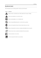
combustion (fire). Indicates an item prohibiting disassembly to avoid electric shocks or problems. Indicates an item requiring disconnection of the power plug from the electric in question. REF. Provides a description of a service mode. Provides a description of the nature of an error indication. - Canon MF3110 | Service Manual - Page 5
sors to the input of the DC controller PCB and from the output of the DC controller PCB to the loads. The descriptions in this Service Manual are subject to change without notice for product improvement or other pur poses, and major changes will be communicated in the form of - Canon MF3110 | Service Manual - Page 6
- Canon MF3110 | Service Manual - Page 7
Printer Driver ...1 4 1.3 Names of Parts...1 5 1.3.1External View...1 5 1.3.2Operation panel ...1 7 1.4 Safety...1 8 1.4.1Safety of Laser Light ...1 8 1.4.2Handling the Laser Unit ...1 8 1.4.3Safety of Toner Configuration ...2 9 2.5.2 Protective Function ...2 10 2.6 External and Controls ...2 12 - Canon MF3110 | Service Manual - Page 8
...4 2 4.3 Periodical Service ...4 3 4.3.1Items Requiring Scheduled Servicing ...4 3 4.4 Cleaning...4 4 4.4.1Items Requiring Cleaning ...4 4 4.4.2Cleaning Method (external covers) ...4 5 4.4.3Cleaning Method (scanning unit) ...4 5 4.4.4Cleaning Method (printer unit) ...4 6 4.5 Lubrications - Canon MF3110 | Service Manual - Page 9
19CCD Shaft ...4 19 4.5.20Wheel Shaft ...4 19 Chapter 5ޓTROUBLE SHOOTING 5.1 Phenomenon Table ...5 1 5.1.1Symptoms ...5 1 Service Tools ...5 5 5.4.1Special Tools ...5 5 5.5 Error Code ...5 6 5.5.1 Outline...5 6 5.5.2 Service Error Code...5 6 5.6 Service Mode...5 8 5.6.1 Outline...5 8 5.6.2 Service - Canon MF3110 | Service Manual - Page 10
- Canon MF3110 | Service Manual - Page 11
Chapter 1ޓPRODUCT DESCRIPTION - Canon MF3110 | Service Manual - Page 12
- Canon MF3110 | Service Manual - Page 13
1Printing Speed ...1 3 1.2.2Stack Upon Delivery ...1 3 1.2.3System Requirements for Printer Driver ...1 4 1.3 Names of Parts...1 5 1.3.1External View...1 5 1.3.2Operation panel ...1 7 1.4 Safety...1 8 1.4.1Safety of Laser Light ...1 8 1.4.2Handling the Laser Unit ...1 8 1.4.3Safety of Toner ...1 9 - Canon MF3110 | Service Manual - Page 14
- Canon MF3110 | Service Manual - Page 15
Exposure Method Semi conductor laser Development Method Toner projection Transfer Method Roller transfer Fixing method On demand fixing Delivery method Facedown /Faceup Toner level detection function None Toner supply type Toner cartridge replacement / Cartridge EP 27 Document type - Canon MF3110 | Service Manual - Page 16
paper (64 to 90 g/m2), Heavy paper (91 to 128 g/m2), Transparency Plain paper (64 to , Envelope (DL, ISO C5, COM10, MONARCH) Plain paper (64, 75, 80 g/m2): approx. 250 sheets, Heavy paper ( approx. 20 sheets 1 sheet 99 sheets Yes 15 to 32.5 deg C 20 to 80 %RH 200 240V, 50 60Hz approx. 700 W 449 - Canon MF3110 | Service Manual - Page 17
Plain paper L Heavy paper A4 ( to 64 g/m2) 20 20 20 A4 (65 to 90 g/m2) 18 10 B5 (64 to 90 g/m2) 8 8 4 A5 (64 to 90 g/m2) 8 8 4 A4 unit: sheets/min) 1.2.2 Stack Upon Delivery 0007-6394 Paper type Plain paper (64 to 75 g/m2) Heavy paper (91 to 128 g/m2) Transparency Label Envelope - Canon MF3110 | Service Manual - Page 18
environment with the access to CD ROM PC equipped with a USB port and the USB class driver installed T-1-3 OS Windows 98 Windows Me Windows 2000* Professional Windows XP* CPU RAM Intel Pentium 90 MHz or greater 32 MB of RAM, 64 MB or greater is recommended Intel Pentium 150 MHz or greater - Canon MF3110 | Service Manual - Page 19
1.3 Names of Parts 1.3.1 External View F-1-1 [1] Platen glass cover [2] Platen glass [3] Operation panel [4] Output tray [1] [2] [3] [4] [5] [6] [7] T-1-4 [5] Front cover [6] Multi purpose feeder [7] Cassette Chapter 1 0007-6429 1-5 - Canon MF3110 | Service Manual - Page 20
Chapter 1ޓRunning H/F 5 [1] F-1-2 [2] [3] [4] T-1-5 [1] USB port [2] Face up cover [3] Power socket [4] Extension cover 1-6 - Canon MF3110 | Service Manual - Page 21
15][16] [17] [1] COPY key [2] SCAN key [3] Enlarge/Reduce key [4] Exposure key [5] Alarm indicator [6] LCD [7] Numeric keys [8] Start key [9] Stop/Reset key T-1-6 [10] Energy Saver key [11] Collate/2on1 key [12] Image Quality key [13] Memory indicator [14] Menu key [15] Cursor keys [16] OK key [17 - Canon MF3110 | Service Manual - Page 22
by the user. 1.4.2 Handling the Laser Unit 0007-8181 The laser scanner unit emits invisible laser light inside it. If exposed to laser light, the human eye can irreparably be damaged. Never attempt to disassemble the laser scanner unit. (It is not designed for servicing in the field). The covers - Canon MF3110 | Service Manual - Page 23
composed of plastic, iron, and small amounts of dye. Chapter 1 0002-8619 Do not put the toner into fire. It may explode. Toner on the Skin or Clothes 1. If your skin or clothes came into contact with toner, wash with water at once. 2. Do not use warm or hot water, which will cause - Canon MF3110 | Service Manual - Page 24
- Canon MF3110 | Service Manual - Page 25
Chapter 2ޓTECHNICAL REFERENCE - Canon MF3110 | Service Manual - Page 26
- Canon MF3110 | Service Manual - Page 27
1 2.1.1 Overview/Configuration ...2 1 2.1.1.1 Overview ...2 1 2.2 Laser Exposure ...2 2 2.2.1 Overview/Configuration ...2 2 2.2.1.1 Overview ...2 9 2.5.1.1 Overview ...2 9 2.5.2 Protective Function ...2 10 2.5.2.1 Protective Mechanisms...2 10 2.5.2.2 Detecting a Fault in the Fixing Assembly 2 11 - Canon MF3110 | Service Manual - Page 28
- Canon MF3110 | Service Manual - Page 29
2.1 Document Feed and Exposure System 2.1.1 Overview/Configuration 2.1.1.1 Overview [2] [1] Chapter 2 0007-8185 F-2-1 T-2-1 [1] Flatbed motor [2] CCD unit The CCD unit driven by the flatbed motor reads out image data of a document on the platen glass. 2-1 - Canon MF3110 | Service Manual - Page 30
scanner motor, which are driven by signals coming from the engine controller. The laser driver serves to turn on the laser diode according to the laser control signal and video signals from the engine controller. The laser beam moves thorough the collimator less and the cylindrical lens to reach the - Canon MF3110 | Service Manual - Page 31
the 4 facet mirror and the reflecting mirror to reach and focus on the photosensitive drum. When the 4 facet mirror rotates at a specific speed, the laser beam scans the photosensitive drum in keeping with the mirror rotation, thus drawing static images on the photosensitive drum. Memo: BD Fault The - Canon MF3110 | Service Manual - Page 32
at the same time, directs the laser beam across the surface of the photosensitive drum. (The laser beam is modulated to according to the photosensitive drum is cleaned by the cleaning blade so that it is free of residual toner; after cleaning, the primary charging roller once again charges the - Canon MF3110 | Service Manual - Page 33
Chapter 2 Drum Cover Shutter If the surface of the photosensitive drum is exposed to strong light, it develops what is know as "photo memory," which can cause white spots or black lines in images. To protect the drum against light, the machine is equipped with a drum cover shutter. The drum cover - Canon MF3110 | Service Manual - Page 34
pressure roller) [8] Delivery roller [9] Face up cover [10] Face up delivery [11] Face down delivery roller [12] Face down delivery [13] Main motor [14] Cassette pickup solenoid [15] Manual feed pickup solenoid [16] Cassette paper sensor [17] Manual feed paper sensor [18] Top sensor [19] Delivery - Canon MF3110 | Service Manual - Page 35
is closed, on the other hand, the paper is moved along the feed guide of the cover, and is delivered face down at the top of the laser/scanner and the fixing unit become ready for operation. When the laser/scanner and the fixing unit become ready for operation, the machine turns off the manual - Canon MF3110 | Service Manual - Page 36
Chapter 2ޓRunning H/F 5 2.4.2.2 Delay Jams 2.4.2.2.1 Pickup Delay Jam 0003-0657 If the top sensor does not detect the leading edge of paper within 1.2 sec after the start of pickup operation, the machine initiates pickup operation once gain. The machine identifies a pickup delay jam if the top - Canon MF3110 | Service Manual - Page 37
the pressure roller: the fixing film has a built in fixing heater, thermistor, and thermal fuse. The toner transferred to paper is heated by the fixing heater, which provides heat through the fixing film; the toner is forced under the pressure roller so that it is fused into the fibers of the paper - Canon MF3110 | Service Manual - Page 38
exceeds a specific level, the machine cuts off the power to the fixing heater regardless of the instructions from the CPU. When the temperature of the fixing heater increases abnormally and the voltage of the fixing the thermal fuse starts to melt to cut off the power to the fixing heater. 2-10 - Canon MF3110 | Service Manual - Page 39
paper being picked up or moved at the time, and immediately turns off the main motor, scanner motor, and high voltage system and puts the printer unit in an error state. a) the reading of the main thermistor does not exceed 50 deg C within 2.34 sec after the start up temperature control - Canon MF3110 | Service Manual - Page 40
, and the system function will enter the Sleep mode. But the printer section will not enter the Sleep mode. Recovery from the Energy Saver print, scanning operation Out of paper, jam, out of toner, open the front cover, or a service error Energy Saver in the User Menu is turned off Energy - Canon MF3110 | Service Manual - Page 41
Chapter 3ޓDISASSEMBLY AND ASSEMBLY - Canon MF3110 | Service Manual - Page 42
- Canon MF3110 | Service Manual - Page 43
Unit...3 9 3.1.7.6 Removing the Board Unit...3 9 3.1.7.7 Removing the SCNT Board...3 10 3.1.8 ECNT Board ...3 10 3.1.8.1 Removing the Cassette ...3 10 3.1.8.2 Removing the left cover ...3 10 3.1.8.3 Removing the ECNT Board ...3 10 3.1.9 Power Supply PCB ...3 11 3.1.9.1 Removing the Cassette ...3 11 - Canon MF3110 | Service Manual - Page 44
the Scanner Unit...3 17 3.1.11.7 Removing the Top Cover...3 18 3.1.11.8 Removing the Right Frame...3 18 3.1.11.9 Removing the Plate...3 18 3.1.11.10 Removing the Left Frame ...3 18 3.1.11.11 Removing the Power Supply Shield Plate 3 19 3.1.11.12 Removing the Power Supply Assembly 3 19 3.1.11 - Canon MF3110 | Service Manual - Page 45
29 3.2.3.9 Removing the Flatbed Motor Unit ...3 29 3.2.3.10 Removing the CCD Unit ...3 30 3.2.4 Flatbed Motor 32 3.2.4.7 Removing the Operation Panel Unit 3 32 3.2.4.8 Removing the Scanner Cover Unit...3 32 3.2.4.9 Removing the Flatbed Motor Unit ...3 33 3.3 LASER EXPOSURE SYSTEM ...3 34 3.3.1 Laser - Canon MF3110 | Service Manual - Page 46
Removing the Right Frame...3 44 3.5.2.9 Removing the Plate...3 45 3.5.2.10 Removing the Left Frame ...3 45 3.5.2.11 Removing the Power Supply Shield the Manual Stay...3 51 3.5.4.16 Removing the Paper Feed Guide ...3 51 3.5.4.17 Removing the Paper Feed Roller ...3 52 3.5.5 Manual Pickup Solenoid - Canon MF3110 | Service Manual - Page 47
10 Removing the Left Frame...3 54 3.5.5.11 Removing the Power Supply Shield Plate 3 55 3.5.5.12 Removing the Power Supply Assembly 3 55 3.5.5.13 Removing the Manual 10 Removing the Left Frame...3 63 3.6.1.11 Removing the Power Supply Shield Plate 3 64 3.6.1.12 Removing the Fixing Film Unit ...3 64 - Canon MF3110 | Service Manual - Page 48
Contents 3.6.2.11 Removing the Power Supply Shield Plate 3 68 3.6.2.12 Removing the Fixing Film Unit...3 68 3.6.2.13 Removing the Fixing Pressure Roller 3 69 - Canon MF3110 | Service Manual - Page 49
3.1 EXTERNAL AND CONTROLS SYSTEM 3.1.1 Front Cover 3.1.1.1 Removing the Cassette 0002-6889 1) Remove the cassette by holding the cassette handle. 3.1.1.2 Removing the front cover 0007-7439 1) Open the front cover [1] and remove the arm claws [2] to disengage the connection. 2) Remove the - Canon MF3110 | Service Manual - Page 50
Chapter 3ޓ 3.1.2.3 Removing the left cover 0007-7446 1) Open the front cover [1], and remove the 2 screws [2] on the front side. 3.1.2.4 Removing the rear cover 0007-7449 1) Opening the face up cover [1], and then lower the fixing pressure release levers [2] on both sides and release the - Canon MF3110 | Service Manual - Page 51
board, and remove the screw [3]. (Remove the flat cable from the core.) 2) Remove the 2 screws [4] and the 2 pins [5] on the right and left sides. [1] [3] [4] [5] [2] [1] F-3-12 F-3-10 3.1.3.4 Removing the rear cover 0007-7450 1) Opening the face up cover [1], and then lower the 3-3 - Canon MF3110 | Service Manual - Page 52
Chapter 3ޓ 3) Remove the 2 screws on the back [1]. Slide the scanner unit [2] to the back; then, remove it by lifting it. [2] [1] 3.1.4.2 Removing the right cover 0007-7418 1) Open the front cover [1], and remove the 2 screws [2] on the front side. F-3-13 3.1.3.6 Removing the Top Cover - Canon MF3110 | Service Manual - Page 53
3.1.5.2 Removing the left cover 0007-7419 1) Open the front cover [1], and remove the 2 screws [2] on the front side. Chapter 3 3.1.6 Operation Panel Unit 3.1.6.1 Removing the Cassette 0007-9904 3.1.6.2 Removing the right cover 0007-7486 1) Open the front cover [1], and remove the 2 screws [2] - Canon MF3110 | Service Manual - Page 54
Chapter 3ޓ 3.1.6.3 Removing the left cover 0007-7487 1) Open the front cover [1], and remove the 2 screws [2] on the front side. [2] [1] F-3-21 2) Remove the 2 screws [1] on the back side, and remove the left cover [2]. [2] [1] F-3-22 3.1.6.4 Removing the rear cover 0007-7488 1) Opening the - Canon MF3110 | Service Manual - Page 55
3) Remove the 2 screws on the back [1]. Slide the scanner unit [2] to the back; then, remove it by lifting it. [2] [1] Chapter 3 3.1.6.7 Removing Operation Panel Unit the 0007-7491 1) Reomve the 2 screws [1], and remove the flat cable from the core. [1] F-3-25 3.1.6.6 Removing the Board - Canon MF3110 | Service Manual - Page 56
you pull it toward you. [2] F-3-31 3.1.7.3 Removing the left cover 0007-7477 1) Open the front cover [1], and remove the 2 screws [2] on the front side. [3] [1] F-3-34 [3] [4] [2] [1] F-3-32 3-8 - Canon MF3110 | Service Manual - Page 57
3.1.7.5 Removing the Scanner Unit 0007-7479 1) Remove the connector [1] and the flat cable [2] on the ECNT board, and remove the screw [3]. (Remove the flat cable from the core.) 2) Remove the 2 screws [4] and the 2 pins [5] on the right and left sides. Chapter 3 3.1.7.6 Removing the Board - Canon MF3110 | Service Manual - Page 58
5 spots [1] as well as the flat cable at 3 spots [2]. 2) Remove the 3 screws [3] and, while carefully watching the sensor flag, removes the ECNT board [4]. [3] [2] F-3-42 [2] [3] [4] [1] [3] [2] [1] F-3-40 3-10 - Canon MF3110 | Service Manual - Page 59
3.1.9 Power Supply PCB 3.1.9.1 Removing the Cassette 0002-7493 1) Remove the cassette by holding the cassette handle. 3.1.9.2 Removing the right cover 0007-7564 1) Open the front cover [1], and remove the 2 screws [2] on the front side. Chapter 3 3.1.9.3 Removing the left cover 0007-7568 1) - Canon MF3110 | Service Manual - Page 60
connector [1] and remove the cable from the cable guide. [1] [1] [1] F-3-49 3.1.9.6 Removing the Power Supply Assembly 0007-7697 1) Remove the 3 screws [1]. (The external cover is omitted from the illustration below to show the instructions clearly.) 2) Remove the four connectors [2] as well - Canon MF3110 | Service Manual - Page 61
on both sides [1], lower the front part of the power supply assembly [2]. Then pull it to remove the power supply assembly. [2] Chapter 3 3.1.10.2 Removing the right cover 0007-7702 1) Open the front cover [1], and remove the 2 screws [2] on the front side. [1] F-3-51 3.1.9.7 Removing the - Canon MF3110 | Service Manual - Page 62
[1], and remove the 2 screws [2] on the front side. 3.1.10.4 Removing the rear cover 0007-7704 1) Opening the face up cover remove the left cover [2]. [2] [1] F-3-56 [3] [3] [1] [4] F-3-57 3.1.10.5 Removing the Power Supply Shield Plate 0007-7706 1) Remove the connector [1] and remove - Canon MF3110 | Service Manual - Page 63
the 3 screws [1]. (The external cover is omitted from the illustration below to show the instructions clearly.) 2) Remove the four connectors [2] as well as the flat cable [3] on the ECNT board. [1] F-3-61 3.1.10.7 Removing the High Voltage Power Supply Board 0007-7709 1) Remove the flat cable - Canon MF3110 | Service Manual - Page 64
2) Remove the 2 screws [1] on the back side, and remove the right cover [2]. [2] [1] F-3-65 2) Remove the 2 screws [1] on the back side, and remove the left cover [2]. [2] [1] F-3-64 [1] F-3-66 3-16 - Canon MF3110 | Service Manual - Page 65
3.1.11.4 Removing the front cover 0007-7536 1) Open the front cover [1] and remove the arm claws [2] to disengage the connection. 2) Remove the shafts on both sides [3] while warping the shaft arms inside, and remove the front cover. Chapter 3 3.1.11.6 Removing the Scanner Unit 0007-7538 1) - Canon MF3110 | Service Manual - Page 66
Frame 0007-7542 1) Remove the 3 screws [1], and remove the right frame [2]. [2] F-3-73 3.1.11.10 Removing the Left Frame 0007-7545 1) Remove the cable [1] from the cable guide. 2) Remove the 2 screws [2], and remove the left frame [3]. F-3-72 [1] [2] [1] [2] [1] F-3-74 [3] [2] 3-18 - Canon MF3110 | Service Manual - Page 67
(so that the interior of the main unit is easily visible). 2) Remove the connector [1] on the ECNT board and take the cable off the cable guide. 3) Remove the screw [2] and remove the top sensor [3]. [2] [1] [2] F-3-76 [3] [2] [1] F-3-78 [3] [1] 3-19 - Canon MF3110 | Service Manual - Page 68
Chapter 3ޓ 3.1.12 Paper Delivery Sensor 3.1.12.1 Removing the Cassette 0002-7634 1) Remove the cassette by holding the cassette handle. 3.1.12.2 Removing the right cover 0007-7553 1) Open the front cover [1], and remove the 2 screws [2] on the front side. 3.1.12.3 Removing the left cover - Canon MF3110 | Service Manual - Page 69
3.1.12.4 Removing the front cover 0007-7556 1) Open the front cover [1] and remove the arm claws [2] to disengage the connection. 2) Remove the shafts on both sides [3] while warping the shaft arms inside, and remove the front cover. Chapter 3 3.1.12.6 Removing the Power Supply Shield Plate - Canon MF3110 | Service Manual - Page 70
3.1.12.9 Removing the Paper Delivery Sensor 0007-7563 1) Remove the connector [1] on the ECNT board and take the cable off the cable guide. (The external cover is omitted from the illustration.) 2) Remove the screw [2] and remove the paper delivery sensor [3]. [3] F-3-87 3.1.12.8 Removing the - Canon MF3110 | Service Manual - Page 71
3.2 Document Feed/ Exposure System 3.2.1 Scanner Unit 3.2.1.1 Removing the Cassette 0002-7555 1) Remove the cassette by holding the cassette handle. 3.2.1.2 Removing the right cover 0007-7453 1) Open the front cover [1], and remove the 2 screws [2] on the front side. Chapter 3 3.2.1.3 - Canon MF3110 | Service Manual - Page 72
Chapter 3ޓ 3.2.1.4 Removing the rear cover 0007-7455 1) Opening the face up cover [1], and then lower the fixing pressure release levers [2] on both sides and release the pressure. 2) Remove 2 screws [3]. 3) Remove the rear cover [4] as you pull it toward you. 3) Remove the 2 screws on the - Canon MF3110 | Service Manual - Page 73
2) Remove the 2 screws [1] on the back side, and remove the right cover [2]. [2] [1] F-3-98 3.2.2.3 Removing the left cover 0007-7495 1) Open the front cover [1], and remove the 2 screws [2] on the front side. Chapter 3 3.2.2.4 Removing the rear cover 0007-7496 1) Opening the face up cover [1], - Canon MF3110 | Service Manual - Page 74
Chapter 3ޓ 3) Remove the 2 screws on the back [1]. Slide the scanner unit [2] to the back; then, remove it by lifting it. [2] [1] 3.2.2.7 Removing Operation Panel Unit the 0007-7499 1) Reomve the 2 screws [1], and remove the flat cable from the core. [1] F-3-103 3.2.2.6 Removing the Board - Canon MF3110 | Service Manual - Page 75
3.2.2.8 Removing the Scanner Cover Unit 0007-7500 1) Remove the platen glass cover. 2) Remove the 3 screws [1]. 3) Remove the 4 front claws [2] and the 6 claws [3] on the right and left sides, and remove the scanner cover unit. [4] [3] [1] [3] [2] F-3-108 3.2.3 CCD Unit 3.2.3.1 Removing the - Canon MF3110 | Service Manual - Page 76
Chapter 3ޓ 3.2.3.4 Removing the rear cover 0007-7518 1) Opening the face up cover [1], and then lower the fixing pressure release levers [2] on both sides and release the pressure. 2) Remove 2 screws [3]. 3) Remove the rear cover [4] as you pull it toward you. 3) Remove the 2 screws on the - Canon MF3110 | Service Manual - Page 77
3.2.3.7 Removing Operation Panel Unit the 0007-7521 1) Reomve the 2 screws [1], and remove the flat cable from the core. [1] Chapter 3 3.2.3.8 Removing the Scanner Cover Unit 0007-7522 1) Remove the platen glass cover. 2) Remove the 3 screws [1]. 3) Remove the 4 front claws [2] and the 6 - Canon MF3110 | Service Manual - Page 78
Chapter 3ޓ 3.2.3.10 Removing the CCD Unit 0007-7524 1) Slide the core [2] while releasing the stopper [1]. 2) Remove the flat cable [3]. 3) Lift the right side of the shaft [4] to - Canon MF3110 | Service Manual - Page 79
3.2.4.3 Removing the left cover 0007-7503 1) Open the front cover [1], and remove the 2 screws [2] on the front side. [2] [1] F-3-125 2) Remove the 2 screws [1] on the back side, and remove the left cover [2]. [2] [1] F-3-126 3.2.4.4 Removing the rear cover 0007-7505 1) Opening the face up - Canon MF3110 | Service Manual - Page 80
the scanner cover unit. [3] F-3-131 3.2.4.7 Removing Operation Panel Unit the 0007-7509 1) Reomve the 2 screws [1], and remove the flat cable from the core. [1] [4] [3] [2] F-3-134 [1] [3] F-3-132 3-32 - Canon MF3110 | Service Manual - Page 81
3.2.4.9 Removing the Flatbed Motor Unit 0007-7512 1) Remove the 2 screws [1]. 2) While watching the CCD unit drive belt [2] carefully, remove the flatbed motor unit [3]. [2] [3] [1] F-3-135 Chapter 3 3-33 - Canon MF3110 | Service Manual - Page 82
Chapter 3ޓ 3.3 LASER EXPOSURE SYSTEM 3.3.1 Laser/Scanner Unit 3.3.1.1 Removing the Cassette 0002-7542 1) Remove the cassette by holding the cassette handle. 3.3.1.2 Removing the right cover 0007-7768 1) Open the front cover [1], - Canon MF3110 | Service Manual - Page 83
3.3.1.4 Removing the rear cover 0007-7770 1) Opening the face up cover [1], and then lower the fixing pressure release levers [2] on both sides and release the pressure. 2) Remove 2 screws [3]. 3) Remove the rear cover [4] as you pull it toward you. Chapter 3 3) Remove the 2 screws on the back - Canon MF3110 | Service Manual - Page 84
(The external cover is omitted from the illustration below to show the instructions clearly.) 2) Take the flat cable [2] off the board of the laser/ scanner unit. 3) Remove the 4 screws [3] to remove the laser/ scanner unit [4]. Ensure that the grounding plate [5] does not get lost. [5] [4] F-3-144 - Canon MF3110 | Service Manual - Page 85
3.4 IMAGE FORMATION SYSTEM 3.4.1 Transfer Charging Roller 3.4.1.1 Removing the Transfer Charging Roller 0007-7699 1) Open the front cover. 2) Hold the 2 claws [1] on the right side of the roller, lifting them up. 3) Slide the transfer charging roller [2] by sliding it to the right. [2] [1] - Canon MF3110 | Service Manual - Page 86
Chapter 3ޓ 3.5 PICKUP AND FEEDING SYSTEM 3.5.1 Cassette Pickup Roller 3.5.1.1 Removing the Cassette 0002-7053 1) Remove the cassette by holding the cassette handle. 3.5.1.2 Removing the right cover 0007-7800 1) Open the front cover [1], and remove the 2 screws [2] on the front side. 3.5.1.3 - Canon MF3110 | Service Manual - Page 87
3.5.1.4 Removing the front cover 0007-7802 1) Open the front cover [1] and remove the arm claws [2] to disengage the connection. 2) Remove the shafts on both sides [3] while warping the shaft arms inside, and remove the front cover. Chapter 3 3.5.1.6 Removing the Scanner Unit 0007-7805 1) - Canon MF3110 | Service Manual - Page 88
0007-7808 1) Remove the 3 screws [1], and remove the right frame [2]. [3] [1] [2] F-3-156 3.5.1.10 Removing the Left Frame 0007-7811 1) Remove the cable [1] from the cable guide. 2) Remove the 2 screws [2], and remove the left frame [3]. [2] [1] F-3-155 [2] [1] 3.5.1.9 Removing the - Canon MF3110 | Service Manual - Page 89
ECNT board. [1] F-3-160 3.5.1.13 Removing the Gear Unit 0007-7818 1) Remove the 2 screws [1], and detach the drive plate (small) [2]. [2] [1] [2] F-3-159 [3] [2] [1] [1] F-3-161 2) Remove the 2 gears [1]. 3) While freeing the claw, detach the gear unit [2]. [2] [1] F-3-162 3-41 - Canon MF3110 | Service Manual - Page 90
0007-7819 1) Remove the 2 screws [1], and detach the gear support [2]. 3.5.1.15 Removing the Cassette Pickup Roller 0007-7820 1) Place the [2] to remove it. [2] [1] F-3-163 2) Remove the spring [1]. 3) While freeing the claw, detach the tooth missing gear [2]. [2] [1] F-3-164 [1] [2] F-3-165 - Canon MF3110 | Service Manual - Page 91
2) Remove the 2 screws [1] on the back side, and remove the right cover [2]. [2] [1] Chapter 3 3.5.2.4 Removing the front cover 0007-7825 1) Open the front cover [1] and remove the arm claws [2] to disengage the connection. 2) Remove the shafts on both sides [3] while warping the shaft arms - Canon MF3110 | Service Manual - Page 92
Chapter 3ޓ 3.5.2.6 Removing the Scanner Unit 0007-7827 1) Remove the connector [1] and the flat cable [2] on the ECNT board, and remove the screw [3]. (Remove the flat cable from the core.) 2) Remove the 2 screws [4] and the 2 pins [5] on the right and left sides. [1] [3] [4] 3.5.2.7 - Canon MF3110 | Service Manual - Page 93
-9963 1) Remove the 5 screws [1] to remove the power supply shield plate [2]. [3] [1] [2] [2] F-3-176 3.5.2.10 Removing the Left Frame 0007-7831 1) Remove the cable [1] from the cable guide. 2) Remove the 2 screws [2], and remove the left frame [3]. [1] [1] F-3-178 3.5.2.12 Removing the - Canon MF3110 | Service Manual - Page 94
interior of the main unit is easily visible). 2) Remove the connector [1] on the ECNT board and take out the cable from the cable guide. 3) Remove the screw [2] to remove the cassette pickup solenoid [3], which is located behind the main motor. [3] [2] [1] F-3-182 2) Remove the 2 claws [1] on both - Canon MF3110 | Service Manual - Page 95
4) Remove the 2 claws [1] and remove the cassette separation pad [2] by sliding it up. [1] [2] Chapter 3 3.5.4.3 Removing the left cover 0007-7836 1) Open the front cover [1], and remove the 2 screws [2] on the front side. F-3-184 3.5.4 Paper Feed Roller 3.5.4.1 Removing the Cassette 0002-7105 1) - Canon MF3110 | Service Manual - Page 96
Chapter 3ޓ 3.5.4.4 Removing the front cover 0007-7838 1) Open the front cover [1] and remove the arm claws [2] to disengage the connection. 2) Remove the shafts on both sides [3] while warping the shaft arms inside, and remove the front cover. [3] 3.5.4.6 Removing the Scanner Unit 0007- - Canon MF3110 | Service Manual - Page 97
-7847 1) Remove the 3 screws [1], and remove the right frame [2]. [3] [1] Chapter 3 [2] F-3-195 3.5.4.10 Removing the Left Frame 0007-7849 1) Remove the cable [1] from the cable guide. 2) Remove the 2 screws [2], and remove the left frame [3]. [2] [1] F-3-194 [2] [1] 3.5.4.9 Removing - Canon MF3110 | Service Manual - Page 98
power supply assembly. [1] F-3-199 3.5.4.13 Removing the Gear Unit 0007-7853 1) Remove the 2 screws [1], and detach the drive plate (small) [2]. [2] [1] F-3-200 2) Remove the 2 gears [1]. 3) While freeing the claw, detach the gear unit [2]. [2] [1] F-3-201 3-50 - Canon MF3110 | Service Manual - Page 99
-7854 1) Remove the 2 screws [1], and detach the gear support [2]. Chapter 3 2) Remove the 3 screws [3]. While watching the sensor flag carefully, remove the manual stay [4]. [1] [2] [1] F-3-202 2) Remove the spring [1]. 3) While freeing the claw, detach the tooth missing gear [2]. [3] F-3-204 - Canon MF3110 | Service Manual - Page 100
feed roller [1], and slide it to detach. 2) Remove the 2 screws [1] on the back side, and remove the right cover [2]. [2] [1] [1] F-3-206 3.5.5 Manual Pickup Solenoid 3.5.5.1 Removing the Cassette 0002-7106 1) Remove the cassette by holding the cassette handle. 3.5.5.2 Removing the right cover - Canon MF3110 | Service Manual - Page 101
3.5.5.4 Removing the front cover 0007-7861 1) Open the front cover [1] and remove the arm claws [2] to disengage the connection. 2) Remove the shafts on both sides [3] while warping the shaft arms inside, and remove the front cover. [3] [3] [1] [2] F-3-211 3.5.5.5 Removing the rear cover 0007- - Canon MF3110 | Service Manual - Page 102
Frame 0007-7866 1) Remove the 3 screws [1], and remove the right frame [2]. [2] F-3-217 3.5.5.10 Removing the Left Frame 0007-7868 1) Remove the cable [1] from the cable guide. 2) Remove the 2 screws [2], and remove the left frame [3]. F-3-216 [1] [2] [1] [2] [3] [1] [2] F-3-218 3-54 - Canon MF3110 | Service Manual - Page 103
as the flat cable [3] on the ECNT board. [1] F-3-221 3.5.5.13 Removing the Manual Pickup Solenoid 0007-7871 1) Place the main unit down on its front face ( the cable [1] from the cable guide. 3) Remove the screw [2] to remove the manual pickup solenoid [3]. [1] [1] [2] F-3-220 [3] [2] [1] [3] - Canon MF3110 | Service Manual - Page 104
Chapter 3ޓ 3.5.6 Main Motor 3.5.6.1 Removing the Cassette 0002-7570 1) Remove the cassette by holding the cassette handle. 3.5.6.2 Removing the right cover 0007-7780 1) Open the front cover [1], and remove the 2 screws [2] on the front side. [2] [1] F-3-223 2) Remove the 2 screws [1] on the - Canon MF3110 | Service Manual - Page 105
3.5.6.4 Removing the front cover 0007-7782 1) Open the front cover [1] and remove the arm claws [2] to disengage the connection. 2) Remove the shafts on both sides [3] while warping the shaft arms inside, and remove the front cover. Chapter 3 3.5.6.6 Removing the Scanner Unit 0007-7784 1) - Canon MF3110 | Service Manual - Page 106
Frame 0007-7786 1) Remove the 3 screws [1], and remove the right frame [2]. [2] F-3-233 3.5.6.10 Removing the Left Frame 0007-7789 1) Remove the cable [1] from the cable guide. 2) Remove the 2 screws [2], and remove the left frame [3]. F-3-232 [1] [2] [1] [2] [3] [1] [2] F-3-234 3-58 - Canon MF3110 | Service Manual - Page 107
3.5.6.11 Removing the Power Supply Shield Plate 0007-7792 1) Remove the 5 screws [1] to remove the power supply shield plate [2]. [2] Chapter 3 3) As you remove the bosses on both sides [1], lower the front part of the power supply assembly [2]. Then pull it to remove the power supply assembly. - Canon MF3110 | Service Manual - Page 108
the Gear Unit 0007-7778 1) Remove the 2 screws [1], and detach the drive plate (small) [2]. [2] [1] F-3-241 2) Remove the 2 gears [1]. 3) While freeing the claw, detach the gear unit [2]. [1] F-3-239 2) Remove the 2 screws [1] on the back side, and remove the right cover [2]. [2] [2] [1] F-3-242 - Canon MF3110 | Service Manual - Page 109
3.6 FIXING SYSTEM 3.6.1 Fixing Film Unit 3.6.1.1 Removing the Cassette 0002-7190 1) Remove the cassette by holding the cassette handle. 3.6.1.2 Removing the right cover 0007-7729 1) Open the front cover [1], and remove the 2 screws [2] on the front side. Chapter 3 3.6.1.3 Removing the left - Canon MF3110 | Service Manual - Page 110
Chapter 3ޓ 3.6.1.4 Removing the front cover 0007-7732 1) Open the front cover [1] and remove the arm claws [2] to disengage the connection. 2) Remove the shafts on both sides [3] while warping the shaft arms inside, and remove the front cover. 3.6.1.6 Removing the Scanner Unit 0007-7734 1) - Canon MF3110 | Service Manual - Page 111
Frame 0007-7737 1) Remove the 3 screws [1], and remove the right frame [2]. [2] F-3-253 3.6.1.10 Removing the Left Frame 0007-7744 1) Remove the cable [1] from the cable guide. 2) Remove the 2 screws [2], and remove the left frame [3]. F-3-252 [1] [2] [1] [2] [3] [1] [2] F-3-254 3-63 - Canon MF3110 | Service Manual - Page 112
to remove the power supply shield plate [2]. 2) Remove the 2 screws [1]. Remove the Fixing entrance guide [2] by sliding it sideways back and forth. [1] [2] [1] [1] F-3-255 3.6.1.12 Removing the . 5) Remove the pressure plates [3] on both sides. [3] [1] [2] [1] [2] F-3-258 [2] F-3-256 3-64 - Canon MF3110 | Service Manual - Page 113
6) While holding the left and right frames [2] of the Fixing film unit [1], lift it up at an angle and remove it. [2] Chapter 3 2) Remove the 2 screws [1] on the back side, and remove the right cover [2]. [2] [1] [1] F-3-259 3.6.2 Fixing Pressure Roller 3.6.2.1 Removing the Cassette 0002-7191 1) - Canon MF3110 | Service Manual - Page 114
Chapter 3ޓ 3.6.2.4 Removing the front cover 0007-7757 1) Open the front cover [1] and remove the arm claws [2] to disengage the connection. 2) Remove the shafts on both sides [3] while warping the shaft arms inside, and remove the front cover. 3.6.2.6 Removing the Scanner Unit 0007-7760 1) - Canon MF3110 | Service Manual - Page 115
Frame 0007-7762 1) Remove the 3 screws [1], and remove the right frame [2]. [2] F-3-270 3.6.2.10 Removing the Left Frame 0007-7764 1) Remove the cable [1] from the cable guide. 2) Remove the 2 screws [2], and remove the left frame [3]. F-3-269 [1] [2] [1] [2] [3] [1] [2] F-3-271 3-67 - Canon MF3110 | Service Manual - Page 116
0007-7765 1) Remove the 5 screws [1] to remove the power supply shield plate [2]. [2] 2) Remove the 2 screws [1]. Remove the Fixing entrance guide [2] by sliding it sideways back and forth. [1] [1] [1] F-3-272 3.6.2.12 Removing the Fixing Film Unit 0007-7766 1) Remove the 2 screws [1] and - Canon MF3110 | Service Manual - Page 117
6) While holding the left and right frames [2] of the Fixing film unit [1], lift it up at an angle and remove it. [2] Chapter 3 3) Hold the shorter shaft [2] of the Fixing pressure roller [1] and lift it up at an angle to remove it from the bushing. Remove the Fixing pressure roller by sliding it. - Canon MF3110 | Service Manual - Page 118
- Canon MF3110 | Service Manual - Page 119
Chapter 4ޓMAINTENANCE AND INSPECTION - Canon MF3110 | Service Manual - Page 120
- Canon MF3110 | Service Manual - Page 121
1Consumable...4 2 4.3 Periodical Service...4 3 4.3.1Items Requiring Scheduled Servicing ...4 3 4.4 Cleaning ...4 4 4.4.1Items Requiring Cleaning...4 4 4.4.2Cleaning Method (external covers) ...4 5 4.4.3Cleaning Method (scanning unit) ...4 5 4.4.4Cleaning Method (printer unit) ...4 6 4.5 Lubrications - Canon MF3110 | Service Manual - Page 122
- Canon MF3110 | Service Manual - Page 123
4.1 Periodically Replaced Parts 4.1.1 Parts Requiring Periodical Replacement The machine does not have parts that require periodical replacement. Chapter 4 0003-0867 4-1 - Canon MF3110 | Service Manual - Page 124
Chapter 4ޓRunning H/F 5 4.2 Consumables 4.2.1 Consumable Work by User Item Cartridge EP 27 Service Techician None 0007-6479 T-4-1 Interval (guide) When toner in the toner cartridge being used has run out. 4-2 - Canon MF3110 | Service Manual - Page 125
4.3 Periodical Service 4.3.1 Items Requiring Scheduled Servicing The machine does not have items that require scheduled servicing. Chapter 4 0003-0865 4-3 - Canon MF3110 | Service Manual - Page 126
Service technician Cassette pickup roller Cassette separation pad Feed roller Transfer charging roller Static eliminator Paper feed guide Fixing entrance guide 57 mm When the back of paper shows traces at intervals of about 64 mm; when fixing faults occur; when paper jams; when paper wrinkles - Canon MF3110 | Service Manual - Page 127
Chapter 4 4.4.2 Cleaning Method (external covers) 0003-2119 Moisten a soft cloth with water or solution of mild detergent, making sure it is well wrung; then, wipe the soiling. If you have used detergent, be sure to remove its residue using a soft, moist cloth. After removing all soiling, dry - Canon MF3110 | Service Manual - Page 128
free paper to remove soling. [3] Feed Roller Use lint free paper to remove soling. [4] Transfer Charging Roller Use lint free paper to remove toner a brush. [6] Paper Feed Guide Use lint free paper to remove soiling. [7] Fixing Entrance Guide Use lint free paper moistened with isopropyl alcohol to - Canon MF3110 | Service Manual - Page 129
you have replaced a part in these areas or if you have removed the grease, be sure to apply grease. Printer unit [1] [2] [15] [3] [4] [5] [17] [6] F-4-3 [10] [9] [13] [8] [7] [12] [11] [14] [16] [1] Delivery idler gear [2] Fixing drive transmission gear [3] Large gear bushing R [4] Large gear - Canon MF3110 | Service Manual - Page 130
Running H/F 5 Scanner unit [1] [2] F-4-4 [1] CCD shaft T-4-4 [2] Wheel shaft 4.5.2 Delivery Idler Gear Area of application: [1] Grease: MOLYKOTE EM 50L Amount: 40 +/ 10 mg Location of application: 2 locations on gear support shaft in opposition spread in axial direction 0002-7926 [1] F-4-5 4-8 - Canon MF3110 | Service Manual - Page 131
Transmission Gear Area of application: [1] Grease: MOLYKOTE EM 50L Amount: 10 +/ 5 mg Location of application: 2 locations on gear butting ribs Gear Bushing R Area of application: [1] Grease: MOLYKOTE EM 50L Amount: 10 +/ 5 mg location of application: wall surface on inner circumferential side - Canon MF3110 | Service Manual - Page 132
Gear Area of application: [1] Grease: MOLYKOTE EM 50L Amount: 20 +/ 10 mg Location of application: rib against which gear is butted spread in circumferential Feed Gear Area of application: [1] Grease: MOLYKOTE EM 50L Amount: 10 +/ 5 mg Location of application: 1 location on boss engaging with - Canon MF3110 | Service Manual - Page 133
4.5.7 Internal Gear Area of application: [1] Grease: MOLYKOTE EM 50L Amount: 40 +/ 10 mg Location of application: 5 teeth or more of internal gear in opposition 2 locations in circumferential direction [1] F-4-10 Chapter 4 0002-7937 4-11 - Canon MF3110 | Service Manual - Page 134
of application: 5 teeth or more (covering entire small dia tooth area) Are of application: [2] Grease: MOLYKOTE EM 50L Amount: 10 +/ 5 mg Location of application support shaft of plate R (sliding surface against large gear deceleration gear) spread in axial direction [1] 0002-7938 [2] F-4-11 4-12 - Canon MF3110 | Service Manual - Page 135
4.5.9 Main Motor Area of application: [1] Grease: MOLYKOTE EM 50L Amount: 40 +/ 10 mg Location of application: 5 teeth or more (covering entire gear width) [1] F-4-12 Chapter 4 0002-7939 4-13 - Canon MF3110 | Service Manual - Page 136
Chapter 4ޓRunning H/F 5 4.5.10 Drive Releasing Arm Area of application: [1] Grease: MOLYKOTE EM 50L Amount: 10 +/ 5 mg Location of application: 4 locations on sliding surface against gear support shaft of drive releasing arm [1] 0002-7940 F-4-13 4-14 - Canon MF3110 | Service Manual - Page 137
surface between FU delivery roller shaft and FU delivery roller bushing Area of application: [3] Grease: MOLYKOTE EM 50L Amount: 10 +/ 5 mg Location of application: sliding surface between FU delivery roller shaft and delivery guide (FU delivery roller shaft stop rib) [1] [2] [3] F-4-14 4-15 - Canon MF3110 | Service Manual - Page 138
Chapter 4ޓRunning H/F 5 4.5.12 Pickup Idler Gear Are of application: [1] Grease: MOLYKOTE EM 50L Amount: 10 +/ 5 mg Location of application: 2 locations on pickup idler gear support shaft 5 teeth or more (covering entire large diameter tooth surface of pickup idler gear) 0002-7944 [1] F-4-15 - Canon MF3110 | Service Manual - Page 139
more (covering entire surface of fixing deceleration gear; small diameter teeth) 0002-7954 Area of application: [2] Grease: MOLYKOTE EM 50L Amount: 10 +/ 5 mg Location application: tip of feed deceleration gear butting rib in circumferential direction over a length of 1/2 or more Area of location - Canon MF3110 | Service Manual - Page 140
of application entire sliding surface against FD delivery bushing [1] [1] F-4-18 4.5.16 Large Gear Bushing F Area of application: [1] Grease: MOLYKOTE EM 50L Amount: 10 +/ 5 mg Location of application: entire sliding surface against large gear support shaft [1] F-4-19 4-18 0002-7948 0002-7950 - Canon MF3110 | Service Manual - Page 141
contact spring F) Chapter 4 0002-7953 [1] F-4-20 4.5.18 Cassette Pickup Roller 0003-6451 Area of application: [1] Grease: MOLYKOTE EM 50L Amount: approx. 10 mg Location of application: cassette pickup roller shaft, main unit frame (around the bushing), and the area where contacts the cassette - Canon MF3110 | Service Manual - Page 142
4.5.19 CCD Shaft Area of application: [1] Grease: MOLYKOTE EM 50L Amount: suitable amount Location of application: part of CCD shaft where contacts the CCD unit (all the faces in the shaft direction) 0003-2409 [1] F-4-22 4.5.20 Wheel Shaft Area of application: [1] Grease: MOLYKOTE EM 50L Amount: - Canon MF3110 | Service Manual - Page 143
Chapter 5ޓTROUBLE SHOOTING - Canon MF3110 | Service Manual - Page 144
- Canon MF3110 | Service Manual - Page 145
E000 Fixing Unit Failure...5 6 5.5.2.3 E100 Laser/Scanner Unit Failure ...5 7 5.6 Service Mode...5 8 5.6.1 Outline...5 8 5.6.1.1 Service Data Setting ...5 8 5.6.1.2 Service Data Entry Method ...5 9 5.6.1.3 Service Data Flowchart ...5 9 5.6.2 Service Soft Switch Settings (SSSW)...5 12 5.6.2.1 Outline - Canon MF3110 | Service Manual - Page 146
- Canon MF3110 | Service Manual - Page 147
There are vertical black lines or a vertical white line in a solid black image. When manual paper size is set to envelope, the LCD in standby mode shows ENV. regardless of envelope and then on with paper in its manual feed section. For details, see the instructions given as remedial action. 5-1 - Canon MF3110 | Service Manual - Page 148
heavy paper mode. 5.2.2 Malfunction 5.2.2.1 Control Panel Related 5.2.2.1.1 When manual paper size is set to envelope, the LCD in standby mode even if printing is made with other size paper. The printer engine does not support A5 size. Since image printed on a sheet is - Canon MF3110 | Service Manual - Page 149
place. 5.2.4.2 The machine identifies a jam when its power is turned off and then on with paper in its manual feed section 0007-8094 The machine is designed to identify a jam if the manual feed paper sensor is on when it is tuned on, as it is not sure whether the paper - Canon MF3110 | Service Manual - Page 150
Chapter 5ޓRunning H/F 5 5.3 Measurement and Adjustment 5.3.1 Basic Adjustments 5.3.1.1 Items of Adjustment 0003-3366 The machine does not have items that are cited for adjustment. 5-4 - Canon MF3110 | Service Manual - Page 151
5.4 Service Tools 5.4.1 Special Tools Tool Grease (MOLYKOTE EM 50L) Grease (MOLYKOTE EMD 110) Grease (IF 20) Grease (MOLYKOTE 41) T-5-2 Description Apply to specified areas. Apply to - Canon MF3110 | Service Manual - Page 152
can readily find out how to correct the fault by simply referring to the service manual. An error code may be either of the following two types: Service Error Codes If a fault calls for a service man for correction, it is indicated as a service man error code in the form of "SYSTEM ERROR E+number - Canon MF3110 | Service Manual - Page 153
/Scanner unit failure. Remedy: 1) Turn the power off and on. 2) Make sure that the Laser/Scanner unit (J801) and ECNT board (J503) are properly connected. 3) Make sure that the Laser/Scanner unit and ECNT board (J504) are properly connected. 4) Make sure connections of the boards (power supply board - Canon MF3110 | Service Manual - Page 154
use. #PRINT Do not use. #NETWORK Do not use. #CODEC Do not use. #SYSTEM Do not use. #REPORT Use it to output reports on various service data. #DOWNLOAD Do not use. #CLEAR Various data are initialized by selecting one of these setting items. 5-8 - Canon MF3110 | Service Manual - Page 155
Data Entry Method You can enter the Service Mode with the following operation. Menu # #1 SSSW F-5-1 5.6.1.3 Service Data Flowchart Service menu #SSSW (Service soft switch setting) #+No. Bit 7 6 5 4 3 2 1 0 SW01 0 Error management SW02 Not used SW03 Not used SW04 Not used SW05 Not - Canon MF3110 | Service Manual - Page 156
: 100: SW001 to SW050: Not used 001 to 100: Not used SW001 SW050 001: 350: SW001 to SW050: Not used 001 to 350: Not used F-5-3 5-10 - Canon MF3110 | Service Manual - Page 157
#PRINT #NETWORK #CODEC #SYSTEM F-5-4 SW001 SW050 001: 050: SW001 to SW050: Not used 001 to 050: Not used SW001 SW050 001: 050: SW001 to SW050: Not used 001 to 050: Not used SW001 SW050 001: 050: SW001 to SW050: Not used 001 to 050: Not used SW001 SW050 001: 100: SW001 to SW050: Not used 001 - Canon MF3110 | Service Manual - Page 158
050: Not used #DOWNLOAD (Download) #CLEAR (Data initialization mode settins) Not used TEL & USER DATA SERVICE DATA COUNTER TYPE ALL bit switches. The figure below shows which numbers are assigned to which bits. Each bit has a value of either 0 or 1. Bit 7 Bit 6 Bit 5 Bit 4 Bit 3 Bit 2 Bit 1 Bit - Canon MF3110 | Service Manual - Page 159
Below are examples showing how to read bit switch tables. Indicates that the setting is "1". Bit Function 0 Service error code 1 Not used 2 Not used 3 Not used 4 Not used 5 Not used 6 Not used 7 Not used F-5-7 5.6.2.2 SSSW SW14 1 Output - Indicates that the setting is "0". 0 Not - Canon MF3110 | Service Manual - Page 160
Chapter 5ޓRunning H/F 5 5.6.3 ROM Management (ROM) 5.6.3.1 ROM Information such as ROM (program software) version number is displayed on the display. This mode is for confirmation only, and any entry cannot be made. Menu Display TEST TEST MODE # MODE - Canon MF3110 | Service Manual - Page 161
Chapter 5 5.6.4.1.2 Test Mode Flowchart 0007-6680 To operate the test mode, after pressing the Menu key, press the # key and select "SERVICE MODE". After this, select "TEST MODE" with the cursor keys, and press the OK key. Turn OFF and back ON the power to end the - Canon MF3110 | Service Manual - Page 162
complete (no error) Error display WRT=33CC RD=33EC ADR=BF840201 WRT : data written RD : data read ADR : address Restart by pressing Start button F-5-10 (Normal end) DRAM TEST 40960KB complete (error) Before D RAM test, output all image data in image memory. When D RAM test is performed, all - Canon MF3110 | Service Manual - Page 163
Test menu is selected by pressing the numeric key 3 from the test mode menu. In this test, various print patterns are output from the printer. As service print patterns, press the numeric key 2 from the Print Test menu to select "3 2: BLACK" or press the numeric key 6 to select "3 6: ENDURANCE". Do - Canon MF3110 | Service Manual - Page 164
Chapter 5ޓRunning H/F 5 5.6.4.4 Faculty Test 5.6.4.4.1 FACULTY Tests The faculty tests are selected by pressing the numeric key 6 from the test mode menu. These tests test the following faculties of this machine. 0007-6690 Test type Sensor tests Operation panel test T-5-6 Overview Test whether - Canon MF3110 | Service Manual - Page 165
: Cartridge sensor on/of : Front cover switch on/of : Cassette recording paper sensor/Manual paper feed sensor/Top sensor /Paper delivery sensor/Not used on/of Pressing the 2 key JAM of JAM 000 TN of TN253 JAM : Paper delivery jam detection on/of TN : Toner sensor on/of and toner - Canon MF3110 | Service Manual - Page 166
Chapter 5ޓRunning H/F 5 5.6.4.4.3 Operation panel tests 0007-6702 The operation panel test is selected by pressing the numeric key 7 from the faculty test menu. In this test, check that the display, LED lamps and keys on the operation panel are operating correctly. Display test Pressing the - Canon MF3110 | Service Manual - Page 167
6-3 OPERATION PANEL Press Start Key HHHHHHHHHHHHHHHHHHHH HHHHHHHHHHHHHHHHHHHH H pattern displayed Press Start Key All LCD dots displayed Press Start Key The LED lamps other than the Energy Saver key go on Press Start Key 123456789*0#ABCDEDFG HIJ Q When a key is pressed, the corresponding - Canon MF3110 | Service Manual - Page 168
- Canon MF3110 | Service Manual - Page 169
Chapter 6ޓAPPENDIX - Canon MF3110 | Service Manual - Page 170
- Canon MF3110 | Service Manual - Page 171
%QPVGPVU Contents 6.1 Outline of Electrical Components ...6 1 6.1.1 Sensor...6 1 6.1.1.1 Arrangement of Sensors and Switches 6 1 6.1.2 PCBs ...6 2 6.1.2.1 Arrangement of PCBs...6 2 - Canon MF3110 | Service Manual - Page 172
- Canon MF3110 | Service Manual - Page 173
F-6-1 [3] [2] [1] Cassette Paper Sensor Used to detect the presence/absence of paper in the cassette. [2] Manual Feed Paper Sensor Used to detect the presence/absence of paper in the manual feed section. [3] Paper Leading Edge Sensor (top sensor) Used to detect the leading/trailing edge of paper - Canon MF3110 | Service Manual - Page 174
Used to control the whole of the system. [2] ECNT Board Used to control the operation of the printer unit. [3] High Voltage Power Supply Board Used to supply high voltage power to the printer unit. [4] Power Supply Board Used to control the supply of power to various components. 0007-8187 6-2 - Canon MF3110 | Service Manual - Page 175
Aug 27 2004 - Canon MF3110 | Service Manual - Page 176
-
 1
1 -
 2
2 -
 3
3 -
 4
4 -
 5
5 -
 6
6 -
 7
7 -
8
-
9
-
10
-
11
-
12
-
13
-
14
-
15
-
16
-
17
-
18
-
19
-
20
-
21
-
22
-
23
-
24
-
25
-
26
-
27
-
28
-
29
-
30
-
31
-
32
-
33
-
34
-
35
-
36
-
37
-
38
-
39
-
40
-
41
-
42
-
43
-
44
-
45
-
46
-
47
-
48
-
49
-
50
-
51
-
52
-
53
-
54
-
55
-
56
-
57
-
58
-
59
-
60
-
61
-
62
-
63
-
64
-
65
-
66
-
67
-
68
-
69
-
70
-
71
-
72
-
73
-
74
-
75
-
76
-
77
-
78
-
79
-
80
-
81
-
82
-
83
-
84
-
85
-
86
-
87
-
88
-
89
-
90
-
91
-
92
-
93
-
94
-
95
-
96
-
97
-
98
-
99
-
100
-
101
-
102
-
103
-
104
-
105
-
106
-
107
-
108
-
109
-
110
-
111
-
112
-
113
-
114
-
115
-
116
-
117
-
118
-
119
-
120
-
121
-
122
-
123
-
124
-
125
-
126
-
127
-
128
-
129
-
130
-
131
-
132
-
133
-
134
-
135
-
136
-
137
-
138
-
139
-
140
-
141
-
142
-
143
-
144
-
145
-
146
-
147
-
148
-
149
-
150
-
151
-
152
-
153
-
154
-
155
-
156
-
157
-
158
-
159
-
160
-
161
-
162
-
163
-
164
-
165
-
166
-
167
-
168
-
169
-
170
-
171
-
172
-
173
-
174
-
175
-
176
 |
 |

Aug 27 2004
Service Manual
MF3110 Series
LaserBase MF3110