Canon MF4690 Service Manual
Canon MF4690 - ImageCLASS B/W Laser Manual
 |
UPC - 013803076820
View all Canon MF4690 manuals
Add to My Manuals
Save this manual to your list of manuals |
Canon MF4690 manual content summary:
- Canon MF4690 | Service Manual - Page 1
Service Manual MF4600 Series imageCLASS MF4690 Jul 18 2007 - Canon MF4690 | Service Manual - Page 2
- Canon MF4690 | Service Manual - Page 3
reserved. Under the copyright laws, this manual may not be copied, reproduced or translated into another language, in whole or in part, without the written consent of Canon Inc. COPYRIGHT © 2001 CANON INC. Printed in Japan Caution Use of this manual should be strictly supervised to avoid disclosure - Canon MF4690 | Service Manual - Page 4
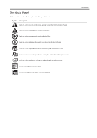
(fire). Indicates an item prohibiting disassembly to avoid electric shocks or problems. Indicates an item requiring disconnection of the power plug from the electric in question. REF. Provides a description of a service mode. Provides a description of the nature of an error indication. Introduction - Canon MF4690 | Service Manual - Page 5
sensors to the input of the DC controller PCB and from the output of the DC controller PCB to the loads. The descriptions in this Service Manual are subject to change without notice for product improvement or other purposes, and major changes will be communicated in the form of - Canon MF4690 | Service Manual - Page 6
- Canon MF4690 | Service Manual - Page 7
8 1.1.4 Function List ...1- 9 1.1.4.1 Scanning Range ...1- 9 1.1.4.2 Recording Range (Copy) ...1- 10 1.1.4.3 Recording Range (Reception) ...1- 10 1.1.4.4 Recording Range (Printer) ...1- 11 1.1.4.5 Operation Environment of the Printer Driver...1- 11 1.1.4.6 Network Specifications...1- 11 1.1.4.7 SEND - Canon MF4690 | Service Manual - Page 8
the Laser Scanner Unit ...5- 4 Chapter 6 Image Formation 6.1 Overview/Configuration ...6- 1 6.1.1 Configuration...6- 1 6.1.2 Print Process...6- 1 6.2 Driving and Controlling the High-Voltage System 6- 3 6.2.1 Generation of Transfer Charging Bias ...6- 3 6.3 Toner Cartridge ...6- 3 6.3.1 Toner Level - Canon MF4690 | Service Manual - Page 9
Jams...7- 3 7.3.3.1 Pickup Stationary Jam ...7- 3 7.3.3.2 Delivery Stationary Jam ...7- 3 7.3.4 Other Jams ...7- 3 7.3.4.1 Door Open Jam ...7- 3 7.3.4.2 Wrapping Jam ...7- 3 7.3.4.3 Residual Jam at Startup ...7- 4 7.4 Duplex Unit ...7- 5 7.4.1 Overview...7- 5 7.5 Parts 3 9.3.6 Cartridge Cover ...9- - Canon MF4690 | Service Manual - Page 10
the Motor driver PCB ...9- 7 Chapter 10 Maintenance and Inspection 10.1 Periodically Replaced Parts...10- 1 10.1.1 Periodically Replaced Parts ...10- 1 10.2 Consumables...10- 1 10.2.1 Consumable ...10- 1 10.3 Periodical Service ...10- 1 10.3.1 Periodically Service Items ...10- 1 10.4 Cleaning ...10 - Canon MF4690 | Service Manual - Page 11
Chapter 13 Error Code 13.1 Error Code ...13- 1 13.1.1 List of Error Codes...13- 1 13.2 Fax Error Codes ...13- 3 13.2.1 Outline ...13- 3 13.2.1.1 Error Code Outline ...13- 3 13.2.2 User Error Code...13- 3 13.2.2.1 User Error Code ...13- 3 13.2.3 Service Error Code ...13- 3 13.2.3.1 Service Error Code - Canon MF4690 | Service Manual - Page 12
on a document fed from ADF 14- 18 14.6.7 - Canon MF4690 | Service Manual - Page 13
.3.1 Scan Test ((2) SCAN TEST) ...14- 28 14.13.4 Print Test...14- 28 14.13.4.1 Print Test ((3) PRINT TEST) ...14- 28 14.13.5 Modem Test ...14- 28 14.13.5.1 MODEM Test ((4) MODEM TEST)...14- 28 14.13.6 Faculty Test ...14- 31 14.13.6.1 FUNCTION TEST ...14- 31 14.13.7 Cleaning Mode - Canon MF4690 | Service Manual - Page 14
Contents - Canon MF4690 | Service Manual - Page 15
Chapter 1 Introduction - Canon MF4690 | Service Manual - Page 16
- Canon MF4690 | Service Manual - Page 17
...1-8 1.1.4 Function List ...1-9 1.1.4.1 Scanning Range...1-9 1.1.4.2 Recording Range (Copy)...1-10 1.1.4.3 Recording Range (Reception) ...1-10 1.1.4.4 Recording Range (Printer) ...1-11 1.1.4.5 Operation Environment of the Printer Driver ...1-11 1.1.4.6 Network Specifications ...1-11 1.1.4.7 SEND - Canon MF4690 | Service Manual - Page 18
- Canon MF4690 | Service Manual - Page 19
-1797 [10] [11] [12] [13] [8] [7] [6] [5] [1] ADF (Automatic Document Feeder) [2] Slide Guides [3] Document feeder tray [4] Document delivery tray [5] Operation panel [6] USB memory port [7] Output tray [8] Paper cassette [9] Scanning area [17] F-1-1 [16] [15] [14] [10] Platen glass [11 - Canon MF4690 | Service Manual - Page 20
Chapter 1 Rear View (Body) [1] [6] [2] [1] USB port [2] Rear cover [3] Power socket [5] [4] [3] F-1-2 [4] Telephone line jack [5] External device jack [6] Ethernet port 1-2 - Canon MF4690 | Service Manual - Page 21
Section View (ADF) pressure roller [8] copyboard glass (scanning glass) [9] delivery roller [10] fixing film unit [11] laser scanner unit [12] primary charging roller [13] developing cylinder [14] pick-up roller separation pad cartridge duplexing feeding roller transfer charging roller - Canon MF4690 | Service Manual - Page 22
[3] [COPY] key [4] [SEND/FAX] key [5] [SCAN] key [6] [Additional Functions] key [7] [2-Sided] key [8] [Enlarge/Reduce] key [9] [Density] key [10] [Image Quality] key [11] [Collate/2 on 1] key [12] [Log In/Out] key (ID) key [13] [Energy Saver] key T-1-1 [14] [Stop/Reset] key [15] Error indicator [16 - Canon MF4690 | Service Manual - Page 23
[3] [Coded Dial] key Chapter 1 1-5 - Canon MF4690 | Service Manual - Page 24
in the figure below is attached onto the cover of the laser scanner unit. [1] F-1-8 1.1.2.4 Safety of the Toner 0016-1806 Toner in General Toner is a non-toxic material made up of plastic, iron, and small amounts of dye. Do not throw toner into fire. Doing so can lead to explosion. Contact with - Canon MF4690 | Service Manual - Page 25
method Drum cleaning method Fixing method Toner supply type Toner type Toner save mode Original type Maximum original size Reproduction ratio Reading resolution Printing resolution Warm-up time First print time Print speed Cassette paper size Multifeeder paper size Cassette paper type Multifeeder - Canon MF4690 | Service Manual - Page 26
13.4kg (including toner cartridges) 1.1.3.2 ADF Specifications Error correction Minimum receive input level Modem IC Scanning line density Half tone Printing resolution Reduction for reception FAX ID: 2 digits (default is 25) One-touch dial: 8 Speed dial: 192 Group dial: Maximum 199 - Canon MF4690 | Service Manual - Page 27
Dual access Image data backup 1.1.4 Function List 1.1.4.1 Scanning Range Number of reservations: 70 max. backup particulars: memory reception, memory transmission, broadcast image data backup IC: 128 MB (SDARAM) Backup battery: rechargeable capacity backup length: about 1 hour [1] [2] [4] [3] - Canon MF4690 | Service Manual - Page 28
width [4] right margin [5] trailing edge margin [6] F-1-10 [6] trailing edge margin [7] non-scanning area [8] scanning range [9] trailing edge of document item effective recording width effective recording left margin right margin leading edge margin trailing edge margin A4 204 +1.0/-2.0 mm - Canon MF4690 | Service Manual - Page 29
Professional, Windows XP Professional, Windows XP Home Edition, Windows Server 2003, Windows Vista, MacOS X v10.2.8 or later Hardware environment - IBM PC or IBM compatible PC - CD-ROM drive or network environment accessible to CD-ROM - PC equipped with USB port and installed with USB class driver - Canon MF4690 | Service Manual - Page 30
Server, Windows 2000 Professional, Windows XP Professional, Windows XP Home Edition, Windows Server 2003, Windows Vista, MacOS X v10.2.8 or later, Red Hat Linux 7.2 Hardware environment - Windows or IBM compatible PC Protocol - NetBIOS over TCP/IP (NetBT) Mail forwarding/receiving server software - Canon MF4690 | Service Manual - Page 31
Chapter 2 Basic Operation - Canon MF4690 | Service Manual - Page 32
- Canon MF4690 | Service Manual - Page 33
Contents Contents 2.1 Construction ...2-1 2.1.1 Function Configuration ...2-1 2.2 Basic Sequence ...2-1 2.2.1 Basic Operation Sequence ...2-1 - Canon MF4690 | Service Manual - Page 34
- Canon MF4690 | Service Manual - Page 35
0016-1809 The functions of this host machine are mainly composed of the 7 blocks: System Control System, Scanning Control System, Printer Control System, Laser Scanner System, Image Formation System, Fixing System, Pickup/Feeding System. Below is the block diagram. System Control System - Canon MF4690 | Service Manual - Page 36
- Canon MF4690 | Service Manual - Page 37
Chapter 3 Original Exposure System - Canon MF4690 | Service Manual - Page 38
- Canon MF4690 | Service Manual - Page 39
Control / Function List ...3-1 3.1.2 Major Components...3-1 3.2 Various Control...3-3 3.2.1 Dirt Sensor Control ...3-3 3.2.1.1 Outline...3-3 3.3 Parts Replacement Procedure...3-5 3.3.1 Scanner Unit...3-5 3.3.1.1 Preparation for Removing the Control Panel Assembly ...3-5 3.3.1.2 Removing the Control - Canon MF4690 | Service Manual - Page 40
- Canon MF4690 | Service Manual - Page 41
(CS) ADF: document stream reading by fixed contact sensor (CS) scanning resolution 600 dpi (horizontal scanner) X 600 dpi (vertical scanner) number of gradations 256 gradations magnification 50% to 200% horizontal: image processing by SCNT board vertical: change of carriage shift speed - Canon MF4690 | Service Manual - Page 42
Chapter 3 Book motor (M2) drive belt drive pulley drive pulley contact sensor F-3-1 3-2 - Canon MF4690 | Service Manual - Page 43
thus preventing dust from showing up in the image. This control is performed only when the ADF light from the surface of the ADF platen guide at scanning position to judge if there is dust at cleaning of glass surface. 0.5mm 0.5mm ABC Stream reading glass Lens Contact sensor F-3-3 Platen guide - Canon MF4690 | Service Manual - Page 44
Chapter 3 Position A B C T-3-2 Description Reference position for scanning Approx. 0.5mm from the reference point Approx. 1.0mm from the reference point 3-4 - Canon MF4690 | Service Manual - Page 45
3.3 Parts Replacement Procedure 3.3.1 Scanner Unit 3.3.1.1 Preparation for Removing the Control Panel Assembly panel assembly [1] to remove it upward. F-3-8 3) Free the cable [1] from the cable guide [2]. F-3-6 3.3.2 Book Motor 3.3.2.1 Preparation for Removing the Flat Bed Motor 0016-5032 1) Remove - Canon MF4690 | Service Manual - Page 46
Chapter 3 Be sure not to get the bottom surface of the scanner glass soiled. F-3-10 7) Unhook the 1 claw [1], and remove the gear [3] with the belt [2]. F-3-14 4) Remove the 2 spacers [1]. 5) Remove the contact sensor unit [2] upward. F-3-11 8) Remove - Canon MF4690 | Service Manual - Page 47
7) Turn the contact sensor [1] in the direction shown by the arrow, remove the 2 shafts [2], and then remove the contact sensor [1]. F-3-18 Chapter 3 3-7 - Canon MF4690 | Service Manual - Page 48
- Canon MF4690 | Service Manual - Page 49
Chapter 4 Original Feeding System - Canon MF4690 | Service Manual - Page 50
- Canon MF4690 | Service Manual - Page 51
Contents Contents 4.1 Basic Operation...4-1 4.1.1 Basic Operation...4-1 4.1.2 Original Detection...4-2 4.2 Detection Jams ...4-2 4.2.1 Jam Detection...4-2 4.3 ADF...4-3 4.3.1 Pick-up Roller ...4-3 4.3.1.1 Removing the ADF Pickup Roller ...4-3 4.3.2 ADF Motor...4-3 4.3.2.1 Preparation for Removing - Canon MF4690 | Service Manual - Page 52
- Canon MF4690 | Service Manual - Page 53
4.1 Basic Operation Chapter 4 4.1.1 Basic Operation 0016-1866 The Auto Document Feeder (ADF) mounted onto this host machine is dedicated to stream-reading. 1 motor (DF motor: M3) is engaged in pickup/feeding/delivery. At the start of copy/fax/scan, the DF motor (M3) is driven by the drive command - Canon MF4690 | Service Manual - Page 54
of Jam The machine stops scanning operation and displays "CHECK DOCUMENT" on the control panel. No jam code is displayed. In case of the model equipped with fax function (with built-in speaker), the warning beep occurs at the detection of jam. - How to release Jam Remove the jammed paper and - Canon MF4690 | Service Manual - Page 55
bushings [1]. 5) Remove the 1 E ring [2] to remove the ADF pick-up roller shaft [3]. F-4-4 2) Remove the shaft [1] with driver etc., and remove the pick-up assembly [2] in the direction of the arrow. F-4-8 6) Remove the 1 E ring [1] to remove the ADF pickup roller [2]. Do not touch the roller with - Canon MF4690 | Service Manual - Page 56
the cable [1] form the cable guide [2]. 4.3.3 Separation Pad F-4-15 4.3.3.1 Removing the Separation Pad 0016-5054 1) Open the ADF cover [1]. F-4-12 4) Open the ADF cover [1], and unhook the 2 claws [2]. F-4-16 2) Remove the separation pad [1] in the direction of the arrow. F-4-13 5) Unhook - Canon MF4690 | Service Manual - Page 57
Chapter 5 Laser Exposure - Canon MF4690 | Service Manual - Page 58
- Canon MF4690 | Service Manual - Page 59
Scanner Motor...5-3 5.4.1 Overview...5-3 5.4.2 Scanner Motor Speed Control...5-3 5.4.3 Detection of Fault of the Scanner Motor ...5-3 5.5 Parts Replacement Procedure...5-4 5.5.1 Laser/Scanner Unit...5-4 5.5.1.1 Preparation for Removing the Laser Scanner Unit ...5-4 5.5.1.2 Removing the Laser Scanner - Canon MF4690 | Service Manual - Page 60
- Canon MF4690 | Service Manual - Page 61
scans the photosensitive drum at constant speed, the latent image is formed on the photosensitive drum. MEMO: E100: When the error related to the following laser exposure occurs, error code (E100) is lit. BD fault If /BDI signal cannot be detected in 0.1 sec after forced acceleration of the scanner - Canon MF4690 | Service Manual - Page 62
image formation and the laser control signal (CNT0, CNT1) for switching the laser operation mode to the logic circuit in the laser driver IC. The laser driver IC performs laser at normal printing H L Use at LD APC L H Use at masking image H H 5.3 Controlling the Intensity of Laser Light - Canon MF4690 | Service Manual - Page 63
is the procedure of this control. 1) At activating the scanner motor, CPU outputs /ACC signal to the scanner driver IC to accelerate the scanner motor forcedly. The scanner motor will start rotating. 2) CPU periodically turns on the laser, and compares /BDI signal and the cycle of the reference - Canon MF4690 | Service Manual - Page 64
Chapter 5 5.5 Parts Replacement Procedure 5.5.1 Laser/Scanner Unit 5.5.1.1 Preparation for Removing the Laser Scanner Unit 0016-5036 1) Remove the front cover. 2) Remove the right cover. 3) Remove the left cover. 4) Remove the DCNT board. 5.5.1.2 Removing the Laser Scanner Unit 0016-5037 1) Remove - Canon MF4690 | Service Manual - Page 65
Chapter 6 Image Formation - Canon MF4690 | Service Manual - Page 66
- Canon MF4690 | Service Manual - Page 67
/Configuration ...6-1 6.1.1 Configuration ...6-1 6.1.2 Print Process...6-1 6.2 Driving and Controlling the High-Voltage System ...6-3 6.2.1 Generation of Transfer Charging Bias ...6-3 6.3 Toner Cartridge ...6-3 6.3.1 Toner Level Detection ...6-3 6.4 Parts Replacement Procedure...6-4 6.4.1 Transfer - Canon MF4690 | Service Manual - Page 68
- Canon MF4690 | Service Manual - Page 69
roller Laser beam Blade Laser / scanner block Developing cylinder Cartridge Video signal VDO /VDO PR1 TRS DEV DCNT board Print command SCNT board F-6-1 6.1.2 Print Process 0016-1840 The print process shows the basic operation process for image formation by the printer. The print process - Canon MF4690 | Service Manual - Page 70
. Step 4: Transfer (Transfers the toner on the photosensitive drum to a paper) Step 5: Separation (Separates the paper from the photosensitive drum) 4) Fixing block The toner image is fixed on the paper. Step 6: Fixing 5) Drum cleaning block The residual toner on the photosensitive drum is removed - Canon MF4690 | Service Manual - Page 71
biases to the transfer charging roller according to each print sequence. The following are the biases for print sequences. - Cleaning bias: This is the bias for transferring the toner on the photosensitive drum to the paper at the time of print sequence. The transfer charging DC positive bias is - Canon MF4690 | Service Manual - Page 72
Roller 0016-5039 1) Open the control panel assembly [1]. 2) Open the printer cover [2]. F-6-3 3) Unhook the 2 claws [1] and the claw [2] to remove the transfer charging roller [3] with the transfer guide [4] in the direction of the arrow. F-6-6 F-6-4 Do not touch the roller with bare hands - Canon MF4690 | Service Manual - Page 73
Chapter 7 Pickup and Feed System - Canon MF4690 | Service Manual - Page 74
- Canon MF4690 | Service Manual - Page 75
Delay Jam...7-3 7.3.3 Stationary Jams ...7-3 7.3.3.1 Pickup Stationary Jam ...7-3 7.3.3.2 Delivery Stationary Jam ...7-3 7.3.4 Other Jams ...7-3 7.3.4.1 Door Open Jam ...7-3 7.3.4.2 Wrapping Jam ...7-3 7.3.4.3 Residual Jam at Startup ...7-4 7.4 Duplex Unit...7-5 7.4.1 Overview...7-5 7.5 Parts - Canon MF4690 | Service Manual - Page 76
- Canon MF4690 | Service Manual - Page 77
7 7.1.1 Overview 0016-1844 The pickup/feeding system is the part to pickup and feed a paper, and it is composed of the main motor, solenoid, and various motors. In this machine, a paper is picked up from either the pickup tray or the manual feed tray, and it is delivered from the delivery tray - Canon MF4690 | Service Manual - Page 78
a print command laser/scanner assembly and an image is formed on the photosensitive drum. Because of that, it is controlled to match the leading edges of an image and a paper. 6) A paper Manual feed tray [9] Pickup tray M1: Main motor SL1: Pickup solenoid PS801: Leading edge sensor PS802: Paper - Canon MF4690 | Service Manual - Page 79
(PS802) 3. Delivery sensor (PS803) 4. Delivery paper width sensor (PS804) In terms of jam, it is judged by whether a paper is at the sensor assembly at the time of the check time memorized in the CPU beforehand. If the CPU judges as the occurrence of jam, the printing operation is aborted and at the - Canon MF4690 | Service Manual - Page 80
sensor (PS801) or the paper width sensor (PS802) detects a paper at the start of initial rotation, CPU judges as the residual jam at startup. When there is paper in inside the machine, the leading edge sensor flag is pushed up with paper, and paper having is judged. Paper PS802 PS802 PS801 PS801 - Canon MF4690 | Service Manual - Page 81
control of the DCNT board. After the machine completes the 1st print and the paper's trailing edge passes over the delivery sensor (PS803), the duplexing the duplexing feed roller. By turning the delivery roller in reverse direction, the paper is lead to the duplexing feed unit, and sent to the - Canon MF4690 | Service Manual - Page 82
Parts Replacement Procedure 7.5.1 Main Motor 7.5.1.1 Preparation for Removing Main Motor 1) Remove the front cover. 2) Remove the right cover. 3) Remove the left cover. 4) Remove the DCNT board. 5) Remove the laser scanner the control panel [1]. 2) Open the printer cover [2]. F-7-7 3) Unhook the 2 - Canon MF4690 | Service Manual - Page 83
Chapter 8 Fixing System - Canon MF4690 | Service Manual - Page 84
- Canon MF4690 | Service Manual - Page 85
the Temperature of the Fixing Unit ...8-3 8.2.1.1 Fixing Temperature Control ...8-3 8.3 Protection Function ...8-4 8.3.1 Protection Function ...8-4 8.4 Parts Replacement Procedure...8-6 8.4.1 Fixing Unit ...8-6 8.4.1.1 Preparation for Removing Fixing Assembly...8-6 8.4.1.2 Removing Fixing Assembly - Canon MF4690 | Service Manual - Page 86
- Canon MF4690 | Service Manual - Page 87
sheet-to-sheet interval Temperature error detection with the thermistor Temperature assembly, and the toner is fixed on a paper with the fixing film and the pressure roller. A paper being fixed is fixing control circuit on the DCNT board with the instruction of the CPU (IC902). There are the fixing - Canon MF4690 | Service Manual - Page 88
Chapter 8 [1] Pressure roller [2] Fixing film H1: Fixing heater TH1: Thermistor TP1: Temperature fuse H1 TH1 [1] TP1 [2] F-8-2 8-2 - Canon MF4690 | Service Manual - Page 89
is set to execute fixing with appropriate fixing temperature in accordance with paper type, size, thickness, and shape. Temperature Control at Normal Times: The temperature control at normal times is executed during printing to maintain the temperature of the fixing heater as its target temperature - Canon MF4690 | Service Manual - Page 90
Detect Fixing mode Small size paper mode Small size paper mode *1: Eight modes, except envelop/small size paper *2: When setting papers at the end of the paper guide and passing them through the machine, it becomes the small size paper mode regardless of paper length. Memo: The following are - Canon MF4690 | Service Manual - Page 91
cleaning mode After the thermistor temperature exceeds 50 deg C From the start of power distribution to the fixing heater until 23 sec While a paper blocks the power distribution to the fixing heater regardless of the instruction from CPU. If the temperature of the fixing heater abnormally increases - Canon MF4690 | Service Manual - Page 92
the rear cover. 5) Remove the control panel. 6) Remove the printer cover. 7) Remove the upper cover. 8.4.1.2 Removing Fixing Assembly 0016-5047 1) Unhook the 2 claws [1], and remove the fixing guide [2]. F-8-8 5) Remove the 3 screws [1], and remove the fixing assembly [2]. F-8-5 2) Disconnect - Canon MF4690 | Service Manual - Page 93
F-8-11 3) Recline the 2 pressure release levers [1], and remove the 2 springs [2]. 4) Remove the fixing film unit [4]. - 2 pressure release levers [1] - 2 pressure plates [3] Do NOT touch the roller with bare hands. F-8-12 Chapter 8 8-7 - Canon MF4690 | Service Manual - Page 94
- Canon MF4690 | Service Manual - Page 95
Chapter 9 External and Controls - Canon MF4690 | Service Manual - Page 96
- Canon MF4690 | Service Manual - Page 97
...9-1 9.2.1.1 Protecting Function ...9-1 9.3 Parts Replacement Procedure...9-2 9.3.1 Front Cover 9.3.6 Cartridge Cover...9-3 9.3.6.1 Preparation for Removing the Printer Cover ...9-3 9.3.6.2 Removing the Printer Cover ...9-6 9.3.14 Motor Driver PCB...9-7 9.3.14.1 Preparation for Removing the Motor - Canon MF4690 | Service Manual - Page 98
- Canon MF4690 | Service Manual - Page 99
9.2.1 Protection Function 9.2.1.1 Protecting Function 0016-1863 In the case of troubles with power supply PCB such as short circuit to loads, and activated, it recovers by turning off the main power switch to handle the load trouble, and then, turning on the main switch again. Also, there are 2 pc - Canon MF4690 | Service Manual - Page 100
Chapter 9 9.3 Parts Replacement Procedure 9.3.1 Front Cover 9.3.1.1 Removing the Front Cover 0016-4962 1) Remove the paper cassette [1]. 2) Open the control panel [1]. 3) Open the printer cover [2]. 4) Remove the front cover [5]. - 2 screws [3] - 2 claws [4] F-9-2 F-9-5 9.3.3 Right Cover 9.3.3.1 - Canon MF4690 | Service Manual - Page 101
1) Remove the 4 screws [1], and detach the upper cover [2]. 7) Remove the damper rail [3]. -2 screws [1] -1 claw [2] F-9-10 9.3.6 Cartridge Cover F-9-13 9.3.6.1 Preparation for Removing the Printer Cover 0016-4982 1) Remove the front cover. 2) Remove the right cover. 3) Remove the left cover - Canon MF4690 | Service Manual - Page 102
stopper while attaching the printer cover, it may drop inside the machine. 4) With the printer cover [1] opened, detach as the user setting and the setting of the service mode. Service mode > REPORT Initial setting/registration > Report setting the 2 guides [1] in the direction of the arrow. 9-4 - Canon MF4690 | Service Manual - Page 103
clamp [4]. F-9-20 2) Unhook the claw [1], and remove the cable guide [2] in the direction of the arrow. F-9-24 7) Disconnect the connector [1] to remove the sure to insert the shutter arm [4] through the hole [5] of the scanner cover (rear). 4) Disconnect the 2 connectors [1] located at the left - Canon MF4690 | Service Manual - Page 104
Remove the front cover. 2) Remove the right cover. 3) Remove the left cover. 4) Remove the rear cover. 5) Remove the control panel. 6) Remove the printer cover. 7) Remove the upper cover. 9.3.13.2 Removing the High Voltage Power Supply Board 0016-5020 1) Unhook the 2 claws [1], and remove the fixing - Canon MF4690 | Service Manual - Page 105
9 F-9-33 2) Disconnect the 3 connectors [1] located at the backside, and free the cable [2] from the cable guide. F-9-36 9.3.14.2 Removing the Motor driver PCB 0016-5031 1) Remove the Motor driver PCB [1]. - 11 connectors [2] - 3 screws [3] F-9-34 Points to Note When Attaching Do not confuse the - Canon MF4690 | Service Manual - Page 106
- Canon MF4690 | Service Manual - Page 107
Chapter 10 Maintenance and Inspection - Canon MF4690 | Service Manual - Page 108
- Canon MF4690 | Service Manual - Page 109
10.1 Periodically Replaced Parts ...10-1 10.1.1 Periodically Replaced Parts ...10-1 10.2 Consumables ...10-1 10.2.1 Consumable...10-1 10.3 Periodical Service ...10-1 10.3.1 Periodically Service Items ...10-1 10.4 Cleaning ...10-1 10.4.1 Cleaning Items ...10-1 10.4.2 Cleaning Method (External Covers - Canon MF4690 | Service Manual - Page 110
- Canon MF4690 | Service Manual - Page 111
are dot patterns in the image When there is smudge in the paper, when there are irregular black lines in vertical direction, when there is paper jam, when there are wrinkles in the paper Make sure to turn off the power and disconnect the power supply plug upon cleaning. It may cause fire/electric - Canon MF4690 | Service Manual - Page 112
Functions]. 2) Press [] to select , then press [OK]. 3) Load a sheet of blank A4 paper (standard paper) in the multi-purpose tray. F-10-2 4) Press [] to select , then press [OK]. Cleaning starts. When finished, the display returns to standby - Canon MF4690 | Service Manual - Page 113
Chapter 11 Measurement and Adjustments - Canon MF4690 | Service Manual - Page 114
- Canon MF4690 | Service Manual - Page 115
Contents Contents 11.1 Scanning System ...11-1 11.1.1 Procedure after Replacing the CIS...11-1 11.1.2 Procedure after Replacing the Copyboard Glass ...11-1 11.2 Electrical Adjustments ...11-1 11.2.1 Procedure after Replacing the SCNT board...11-1 - Canon MF4690 | Service Manual - Page 116
- Canon MF4690 | Service Manual - Page 117
Scanning System 11.1.1 Procedure after Replacing the CIS 0016-1880 After replacing the contact image sensor (CIS), go through the following steps to perform inter-channel output correction: 1) Enter the service appears. Perform the following procedure: Clean the scanning area of the ADF and the - Canon MF4690 | Service Manual - Page 118
Chapter 11 11-2 - Canon MF4690 | Service Manual - Page 119
Chapter 12 Correcting Faulty Images - Canon MF4690 | Service Manual - Page 120
- Canon MF4690 | Service Manual - Page 121
Contents Contents 12.1 Outline of Electrical Components...12-1 12.1.1 Clutch/Solenoid/Motor/Fan ...12-1 12.1.1.1 List of Solenoids/Motors...12-1 12.1.2 Sensor...12-2 12.1.2.1 List of Sensors...12-2 12.1.3 PCBs ...12-3 12.1.3.1 List of PCBs ...12-3 - Canon MF4690 | Service Manual - Page 122
- Canon MF4690 | Service Manual - Page 123
12.1 Outline of Electrical Components 12.1.1 Clutch/Solenoid/Motor/Fan 12.1.1.1 List of Solenoids/Motors M3 SL2 M2 F-12-1 Symbol M1 M2 M3 SL1 SL2 FAN Name Main motor Book motor DF motor pickup solenoid duplexing drive solenoid Heat discharge fan SL1 M1 FAN Chapter 12 0016-2071 12-1 - Canon MF4690 | Service Manual - Page 124
PS804 PS803 SR1 PS801/PS802 PS805 F-12-2 TS101 Symbol PS105 PS106 PS801/PS802 PS803 PS804 PS805 SR1 TS101 Name DES sensor DS sensor leading edge/paper width sensor delivery sensor delivery paper width sensor Multi-purpose pickup sensor CS home position sensor - Canon MF4690 | Service Manual - Page 125
12.1.3 PCBs 12.1.3.1 List of PCBs [2] [1] [3] [7] SW301 [6] F-12-3 Symbol [1} [2} [3} [4] [5] [6} [7} SW301 Name NCU board Analog processor PCB SCNT board Motor driver PCB DCNT board Power supply PCB High voltage PCB Door switch [4] [5] Chapter 12 0016-2070 12-3 - Canon MF4690 | Service Manual - Page 126
- Canon MF4690 | Service Manual - Page 127
Chapter 13 Error Code - Canon MF4690 | Service Manual - Page 128
- Canon MF4690 | Service Manual - Page 129
Contents Contents 13.1 Error Code...13-1 13.1.1 List of Error Codes...13-1 13.2 Fax Error Codes ...13-3 13.2.1 Outline...13-3 13.2.1.1 Error Code Outline ...13-3 13.2.2 User Error Code ...13-3 13.2.2.1 User Error Code ...13-3 13.2.3 Service Error Code...13-3 13.2.3.1 Service Error Code ...13-3 - Canon MF4690 | Service Manual - Page 130
- Canon MF4690 | Service Manual - Page 131
Replace the laser scanner unit. - Replace the DC controller PCB. Flash ROM write/read error - Replace the image processor PCB. The write/read of Flash ROM in the image processor PCB is faulty. PCL ROM write/read error The write/read of PCL ROM in the image processor PCB is faulty. Printer engine - Canon MF4690 | Service Manual - Page 132
Yes POP3 password error Yes POP3 login name error Yes Yes MIME data error Yes Yes Base64/uuencode error Yes Yes TIFF analysis error Yes Yes non support MIME receive Yes Yes Type of HTML mail receive error Yes Yes Exceeded max receivable size SMTP AUTH authentication error(email and iFAX transmitt - Canon MF4690 | Service Manual - Page 133
has jammed or is absent. recording paper is absent at the other party. auto call initiation has failed. image memory overflow at time of reception has occurred. The number you dial and connected number (CSI) does not match. a memory communication reservation has been cancelled. 13.2.3 Service Error - Canon MF4690 | Service Manual - Page 134
Chapter 13 No. ##0288 ##0289 ##0290 ##0670 ##0671 ##0672 ##0673 ##0674 ##0675 ##0750 ##0752 ##0753 ##0754 ##0755 ##0757 ##0758 ##0759 ##0760 ##0762 ##0763 ##0764 ##0765 ##0767 ##0768 ##0769 ##0770 ##0772 ##0773 ##0774 ##0775 ##0777 ##0778 ##0779 ##0780 ##0782 ##0783 ##0784 ##0785 ##0787 ##0788 ## - Canon MF4690 | Service Manual - Page 135
Chapter 14 Service Mode - Canon MF4690 | Service Manual - Page 136
- Canon MF4690 | Service Manual - Page 137
Contents 14.1 Outline...14-1 14.1.1 Outline of Service Mode ...14-1 14.1.2 Using the Mode...14-2 14.2 Default Settings...14-2 14.2.1 Service Mode Menus ...14-2 14.3 Service Soft Switch Settings (SSSW) ...14-6 14.3.1 Outline...14-6 14.3.1.1 Bit Switch Composition ...14-6 14.3.2 SSSW-SW01:...14 - Canon MF4690 | Service Manual - Page 138
magnification correction (when scanning on a document fed from ADF 14-18 14.7 Printer Function Settings (PRINTER)...14-19 14.7.1 Service Soft Switch Settings (SSSW)...14-19 14.7.1.1 SSSW-SW15...14-19 14.7.1.1.1 List of Function...14-19 14.7.1.1.2 Detailed Discussions of Bit 3...14-19 14.7.2 Numeric - Canon MF4690 | Service Manual - Page 139
.13.3.1 Scan Test ((2) SCAN TEST)...14-28 14.13.4 Print Test ...14-28 14.13.4.1 Print Test ((3) PRINT TEST)...14-28 14.13.5 Modem Test ...14-28 14.13.5.1 MODEM Test ((4) MODEM TEST) ...14-28 14.13.6 Faculty Test...14-31 14.13.6.1 FUNCTION TEST ...14-31 14.13.7 Cleaning Mode...14 - Canon MF4690 | Service Manual - Page 140
- Canon MF4690 | Service Manual - Page 141
through USB. #ACC Do not use. #COUNTER Use it to check estimates for maintenance/parts replacement. #REPORT Use it to generate reports on various service data. #DOWNLOAD Use it to download firmware to the ROM of a PCB in question. #CLEAR Use it to reset various data to initial settings. #ERROR - Canon MF4690 | Service Manual - Page 142
Enter data using the keypad and press the OK #SSSW 033 000000001 6) Press the Additional functions , Stop/Reset key to and the service mode F-14-1 #SSSW 2) Selecting a Bit Switch Select the bit using the [+]key / [-]key #NUMERIC Param. 3) Press the OK key #NUMERIC Param. 001 0 4) Selecting - Canon MF4690 | Service Manual - Page 143
not used line connection identification time length T.30 T1 timer (for reception) not used T30 EOL timer not used hooking detection time setting fax/tel switch-over function: between line acquisition and pseudo RBTtransmission pseudo RBT signal pattern: ON time setting pseudo RBT signal pattern: OFF - Canon MF4690 | Service Manual - Page 144
Initial setting 101 201 0 0 0 0 #SPECIAL #NCU #FAX Range of setting (0-999) (0-999) (0-999) (0-999) scan start position adjustment (scanning on ADF) Not used Vertical scan magnification correction (scanning on ADF) Horizontal scan magnification correction (scanning on ADF) Not used #PRINT #PRINT - Canon MF4690 | Service Manual - Page 145
via USB not used not used Not used #COUNTER Item TOTAL PICK_UP FEEDER JAM MISC #REPORT #REPORT SW #REPORT OUTPUT #REPORT NUMERIC Function total counter pickup-related counter feeder counter jam-related counter not used Setting SERVICE DATA LIST SYSTEM DATA LIST SYSTEM DUMP LIST COUNTER LIST ERROR - Canon MF4690 | Service Manual - Page 146
Chapter 14 #DOWNLOAD Download mode #CLEAR Item TEL & USER DATA SERVICE DATA COUNTER SOFT-CNT TYPE HST CARD ERR PWD FILE SYSTEM FORMAT ALL #ERROR DISPLAY Level2 ACTIVITY ACCOUNT JAM ERR ALARM E355 E719 USB MEMORY LICENSE DRIVE Function Use it to clear all areas under user registration/setting. - Canon MF4690 | Service Manual - Page 147
data identified as "not used"; they are set as initial settings. 14.3.2 SSSW-SW01: 14.3.2.1 List of Functions Bit Function 0 service error code 1 not used 2 not used 3 not used 4 not used 5 not used 6 not used 7 not used T-14-1 1 output - 14.3.2.2 Detailed Discussions of - Canon MF4690 | Service Manual - Page 148
, the reception of image signals is difficult, select '1500 ms.' 14.3.4.5 Detailed Discussions of Bit 6 0016-2010 Selects whether or not to transmit CNG signal during manual transmission. In manual transmitting to a fax with the FAX/TEL switching mode, if there are frequent errors due to failure to - Canon MF4690 | Service Manual - Page 149
scanning direction for images read in text mode. Scanning direction in conversion follows the Bit 2 setting of SW14. 14.3.5.3 Detailed Discussions of Bit 2 0016-2015 Use it to enable/disable millimeter/inch conversion in sub scanning direction for images * * * * * 1 0 64 min 1 * * * * * - Canon MF4690 | Service Manual - Page 150
* 1 0 * * * * 64 min 1 * 1 1 * * * * 14.3.7 SSSW-SW13 14.3.7.1 List of Functions T-14-9 0016-2017 Bit Function 1 0 0 not used image read in G3 transmission: either in sub scanning direction only or in both main and sub scanning directions. The setting is valid only when bit - Canon MF4690 | Service Manual - Page 151
machine returns an FTT signal while the other machine (PC-FAX) is transmitting a TCF siganl and a reception error occurs, set this bit to "1". If thw error still occurs, set bit 1 of #SSSW SW18 to "1". 14.3.9.3 Detailed Discussions of Bit 1 0016-2024 It is possible to select the detection time - Canon MF4690 | Service Manual - Page 152
Bit 2 0016-2031 If ANSam signal is not received during transmission, select whether to use the V.8 protocol when the other fax during manual transmission regardless of this setting. 14.3.11.5 Detailed Discussions of Bit call origination takes place immediately. By default, "Detect with a new method" - Canon MF4690 | Service Manual - Page 153
##777, ##779, ##780, ##782, ##784, ##785, ##787, ##789 Any of the following error codes may be indicated at time of reception because of the line condition: ##103, ##106, ##107 0 to 999 016 time length to first response at time of fax/tel switchover 0 to 9 017 pseudo RBT signal pattern ON time - Canon MF4690 | Service Manual - Page 154
error will represent an error occurring continuously cover 15 lines. If any of these lines is detected while an image errors caused by a long data length per line (e.g., computer FAX). 14.5.8 - Canon MF4690 | Service Manual - Page 155
MEMO: To make a change so that B4 papers (for print) will be counted as large-size, use service mode: make the following selections, and change bit 0 to '1': #SSSW>SW33. To make a change so that B4 papers (for scan) will be counted as large-size, use service mode: make the following selections, and - Canon MF4690 | Service Manual - Page 156
Copy+Print (S) 413 Copy+Print (2) 414 Copy+Print (1) Print system Bk 1-sided L Bk 1-sided S Bk 2-sided L Bk 2-sided S Local PDL FAX Repo Local PDL FAX Repo Local PDL FAX Repo Local PDL FAX Repo copy print print rt copy print print rt copy print print rt copy print print rt print print print - Canon MF4690 | Service Manual - Page 157
hare DB scan Email FileS hare DB scan FileS hare DB scan Email FileS hare DB BOX scan Total scan 1 1 1 1 2 1 1 1 1 1 2 1 1 1 1 1 1 1 1 1 1 1 1 1 14.6 Scanner Function Settings (SCANNER) 14.6.1 Numeric Parameter Functional configuration 0016-2072 No. Function Default - Canon MF4690 | Service Manual - Page 158
a book. The larger the adjustment value, the more the image stretches in the vertical scanning direction. 14.6.4 0016-2078 Though no market adjustment work needs to be carried out, enter factory defaults at image processor PCB replacement. 14.6.5 - Canon MF4690 | Service Manual - Page 159
14.7 Printer Function Settings (PRINTER) 14.7.1 Service Soft Switch Settings (SSSW) 14.7.1.1 SSSW-SW15 14.7.1.1.1 List of Function Bit Function T-14-17 0 Not used 1 margin of paper picked from cassette. The larger the adjustment value, the wider the left-end margin of the image becomes. 14 - Canon MF4690 | Service Manual - Page 160
MF 2-SIDE FEED DFOP-CNT TTL FEEDER SORTER 2-SIDE MF C1 C2 C3 C4 WST-TNR Service total counter 1 Service total counter 2 Total counter Total copy counter PDL print counter Fax print counter Report print counter Double-sided copy/print counter Scan counter Cassette jam counter Not used Not used Not - Canon MF4690 | Service Manual - Page 161
, ROM, start date) SYSTEM DATA LIST Service mode service soft switch output (SSSW, MENU, NUMERIC Param., SPECIAL, NCU, SCAN, PRINT, SYSTEM, ROM, start date) System dump list output SYSTEM DUMP LIST COUNTER REPORT ERROR LOG LIST SPEC LIST SERVICE LABEL Transmission count, reception count, record - Canon MF4690 | Service Manual - Page 162
in each mode *8: Total number of pages printed/scanned *9: Total number of occurrences for error code T-14-20 Indication sample ##280 1 7 3 0 0 ##280 ##281 ##282 number of errors number of errors number of errors It provides error information on the 3 most recent communications. 14 - Canon MF4690 | Service Manual - Page 163
00 FAX 001 bit 1 ) ( bit 57 ) Tx : ( bit 1 ) ( bit 57 ) 00000100 01110111 01011111 00100011 00000001 10101001 00000001 ( bit 56 ) 00000001 00000001 00000100 00000000 00000000 ( bit baud 28800 bps [V. 34] 0 00 00 00 F-14-5 *1: service error code. *2: START TIME, date and time (in 24-hr notation - Canon MF4690 | Service Manual - Page 164
[7] Total counter (TOTAL/COPY/FAX/PDL/REPORT record counts) [8] Adjustment data (factory scan/record adjustment values) [9] Option ROM availability [10] USB memory availability [11] No. 1/No. 2 paper full sensor sensor availability [12] USB serial number [13] MAC address [14] Backup battery - Canon MF4690 | Service Manual - Page 165
Clears the system administrator's password. Not used USB MEMORY LICENSE DRIVE Format the USB memory. (This mode is used when the USB memory error is damaged and E744 occurs.) Not used Not used Clears user and service data (except for some scan parameters and print parameters), and the counter - Canon MF4690 | Service Manual - Page 166
a document fed from the ADF is scanned. 3. Print test ((3) PRINT TEST) Used to generate service test patterns. 4. Modem test ((4) MODEM microswitches, sensors, speakers and ADF functions. 7. Roller cleaning mode ((0) ROLLER CLEAN) Used to clean the delivery roller or ADF pickup roller by idling them - Canon MF4690 | Service Manual - Page 167
(2) PW of PW2 of (3) DS of DES of HPS of (4) TN Value 125 USB memory of (5) CRG ON FCV ON ALS [of of of] (6), (7), (8) (4) ADF test Lamp test Line signal reception test Printer and ADF roller cleaning Not used 14.13.2 DRAM Test 14 error occurs making this check, the test is aborted, with an 14-27 - Canon MF4690 | Service Manual - Page 168
the test mode menu to select the print test. Press numeric keypad keys 2 and 4 during the print test to generate test patterns as described below. Two kinds of service test patterns are available. Other test patterns are reserved for factory/development purposes. Numeric keypad key 2 (2) BLACK: All - Canon MF4690 | Service Manual - Page 169
1 1100Hz 2 1300Hz 3 1500Hz 4 1650Hz 5 1850Hz 6 2100Hz MEMO: The frequency and the output level of individual frequencies are in keeping with the output level set in service mode. 14-29 - Canon MF4690 | Service Manual - Page 170
number pressed on the keypad selects a specific DTMF signal. MEMO: The output level of individual signals is in keeping with the setting made in service mode. Tonal/DTMF Signal Reception Test A press on '6' on the keypad from the MODEM test menu selects the tonal signal/DTMF signal reception 0 test - Canon MF4690 | Service Manual - Page 171
Left/right arrow key < Transmission speed 12000bps 14400bps 16800bps 19200bps 21600bps > 24000bps 26400bps 28800bps 31200bps 33600bps 14.13.6 Faculty Test 14.13.6.1 FUNCTION TEST Function test ((6) FUNCTION TEST) Press the numeric keypad key 6 on the test mode menu to - Canon MF4690 | Service Manual - Page 172
paper width sensor: on/of Press '3' on the numeric pad. DS of DES of HPS of DS:Document sensor: on/of DES:Document edge sensor: on/of HPS:CS HP sensor: on/of Press '4' on the numeric pad. TN Volue xxx USB memory of xxx:Toner voltage USB speed matched to the scan resolution setting. In the FAX feature - Canon MF4690 | Service Manual - Page 173
key G Image Quality key H Enlarge/Reduce key Operation key test (2) correspondence diagram Character 0 3 4 Operation key SEND/FAX key Recall/Pause key Address Book key Character N O P R S U T-14-25 Character 5 8 A - H Operation key 2-Sided key Enagy Saver key Clear key COPY key SCAN - Canon MF4690 | Service Manual - Page 174
key 3 turns off the CML relay to detect CNG. 14.13.7 Cleaning Mode 14.13.7.1 Roller cleaning mode ((0) ROLLER CLEAN) 0016-2150 Roller cleaning mode ((0) ROLLER CLEAN) Press numeric keypad key 0 in test mode to select roller cleaning mode. Press numeric keypad keys 0 and 1 during this test to enter - Canon MF4690 | Service Manual - Page 175
Chapter 15 Service Tools - Canon MF4690 | Service Manual - Page 176
- Canon MF4690 | Service Manual - Page 177
Contents Contents 15.1 Service Tools...15-1 15.1.1 Solvents / Lubricants Table ...15-1 - Canon MF4690 | Service Manual - Page 178
- Canon MF4690 | Service Manual - Page 179
15.1 Service Tools 15.1.1 Solvents / Lubricants Table T-15-1 No. Name Purpose of Use Component 1 Alcohol Cleaning E.g.) Plastics Rubber Metals Grease Buildup Toner Buildup Alcohols 2 Lubricating Oil - Apply to the gear Special oil - Apply in-between the shaft and the shaft support Special - Canon MF4690 | Service Manual - Page 180
- Canon MF4690 | Service Manual - Page 181
Jul 18 2007 - Canon MF4690 | Service Manual - Page 182
-
 1
1 -
 2
2 -
 3
3 -
 4
4 -
 5
5 -
 6
6 -
 7
7 -
8
-
9
-
10
-
11
-
12
-
13
-
14
-
15
-
16
-
17
-
18
-
19
-
20
-
21
-
22
-
23
-
24
-
25
-
26
-
27
-
28
-
29
-
30
-
31
-
32
-
33
-
34
-
35
-
36
-
37
-
38
-
39
-
40
-
41
-
42
-
43
-
44
-
45
-
46
-
47
-
48
-
49
-
50
-
51
-
52
-
53
-
54
-
55
-
56
-
57
-
58
-
59
-
60
-
61
-
62
-
63
-
64
-
65
-
66
-
67
-
68
-
69
-
70
-
71
-
72
-
73
-
74
-
75
-
76
-
77
-
78
-
79
-
80
-
81
-
82
-
83
-
84
-
85
-
86
-
87
-
88
-
89
-
90
-
91
-
92
-
93
-
94
-
95
-
96
-
97
-
98
-
99
-
100
-
101
-
102
-
103
-
104
-
105
-
106
-
107
-
108
-
109
-
110
-
111
-
112
-
113
-
114
-
115
-
116
-
117
-
118
-
119
-
120
-
121
-
122
-
123
-
124
-
125
-
126
-
127
-
128
-
129
-
130
-
131
-
132
-
133
-
134
-
135
-
136
-
137
-
138
-
139
-
140
-
141
-
142
-
143
-
144
-
145
-
146
-
147
-
148
-
149
-
150
-
151
-
152
-
153
-
154
-
155
-
156
-
157
-
158
-
159
-
160
-
161
-
162
-
163
-
164
-
165
-
166
-
167
-
168
-
169
-
170
-
171
-
172
-
173
-
174
-
175
-
176
-
177
-
178
-
179
-
180
-
181
-
182
 |
 |

Jul 18 2007
Service Manual
MF4600 Series
imageCLASS MF4690