Canon MF6530 Service Manual
Canon MF6530 - ImageCLASS B/W Laser Manual
 |
UPC - 013803056037
View all Canon MF6530 manuals
Add to My Manuals
Save this manual to your list of manuals |
Canon MF6530 manual content summary:
- Canon MF6530 | Service Manual - Page 1
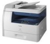
Service Manual MF6500 Series imageCLASS MF6530 Apr 22 2006 - Canon MF6530 | Service Manual - Page 2
- Canon MF6530 | Service Manual - Page 3
reserved. Under the copyright laws, this manual may not be copied, reproduced or translated into another language, in whole or in part, without the written consent of Canon Inc. COPYRIGHT © 2001 CANON INC. Printed in Japan Caution Use of this manual should be strictly supervised to avoid disclosure - Canon MF6530 | Service Manual - Page 4
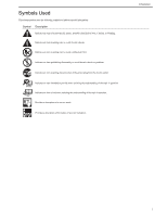
(fire). Indicates an item prohibiting disassembly to avoid electric shocks or problems. Indicates an item requiring disconnection of the power plug from the electric question. REF. Provides a description of a service mode. Provides a description of the nature of an error indication. Introduction i - Canon MF6530 | Service Manual - Page 5
sensors to the input of the DC controller PCB and from the output of the DC controller PCB to the loads. The descriptions in this Service Manual are subject to change without notice for product improvement or other purposes, and major changes will be communicated in the form of - Canon MF6530 | Service Manual - Page 6
- Canon MF6530 | Service Manual - Page 7
by the User ...1- 14 1.2.4.1 User Maintenance Items...1- 14 1.2.4.2 Cleaning ...1- 14 1.2.5 Safety ...1- 16 1.2.5.1 Safety of the Laser Light...1- 16 1.2.5.2 Safety of Toner...1- 16 1.2.5.3 CDRH Regulations ...1- 16 1.2.5.4 Handling the Laser Unit ...1- 16 1.2.5.5 Point to Note about Fire...1- 17 - Canon MF6530 | Service Manual - Page 8
Diagram ...2- 2 2.1.3 Image Processor PCB ...2- 2 (if equipped with network functions 2- 4 2.1.10 NCU PCB (if equipped with fax functions Parts Replacement Procedure ...3- 6 3.4.1 Copyboard Glass...3- 6 3.4.1.1 Removing the Copyboard Glass ...3- 6 3.4.2 Analog Processor PCB...3- 6 3.4.2.1 Removing - Canon MF6530 | Service Manual - Page 9
Paper Pickup Operation ...4- 4 4.2.4 Reversal Operation ...4- 4 4.2.5 Delivery Operation...4- 5 4.3 Detection Jams ...4- 7 4.3.1 Outline ...4- 7 4.4 ADF...4- 8 4.4.1 ADF ...4- 8 4.4.1.1 Removing the ADF ...4- 8 4.4.2 External Covers...4- 8 4.4.2.1 Removing the Front Cover...4- 8 4.4.2.2 Removing - Canon MF6530 | Service Manual - Page 10
5.1.1 Specifications and Control Mechanism 5- 1 5.1.2 Main Components...5- 2 5.2 Parts Replacement Procedure ...5- 3 5.2.1 Laser/Scanner Unit ...5- 3 5.2.1.1 Removing the Laser Scanner Unit 5- 3 Chapter 6 Image Formation 6.1 Overview/Configuration ...6- 1 6.1.1 Specifications and Control Mechanism - Canon MF6530 | Service Manual - Page 11
Contents 7.6.7.1 Removing the Manual Tray Sensor 7- 8 7.6.8 Manual Pickup Solenoid ...7- 8 7.6.8.1 Removing the Manual Pickup Solenoid 7- 8 7.6.9 Manual Separation Roller ...7- 8 7.6.9.1 Removing the Manual Separation Pad 7- 8 7.6.10 Registration Roller ...7- 8 7.6.10.1 Removing the Registration - Canon MF6530 | Service Manual - Page 12
9.4 Parts Replacement Image Processor PCB 9- 8 9.4.7 DC Controller PCB ...9- 9 9.4.7.1 Removing the DC Controller PCB 9- 9 9.4.8 Powwer Supply PCB...9- 9 9.4.8.1 Removing the Power Supply PCB 9- 9 9.4.9 Relay PCB ...9- 9 9.4.9.1 Removing the Relay PCB...9- 9 9.4.10 NCU PCB...9- 9 9.4.10.1 Removing - Canon MF6530 | Service Manual - Page 13
Contents Chapter 10 Maintenance and Inspection 10.1 Periodically Replaced Parts...10- 1 10.1.1 Periodically Replaced Parts...10- 1 10.2 Consumables ...10- 1 10.2.1 Durables...10- 1 10.3 Periodical Service...10- 1 10.3.1 Periodeical Service Items...10- 1 Chapter 11 Measurement and Adjustments 11.1 - Canon MF6530 | Service Manual - Page 14
of Error Codes...13- 1 13.2 Jam Code...13- 2 13.2.1 Jam Codes (Main body)...13- 2 13.2.2 Jam Codes (ADF) ...13- 2 13.3 Fax Error Codes...13- 2 13.3.1 Outline ...13- 2 13.3.1.1 Error Code Outline...13- 2 13.3.2 User Error Code ...13- 3 13.3.2.1 User Error Code ...13- 3 13.3.3 Service Error Code...13 - Canon MF6530 | Service Manual - Page 15
-ID code 14- 13 14.5.5 - Canon MF6530 | Service Manual - Page 16
(manual feed tray 14- 18 14.7.2.10 < Clearing Counters...14- 19 14.9 Report Output (REPORT) ...14- 20 14.9.1 Report Output...14- 20 14.9.2 System Data List...14- 20 14.9.3 System Dump List...14- 21 14.9.4 Counter List ...14- 22 14.9.5 Error Log List ...14- 23 14.9.6 Spec List...14- 24 14.9.7 Service - Canon MF6530 | Service Manual - Page 17
ROLLER CLEAN 14- 37 Chapter 15 Upgrading 15.1 Outline ...15- 1 15.1.1 Overview of Upgrade ...15- 1 15.1.2 Overview of Service Support Tool ...15- 1 15.2 Making Preparations ...15- 1 15.2.1 Registering the System Software ...15- 1 15.2.2 Connection ...15- 3 15.3 Downloading System Software ...15 - Canon MF6530 | Service Manual - Page 18
- Canon MF6530 | Service Manual - Page 19
Chapter 1 Introduction - Canon MF6530 | Service Manual - Page 20
- Canon MF6530 | Service Manual - Page 21
Maintenance by the User...1-14 1.2.4.1 User Maintenance Items...1-14 1.2.4.2 Cleaning ...1-14 1.2.5 Safety...1-16 1.2.5.1 Safety of the Laser Light...1-16 1.2.5.2 Safety of Toner...1-16 1.2.5.3 CDRH Regulations ...1-16 1.2.5.4 Handling the Laser Unit...1-16 1.2.5.5 Point to Note about Fire ...1-17 - Canon MF6530 | Service Manual - Page 22
- Canon MF6530 | Service Manual - Page 23
1.1 System Construction 1.1.1 System Construction [1] [2] [3] [1] Host machine [2] Cassette Unit-M1 [3] Hand Set CT-25 F-1-1 T-1-1 Chapter 1 0011-4306 1-1 - Canon MF6530 | Service Manual - Page 24
Copy+Printer+Scan+Fax+ADF+NW 0564B029AA T-1-2 Model name imageCLASS MF6530 imageCLASS MF6531 LaserBase MF6530 LaserBase MF6540PL imageCLASS MF6550 LaserBase MF6550 imageCLASS MF6550 imageCLASS MF6550 imegeCLASS MF6550 LaserBase MF6560PL imageCLASS MF6560 Satera MF6570 imageCLASS MF6570 imageCLASS - Canon MF6530 | Service Manual - Page 25
of Parts 1.2.1.1 External View (Front) [1] [2] [3] [4] [8] [9] [10] [11] Chapter 1 0011-3526 [7] [6] [5] [12] F-1-2 T-1-3 [1] Open/close cover [7] Cassette [2] Slide guide [8] Left cover [3] Document feeder tray [9] Scanning glass [4] Document delivery tray [10] White - Canon MF6530 | Service Manual - Page 26
] [20] [19] [18] [17] [16] [15] [14] [13] [12] [11] [10] [9] [8] [7] [6] F-1-4 T-1-5 [1] Reading glass [12] Vertical path roller [2] CS unit [13] Registration roller [3] Toner cartridge [14] Developing cylinder [4] Laser scanner unit [15] Transfer charging roller [5] Copyboard - Canon MF6530 | Service Manual - Page 27
[3] Separation pad [6] Delivery roller Chapter 1 1-5 - Canon MF6530 | Service Manual - Page 28
Chapter 1 1.2.2 Using the Machine 1.2.2.1 Turning On the Power Switch 0011-4257 The machine possesses 2 power switches: main power switch and control power switch. Normally (i.e., unless the machine is in a sleep state), the machine will be supplied with power when you turn on its main power switch. - Canon MF6530 | Service Manual - Page 29
1.2.2.2 When Turning Off the Main Power Switch Be sure to operate the main power switch while the Processing/Data lamp on the control panel is not lit. (Turning off the main switch during printing or fax data transmission/reception can erase the - Canon MF6530 | Service Manual - Page 30
Chapter 1 Do not turn off the power switch or ON/OFF switch on the control panel. (Turning off the main power switch during downloading can make this machine inoperative.) F-1-8 1-8 - Canon MF6530 | Service Manual - Page 31
[27] [Density] button [28] [Image Quality] button [29] [Paper Select] button [1] [2] [3] [4] [5] [6] Panel open [7] [8] [7] F-1-10 [1] [Direct TX] button [2] [Pause] button [3] [Hook] button [4] [Redial] button [5] [Coded Dial] button [6] [Address Book] button - Canon MF6530 | Service Manual - Page 32
ERROR ONLY (volume 1(*) to 3), OFF, ON (volume 1(*) to 3) PRINT DONE TONE: ERROR ONLY (volume 1(*) to 3), OFF, ON (volume 1(*) to 3) 4. TONER SAVER MODE OFF(*), ON 5. PRINTER 200% MAX., 50% MIN., 64%, 70% A4->A5, 73% 11X17->LGL, 78% LGL->LTR, 81% B5->A5, 86% A4->B5), MANUAL COPIES: 1(*) to 99 AUTO - Canon MF6530 | Service Manual - Page 33
3. COPIES 4. 2-SIDED PRINTING 5. PRINT QUALITY 6. PAGE LAYOUT 7. ERROR TIME OUT 8. COLLATE Available Settings LTR(*), STMT, EXECUTIV, ISO-B5, COM10, MONARCH, DL, A4, B5, A5, LGL PLAIN PAPER(*), COLOR, RECYCLED, HEAVY PAPER 1, HEAVY PAPER 2, HEAVY PAPER 3, 3 HOLE PUNCH PAPER, BOND, TRANSPARENCY - Canon MF6530 | Service Manual - Page 34
MODE O 7. SPECIAL MODE P 8. SPECIAL MODE Q 9. SPECIAL MODE R 10.SPECIAL MODE S 11. CONT PRINT MODE 12. BACK EDGE MODE 13.LARGE PAPER MODE 14. AUTO ADF DRTY ADJ 15. MAINTENANCE CODE Available Settings Press [OK] to start cleaning. START CLEANING, CLEAN PAPER PRT Set 5 sheets in the optional feeder - Canon MF6530 | Service Manual - Page 35
MAC ADD SET. (OFF(*), ON) SNMP SETTINGS: USE SNMP (ON(*): PORT NO., OFF), COMMUNITY NAME 1, COMMUNITY NAME 2, SNMP WRITABLE 1 (ON(*), OFF), SNMP WRITABLE 2 (ON, OFF(*)) DEDICATED PORT: ON(*), OFF ETHERNET DRIVER: AUTO DETECT (AUTO(*), MANUAL), DUPLEX (HALF DUPLEX(*), FULL DUPLEX), ETHERNET TYPE (10 - Canon MF6530 | Service Manual - Page 36
cleaning As required [7] Toner cartridge replacement When the message appears 1.2.4.2 Cleaning 0012-7146 The parts that should be cleaned by the customer to maintain the design performance and the cleaning method are described below. The service engineer should instruct the customer to clean - Canon MF6530 | Service Manual - Page 37
tray. 6) Place an A4 or LTR sheet of plain paper in the manual feed tray. Chapter 1 F-1-13 7) Press the OK key. The machine will start cleaning the fixing pressure roller. 4.Cleaning the Transfer roller If the reverse side of the printed paper is stained, the transfer roller can be dirty. If the - Canon MF6530 | Service Manual - Page 38
J. F-1-14 1.2.5.4 Handling the Laser Unit 0011-3533 The laser scanner unit emits invisible laser light inside it. If exposed to laser light, the human eye can irreparably be damaged. Never attempt to disassemble the laser scanner unit. (It is not designed for servicing in the field.) Warning labels - Canon MF6530 | Service Manual - Page 39
containing flammable substances, such as cartridges, etc., into fire. Such parts and components must be disposed of in accordance with local laws and regulations. 1.2.5.6 Cautions as to the replacement and disposal of lithium battery 0011-3536 The machine's image processor is equipped with a fixed - Canon MF6530 | Service Manual - Page 40
care not to drop it.) T-1-9 Temperature Normal (9/10 of total storage period) 0 to 35 deg C Severe (1/10 of total storage time) High 35 to 40 light. It is also used to hold toner inside it. Be sure to advise the user to be fully careful when storing and handling the cartridge. (The cartridge - Canon MF6530 | Service Manual - Page 41
First print time Cassette paper size dual processing by cleaning blade SURF (on-demand) by toner cartridge magnetic negative toner yes Sheet, book, 3-D object (2 kg max.) LGL (356 X 216mm) A series: 2R2E (1:1.000, 1:0.500, 1:0.70, 1:0.41, 1:2.000) INCH series: 3R2E (1:1.000, 1:0.500, 1:0.64, 1:0.78 - Canon MF6530 | Service Manual - Page 42
manually ON/OFF; auto OFF after specific time, auto ON after fax reception/print data reception) Operating environment (temperature range) Operating environment (humidity range) Operating environment (atmospheric pressure) Noise 15 to 30 deg C 10 toner cartridge ) Same types of paper can be mixed. - Canon MF6530 | Service Manual - Page 43
. Image memory type: SDRAM Storage method: JBIG Backup battery: rechargeable capacitor Backup length: 1 hr (approx.) 1.2.7 Function List 1.2.7.1 Printing Speed T-1-10 0011-4260 Type Single-sided Two-sided Cassette feed Manual feed Cassette feed Manual feed Plain paper, colored paper, A4R - Canon MF6530 | Service Manual - Page 44
paper Colored paper Heavy paper 1 Heavy paper 2 Heavy paper 3 Bond 3hole punch paper Transparency Labels Envelopes Cassette A4 (For JP/KOR/EU/ASIA/OCE) LGL/LTR/OFICIO/BOFI/M-OFI/ FOOLSCAP (for USA/CA/LA) 16K/A4(for CHN) 64 to 90 g/m2 Max. 500 sheets Yes Yes Yes Yes No No Yes Yes No No No Manual - Canon MF6530 | Service Manual - Page 45
Chapter 1 1-23 - Canon MF6530 | Service Manual - Page 46
- Canon MF6530 | Service Manual - Page 47
Chapter 2 Basic Operation - Canon MF6530 | Service Manual - Page 48
- Canon MF6530 | Service Manual - Page 49
2.1.2 Functional Block Diagram ...2-2 2.1.3 Image Processor PCB...2-2 2.1.4 DC Controller PCB ...2-3 2.1.5 Analog Processor PCB ...2-4 2.1.6 Power Supply PCB...2-4 2.1.7 Relay PCB ...2-4 2.1.8 Control Panel PCB ...2-4 2.1.9 Network PCB (if equipped with network functions) ...2-4 2.1.10 NCU PCB (if - Canon MF6530 | Service Manual - Page 50
- Canon MF6530 | Service Manual - Page 51
Delivery tray Fixing unit Image formation Cleaner system Aassembly Transfer charging roller Drum Developing assembly Laser driver PCB Laser scanner assembly Laser exposure system Multi feeder tray Casstte Casstte (Option) *1 : If equipped with printer functions. *2 : If equipped with - Canon MF6530 | Service Manual - Page 52
while the machine isin standby state. Memory Storage Image data is stored in SDRAM, and is retained for about 1 hr even after the power is removed by the work of the super capacitor mounted on the modem PCB. The system software and various data (e.g., user data, service data) are held by - Canon MF6530 | Service Manual - Page 53
motor is controlled so that the horizontal resolution of the print image is 600 dpi. Also, the laser beam detection signal (BDI*) from the laser scanner unit is detected to monitor the rotation of the scanner motor. Cartridge Detection Mechanism In wait state, the CPU on the DC controller PCB - Canon MF6530 | Service Manual - Page 54
during normal rotation to monitor the toner level inside the cartridge. 2.1.5 Analog Processor PCB 0011-3551 Image Processing Control Block The analog image data read by the contact sensor is converted into digital image data and sent to the ASIC of the image processor PCB. Drive Control Block The - Canon MF6530 | Service Manual - Page 55
the other hand, demodulates data received from the line according to ITU-T V.17, V.21, V.27ter, V.29, or V.34. Super Capacitor Backs up the transmission/reception image data stored in SDRAM. DC/DC When the main power is off (e.g., in the event of power failure), increases the voltage of the super - Canon MF6530 | Service Manual - Page 56
, thereby forming a latent image on the photosensitive drum and turning it into a toner image. From when printing ends until the main motor stops. The drum surface is made free of potential and the transfer charging roller is cleaned. After last rotation, the machine shifts to standby to wait for - Canon MF6530 | Service Manual - Page 57
Chapter 2 2-7 - Canon MF6530 | Service Manual - Page 58
- Canon MF6530 | Service Manual - Page 59
Chapter 3 Original Exposure System - Canon MF6530 | Service Manual - Page 60
- Canon MF6530 | Service Manual - Page 61
Horizontal Scan Direction...3-3 3.3.2 Dirt Sensor Control ...3-3 3.3.2.1 Outline...3-3 3.4 Parts Replacement Procedure ...3-6 3.4.1 Copyboard Glass ...3-6 3.4.1.1 Removing the Copyboard Glass ...3-6 3.4.2 Analog Processor PCB ...3-6 3.4.2.1 Removing the Analog Processor PCB ...3-6 3.4.3 Reader Motor - Canon MF6530 | Service Manual - Page 62
- Canon MF6530 | Service Manual - Page 63
T-3-1 0012-7060 Item Function/Method Exposure light source LED Original scan In BOOK mode: image data. The image reading mechanism is controlled based on the drive signals from the image processor PCB, thereby moving the contact sensor to read the original placed on thecopyboard glass - Canon MF6530 | Service Manual - Page 64
Chapter 3 3.2 Basic Sequence 3.2.1 Basic Sequence at Power-on 0012-7070 Main power switch ON Reader motor (M401) LED SREADY STBY CS HP sensor (SR401) Shading position Shading position F-3-2 : Forward movement : Backward movement CSHP sensor Shading Leading edge HP position of original - Canon MF6530 | Service Manual - Page 65
on the selected magnification rate. Data is not processed on the image processor PCB. 3.3.2 Dirt Sensor Control 3.3.2.1 Outline 0012-7080 The machine changes the original read position or corrects the read image depending on the presence/absence of dust on the stream reading glass or ADF platen 3-3 - Canon MF6530 | Service Manual - Page 66
contact sensor (CS) checks the light reflected by the ADF platen guide surface at the read position for glass cleaning message in the control panel. 0.5mm 0.5mm ABC Reading glass lens Platen guide LED Contact sensor F-3-9 - Immediately before scanning (one sheet at a time) The contact image - Canon MF6530 | Service Manual - Page 67
Point C Description About 1.0 mm from the reference position to the inside of the guide Chapter 3 3-5 - Canon MF6530 | Service Manual - Page 68
screws [2], and one connector [3]. [2] [2] [4] F-3-10 Take care not to touch the contact sensor[4] when removing the copyboard glass [3]. 3.4.2 Analog Processor PCB 3.4.2.1 Removing the Analog Processor PCB 0011-5278 MEMO: This machine stores adjustment values in the image processor PCB, not the - Canon MF6530 | Service Manual - Page 69
perform inter-channel output correction: 1) Enter the service mode. Sequentially press the Additional functions key, 2 Removing the Contact Sensor Home Position Sensor 0011-5283 1) Remove the copyboard glass. 2) Remove the two screws [1] and remove the glass retainer [2]. 3) Remove the reading glass - Canon MF6530 | Service Manual - Page 70
- Canon MF6530 | Service Manual - Page 71
Chapter 4 Original Feeding System - Canon MF6530 | Service Manual - Page 72
- Canon MF6530 | Service Manual - Page 73
Document Size Detection...4-4 4.2.3 Paper Pickup Operation...4-4 4.2.4 Reversal Operation...4-4 4.2.5 Delivery Operation...4-5 4.3 Detection Jams...4-7 4.3.1 Outline...4-7 4.4 ADF ...4-8 4.4.1 ADF...4-8 4.4.1.1 Removing the ADF ...4-8 4.4.2 External Covers ...4-8 4.4.2.1 Removing the Front Cover - Canon MF6530 | Service Manual - Page 74
- Canon MF6530 | Service Manual - Page 75
far as stream reading position, read by the contact sensor (for collection of analog image data), and sent to the delivery assembly. The ADF has 4 sensors to monitor of an original in the document set assembly. Detects the paper feed status and triggers scanning. Detects the timing at which the - Canon MF6530 | Service Manual - Page 76
for documents with the same width.) Picks up, reads, reverses, and delivers an document. Double-sided document > Duplex printing Double-sided document > Simplex printing (This operation is performed for documents with the same width.) MEMO: This operation is performed for all single-sided - Canon MF6530 | Service Manual - Page 77
[2] Forward Pickup/Reversal Delivery Operation The document flow is shown below. MEMO: This operation is performed for all double-sided documents irrespective of whether document widths are the same. Document Pickup Reversal Formation of loop Formation of loop Reading Reverse side reading - Canon MF6530 | Service Manual - Page 78
printing and banner paper printing are included.) The document feeder tray does not have a sensor for detecting the paper transport rollers rotate to feed the paper. The shutter moves up in conjunction with the paper along the platen guide for surface scanning. After completion of scanning, the paper - Canon MF6530 | Service Manual - Page 79
M2001 M2001 Chapter 4 SL2002 SL2003 SL2002 SL2003 Platen guide Registration roller F-4-7 b. Reversal/Feed 1 When the predetermined time has lapsed 0011-6139 The original finished with stream reading on the original glass is delivered to the original delivery unit as described below. 4-5 - Canon MF6530 | Service Manual - Page 80
(M2001). The delivery roller is normally held pressurized. It is released when the roller release solenoid (SL2003) turns on to reverse the original for duplex printing. M2001 M2001 SL2002 SL2003 SL2002 SL2003 Delivery roller - Canon MF6530 | Service Manual - Page 81
/absence of the document at the relevant sensor position. When a jam occurs, the host machine stores its code. Jam codes can be checked by outputting a jam error log report in the service mode of the host machine. SR2001 SR2004 SR2002 SR2003 Code 0000 0007 0008 0009 000a 000c 000f 0010 F-4-11 - Canon MF6530 | Service Manual - Page 82
[2] to disconnect the cable [3]. [2] [3] [1] [3] [2] [1] F-4-13 3) Open the ADF [1] vertically, and remove it by lifting upward. [1] F-4-15 4.4.2.2 Removing the Rear Cover 0011-5222 1) Remove the stopper screw [1]. 2) Open the pickup tray, remove the screw [2], and then detach the rear cover - Canon MF6530 | Service Manual - Page 83
and rear shafts [2] of the open/close cover, and then detach this cover [3]. F-4-17 4.4.2.4 Removing the Pickup Tray 0011-5227 1) Detach the open/close cover, or open the open/close cover by removing the open/close cover stopper. 2) Remove the left and right shafts [1] of the pickup tray, and then - Canon MF6530 | Service Manual - Page 84
F-4-22 4.4.5 Pick-up/Feed Roller Unit 4.4.5.1 Removing the Pickup/Feed Roller Unit 0011-5230 1) Remove the open/close cover. 2) Remove the shafts, and then remove the two shutters [1]. 3) Press the support plate with your fingers to remove the shaft [2], and then remove the pickup/feed roller unit - Canon MF6530 | Service Manual - Page 85
After replacing the ADF motor unit, reinstall the parts removed in steps 3) and 4). 4.4.9 Document Set Sensor 4.4.9.1 Removing the Document Set Sensor 0011-5254 1) Remove the rear cover. 2) Remove the connector [1], release the hook, and then remove the document set sensor [2]. [2] [1] F-4-29 4-11 - Canon MF6530 | Service Manual - Page 86
Sensor 4.4.10.1 Removing the document Edge Sensor 0011-6037 1) Detach the front cover and open/close cover. 2) Open the ADF, remove the three screws [1], and then detach the ADF left [2] lower cover [2]. [1] [1] F-4-33 4) Disconnect the connector [1], release the hook, and then remove the - Canon MF6530 | Service Manual - Page 87
close cover. 2) Release the two claws [1], and then remove the separation pad [2]. [1] [2] [2] F-4-38 3) Remove the screw [1], and then remove the registration solenoid [2]. [2] [1] [1] F-4-41 F-4-39 4.4.15 Release Solenoid 4.4.15.1 Removing the Roller Release Solenoid 0011-5243 1) Detach the - Canon MF6530 | Service Manual - Page 88
Chapter 4 4-14 - Canon MF6530 | Service Manual - Page 89
Chapter 5 Laser Exposure - Canon MF6530 | Service Manual - Page 90
- Canon MF6530 | Service Manual - Page 91
Contents Contents 5.1 Overview/Configuration ...5-1 5.1.1 Specifications and Control Mechanism...5-1 5.1.2 Main Components ...5-2 5.2 Parts Replacement Procedure ...5-3 5.2.1 Laser/Scanner Unit...5-3 5.2.1.1 Removing the Laser Scanner Unit ...5-3 - Canon MF6530 | Service Manual - Page 92
- Canon MF6530 | Service Manual - Page 93
Overview/Configuration 5.1.1 Specifications and Control Mechanism T-5-1 Item Laser beam Number of laser beams Scanner Motor Type of motor Rotation control Polygon Mirror Number of facets Control Mechanism Synchronous control Light intensity control Others Description 2 beams DC brushless motor - Canon MF6530 | Service Manual - Page 94
and forming static images. - copy image data - print image data (if equipped with printer functions) - fax image data (if equipped with fax functions) Image processor PCB Horizontal sync signal (BDO*) Laser driver control signal (CTRL0, CTRL1, CTRL2 Communication control Laser scanner motor drive - Canon MF6530 | Service Manual - Page 95
5.2 Parts Replacement Procedure 5.2.1 Laser/Scanner Unit 5.2.1.1 Removing the Laser Scanner Unit 0011-5287 The laser scanner was-factory adjusted. Never disassemble it. 1) Detach the right cover, inner cover, delivery tray front cover, control panel, and delivery tray. 2) Remove the laser shutter - Canon MF6530 | Service Manual - Page 96
- Canon MF6530 | Service Manual - Page 97
Chapter 6 Image Formation - Canon MF6530 | Service Manual - Page 98
- Canon MF6530 | Service Manual - Page 99
Contents 6.1 Overview/Configuration ...6-1 6.1.1 Specifications and Control Mechanism...6-1 6.2 Image Formation Process ...6-1 6.2.1 Reproduction Processes...6-1 6.3 Parts Replacement Procedure ...6-3 6.3.1 Transfer Charging Roller ...6-3 6.3.1.1 Removing the Transfer Charging Roller...6-3 - Canon MF6530 | Service Manual - Page 100
- Canon MF6530 | Service Manual - Page 101
as shown below Copyboard glass Chapter 6 0012-7116 0012-7057 Contact sensor Fixing unit Cleaning blade Image processing block Primary charging roller Laser scanner unit Drum Static eliminator Transfer charging roller Developing cylinder Cartridge Paper Paper F-6-1 The machine is - Canon MF6530 | Service Manual - Page 102
Chapter 6 4. Fixing block 6. fixing Delivery 7.drum cleaning 5. Drum cleaning block 3. Transfer block 5. separation 4. transfer 1. primary charging 2. laser beam exposure 1. Latent image formation block Multifeeder [1] Latent Image Formation Block Step 1 primary charging (AC + negative DC) - Canon MF6530 | Service Manual - Page 103
6.3 Parts Replacement Procedure 6.3.1 Transfer Charging Roller 6.3.1.1 Removing the Transfer Charging Roller 0011-5296 1) Remove the cartridge. 2) Release the two hooks [1], and then remove the transfer charging roller [2]. [2] [1] F-6-3 Chapter 6 6-3 - Canon MF6530 | Service Manual - Page 104
- Canon MF6530 | Service Manual - Page 105
Chapter 7 Pickup and Feed System - Canon MF6530 | Service Manual - Page 106
- Canon MF6530 | Service Manual - Page 107
the Size of Paper ...7-3 7.4 Duplex Unit ...7-4 7.4.1 Outline...7-4 7.5 Manual Feed Pickup Unit ...7-5 7.5.1 Outline...7-5 7.5.2 Retry Pickup...7-5 7.5.3 Detecting the Size of Paper ...7-5 7.6 Parts Replacement Procedure ...7-6 7.6.1 Cassette Pickup Roller ...7-6 7.6.1.1 Removing the Cassette Pickup - Canon MF6530 | Service Manual - Page 108
- Canon MF6530 | Service Manual - Page 109
moves centered through the pickup/feeding/delivery path. The source of paper may be from any of two: cassette and manual feed tray. The paper is controlled so that its leading edge matches the leading edge of the image on the photosensitive drum by means of the registration sensor (SR11); it then is - Canon MF6530 | Service Manual - Page 110
does not detect the trailing edge of paper within a specific period of time. Wound Paper Jam at Fuser The delivery sensor (SR5) has detected absence of paper within the prescribed time after it detected presence of paper. Initial Jam - When presence of paper is detected by the registration sensor - Canon MF6530 | Service Manual - Page 111
specified value and the delivery paper full sensor (SR10) turns on, this machine detects occurrence of an error and displays an error message on the LCD. as a jam and will indicate a jam message on the LCD of its control panel. 7.3.3 Detecting the Size of Paper 0011-4055 The cassette paper size - Canon MF6530 | Service Manual - Page 112
main motor (M1) under the control of the CPU installed on the DC controller PCB. When the trailing edge of the paper finished with printing on its top surface reaches the point 10 mm away from the delivery sensor (SR5), the duplex drive solenoid (SL1) turns on and the drive power of the - Canon MF6530 | Service Manual - Page 113
value and the delivered paper full sensor (SR10) turns on, this machine detects occurrence of an error and displays an error message on the LCD. jam and will indicate a jam message on the LCD in its control panel. 7.5.3 Detecting the Size of Paper 0011-4059 The size of paper in the manual - Canon MF6530 | Service Manual - Page 114
, remove the boss [2] and slide the feed roller upward until the shafts [3] are separated. 4) Pull out the feed roller [4] to remove it. [2] [1] F-7-10 7.6.3 Cassette Paper Sensor 7.6.3.1 Removing the Cassette Paper Sensor 0011-5385 1) Remove the two shafts [1], and then remove the transfer guide - Canon MF6530 | Service Manual - Page 115
, and then remove the cassette paper sensor [2]. [2] [1] [1] [3] [4] F-7-15 5) Remove the bushing [1] and shaft [2], and then remove the feed roller [3]. [2] [1] [3] F-7-16 7.6.6 Manual Pickup Roller F-7-13 7.6.4 Cassette Pickup Solenoid 7.6.6.1 Removing the Manual Pickup Roller 0011 - Canon MF6530 | Service Manual - Page 116
rear-left cover. 2) Disconnect the connector [1], remove the screw [2], and then remove the manual tray pickup solenoid [3]. F-7-22 7.6.10 Registration Roller 7.6.10.1 Removing the Registration Roller 0011-5378 1) Remove the rear cover and rear-left cover. 2) Remove the fun duct, main motor, relay - Canon MF6530 | Service Manual - Page 117
[1] and move the guide [2] out of the way. 7) Remove the drum shutter lever 1/2 [3]. [2] [3] [3] F-7-26 7.6.11 Registration Sensor 7.6.11.1 Removing the Registration Sensor 0011-5383 1) Remove the two shafts [1], and then remove the transfer guide [2]. [1] F-7-24 8) Remove one E-ring [1], two - Canon MF6530 | Service Manual - Page 118
fixing/drive unit. 3) Remove the screw [1], and then remove the duplex pickup solenoid [2]. 7-10 [1] [2] F-7-33 7.6.14 Main Motor 7.6.14.1 Removing the Main Motor 0011-5476 1) Detach the rear cover. 2) Remove the screw [1], and then remove the fan duct[2]. 2) Remove the three screws [3], and - Canon MF6530 | Service Manual - Page 119
[5] [4] [1] [2] [3] F-7-34 Chapter 7 7-11 - Canon MF6530 | Service Manual - Page 120
- Canon MF6530 | Service Manual - Page 121
Chapter 8 Fixing System - Canon MF6530 | Service Manual - Page 122
- Canon MF6530 | Service Manual - Page 123
Failure Detection ...8-3 8.4 Parts Replacement Procedure ...8-5 8.4.1 Fixing Unit ...8-5 8.4.1.1 Removing the Fixing Unit Removing the Fixing Film Unit ...8-7 8.4.3 Fixing Pressure Roller...8-8 8.4.3.1 Removing the Pressure Roller...8-8 8.4.4 Fixing Delivery Paper Sensor ...8-8 8.4.4.1 Removing - Canon MF6530 | Service Manual - Page 124
- Canon MF6530 | Service Manual - Page 125
of error in toner is fused to the paper by the work of the fixing film and the fixing pressure roller. The delivery sensor (SR5) is used to detect paper coming out of the fixing assembly. Delivery roller Delivery sensor (SR5) Fixing film Fixing pressure roller Fixing heater Fixing inlet guide - Canon MF6530 | Service Manual - Page 126
is used to detect an error temperature on the end of paper: 270 mm or longer Small-size paper: 215.9 mm or longer T-8-2 Print count (sheets) Heater cooling time (s) After printing on small-size paper. 1-10 11-20 21 and more 0 5 10 After the throughput of printing on large-size paper - Canon MF6530 | Service Manual - Page 127
mode and target temperature is as follows: T-8-3 Paper type Cassette Manual pickup feed tray pickup Duplex Fixing mode Target unit J113 GND -4 SUBTH -3 GND -2 MAINTH -1 Fixing heater high temperature error detection TH2 TH1 J25 -1 TP -2 H1 F-8-3 8.3.2 Failure Detection 0011-4251 The - Canon MF6530 | Service Manual - Page 128
75deg C even if 2.29 to 20 seconds have lapsed since start of power supply to the fixing heater. c. Detection of Drive circuit failure (zero-cross error) This failure is detected when the number (cycle) of zero-cross inputs that have been counted every second has been outside the range (45-65 - Canon MF6530 | Service Manual - Page 129
8.4 Parts Replacement Procedure 8.4.1 Fixing Unit 8.4.1.1 Removing the Fixing Unit 0011-5386 The height left cover. 2) Remove the boss [1], and then slide the guide (front) [2] to remove it. [1] Chapter 8 [1] F-8-6 4) Remove the screw [1] and remove the fan duct [2]. 5) Remove the three connectors - Canon MF6530 | Service Manual - Page 130
installing a new fixing unit, install the positioning pin to align with reference mark [3]. F-8-10 9) Apply marking [1], remove 4 screws [2], and detach the fixing unit [3]. [3] [1] [2] F-8-12 4) Remove the positioning pin. 5) Install positioning pin [2] to align with marking [1] at the front - Canon MF6530 | Service Manual - Page 131
procedure by reversing the installation procedure. 8.4.2 Fixing Film Unit 8.4.2.1 Removing the Fixing Film Unit 0011-5388 1) Remove the fixing unit. 2) Remove the three screws [1], and then remove the reversing guide [2] and sensor lever unit [3]. [1] [3] [2] F-8-15 See the illustration below - Canon MF6530 | Service Manual - Page 132
8.4.4 Fixing Delivery Paper Sensor 8.4.4.1 Removing the Delivery Sensor 0011-5390 1) Remove the front cover and front-left cover. 2) Remove the boss [1], and then slide the guide (front) [2] upward to remove it. [1] [1] F-8-20 4) Release the hook and remove the gear [1]. The remaining part is the - Canon MF6530 | Service Manual - Page 133
8.4.5 Delivery Full Sensor 8.4.5.1 Removing the Delivery Full Sensor 0011-5391 1) Remove the fixing unit. 2) Disconnect the connector [1], and then remove the delivery full sensor [2] with the hook released. [2] [1] F-8-25 Chapter 8 8-9 - Canon MF6530 | Service Manual - Page 134
- Canon MF6530 | Service Manual - Page 135
Chapter 9 External and Controls - Canon MF6530 | Service Manual - Page 136
- Canon MF6530 | Service Manual - Page 137
9.4 Parts Replacement Image Processor PCB...9-8 9.4.7 DC Controller PCB ...9-9 9.4.7.1 Removing the DC Controller PCB ...9-9 9.4.8 Powwer Supply PCB...9-9 9.4.8.1 Removing the Power Supply PCB ...9-9 9.4.9 Relay PCB ...9-9 9.4.9.1 Removing the Relay PCB ...9-9 9.4.10 NCU PCB...9-9 9.4.10.1 Removing - Canon MF6530 | Service Manual - Page 138
Contents 9.4.15 Fan...9-10 9.4.15.1 Removing the Heat Discharge Fan ...9-10 9.4.16 Speaker ...9-11 9.4.16.1 Removing the Speaker...9-11 - Canon MF6530 | Service Manual - Page 139
of the image processor PCB. Image processor laser scanner unit and electric elements on PCBs. The fan is controlled by the CPU on the DC controller PCB. Its operating conditions are as follows: 1. During normal rotation, in the fixing cleaning mode (user mode), or after paper - Canon MF6530 | Service Manual - Page 140
CPU to detect that the left door has opened. T-9-1 Part Name Power supply PCB Main power switch (SW1) Interlock 24VR Laser scanner unit Interlock switch (SW2) Main motor Sensors Cassette unit*3 Analog processor PCB +3.3V +5V Image processor Output voltage tolerance +10%, -5% Rated output - Canon MF6530 | Service Manual - Page 141
like on the load side. If the over-current/over-voltage protective mechanism has gone ON, disconnect the power cord, and correct the fault; then, connect the power cord once gain to reset the machine. If short circuiting and resetting are repeated, the internal fuse (F1, F2) can melt. 9-3 - Canon MF6530 | Service Manual - Page 142
Chapter 9 9.4 Parts Replacement Procedure 9.4.1 External Cover 9.4.1.1 Detaching the Reader Rear Cover (Small) 0011-5392 1) Remove the screw move the machine backward until the hooks are about 10 cm away from the edge of the desk and so on. 2) Remove the screw [1]. 3) Release the three claws[2] at - Canon MF6530 | Service Manual - Page 143
of the machine, and then detach the rear-left cover [3]. [1] [3] [2] F-9-10 9.4.1.8 Detaching the Right Cover 0011-5399 1) Detach the rear cover. 2) To cover. [2] F-9-9 9.4.1.7 Detaching the Reader Right Cover 0011-5398 1) Remove the reader rear cover, and then detach the rear cover and right - Canon MF6530 | Service Manual - Page 144
of the arrow, and then detach the righy cover [4] by releasing the three hooks [3] at the bottom. F-9-12 9.4.1.9 Detaching the Front Cover 0011-5400 1) Remove the cassette. 2) Using a flathead screwdriver, release the two claws [1] at the right and four hooks [2] at the top. 3) By releasing the two - Canon MF6530 | Service Manual - Page 145
clutch. 3) Release the cable from all clamps on the pickup drive unit. 4) Remove the three screws [1], and then remove the pickup drive unit [2]. [1] [2] F-9-13 9.4.1.10 Detaching the Delivery Tray 0011-5401 1) Remove the rear cover, the front cover, the right cover, the reader rear cover and - Canon MF6530 | Service Manual - Page 146
If you have replaced the image processor PCB with a new one, perform the following operations: - Using the service support tool, download the latest firmware (System/Boot/ PCL*1) and language files. *1: if equipped with PCL functions - Input the all value printed on the service label affixed to the - Canon MF6530 | Service Manual - Page 147
. If automatic adjustment fails, "NG" appears. Perform the following procedure: Clean the platen guide of the DADF and the document glass of the host machine, and then retry auto adjustment. 9.4.7 DC Controller PCB 9.4.7.1 Removing the DC Controller PCB 0011-5464 1) Detach the right cover, inner - Canon MF6530 | Service Manual - Page 148
remove the cable from the cable guide by cutting cable ties. 3) Release the two claws [1], and then remove the interlock switch [2]. [2] [1] [2] [1] F-9-29 9.4.13 Network PCB 9.4.13.1 Removing Remove the three screws [2], and then remove the shield [3]. 9.4.15 Fan F-9-32 9.4.15.1 Removing the - Canon MF6530 | Service Manual - Page 149
[3] [2] [1] 9.4.16 Speaker F-9-33 9.4.16.1 Removing the Speaker 0011-5493 1) Detach the right cover and rear cover. 2) Disconnect the connector [1], and then remove the cable from the cable guide. [1] F-9-34 3) Remove the two screws [1], and then remove the speaker [2]. [2] [1] F-9-35 Chapter - Canon MF6530 | Service Manual - Page 150
- Canon MF6530 | Service Manual - Page 151
Chapter 10 Maintenance and Inspection - Canon MF6530 | Service Manual - Page 152
- Canon MF6530 | Service Manual - Page 153
Contents Contents 10.1 Periodically Replaced Parts ...10-1 10.1.1 Periodically Replaced Parts...10-1 10.2 Consumables...10-1 10.2.1 Durables ...10-1 10.3 Periodical Service ...10-1 10.3.1 Periodeical Service Items ...10-1 - Canon MF6530 | Service Manual - Page 154
- Canon MF6530 | Service Manual - Page 155
Parts 10.1.1 Periodically Replaced Parts The machine does not have parts that require periodical replacement. 10.2 Consumables 10.2.1 Durables The machine does not have durables. 10.3 Periodical Service 10.3.1 Periodeical Service Items The machine does not have periodecal service items. Chapter 10 - Canon MF6530 | Service Manual - Page 156
- Canon MF6530 | Service Manual - Page 157
Chapter 11 Measurement and Adjustments - Canon MF6530 | Service Manual - Page 158
- Canon MF6530 | Service Manual - Page 159
of the height of the fixing unit ...11-1 11.3 Electrical Adjustments...11-2 11.3.1 Procedure after Replacing the Image Processor PCB ...11-2 11.3.2 Actions to Take before All Clearing (Backing up the User Data 11-2 11.4 ADF ...11-3 11.4.1 Outline...11-3 11.4.1.1 Outline...11-3 11.4.1.2 Preparing - Canon MF6530 | Service Manual - Page 160
- Canon MF6530 | Service Manual - Page 161
following steps to perform inter-channel output correction: 1) Enter the service mode. Sequentially press the Additional functions key, 2 key, 8 the installation procedure. - The image at B (front side) is longer 1) Remove the 4 screws of the fuser unit. 2) Remove 1 screw and the positioning pin - Canon MF6530 | Service Manual - Page 162
If you have replaced the image processor PCB with a new one, perform the following operations: - Using the service support tool, download the latest firmware (System/Boot/ PCL*1) and language files. *1: if equiped with PCL functions. - Input the all value printed on the service label affixed to the - Canon MF6530 | Service Manual - Page 163
part. T-11-1 No. Adjustment type Replaced parts according to the sale markings so that the perpendicularity is within spec. Chapter 11 [1] service mode. (A4-size paper: 277 +/-1mm LTR paper: 59 +/-1mm) Image on copy A is shorter. -> Increase the value (or reduce the stream reading speed). Image - Canon MF6530 | Service Manual - Page 164
be set to the specified value using software, make adjustments again starting with the perpendicular adjustment. [1] F-11-10 MEMO: Making copies with the slide guide shifted 1 mm upward will increase the right registration (on the upper side of paper) by 1 mm. 11.4.3.3 Leading edge registration - Canon MF6530 | Service Manual - Page 165
Chapter 12 Correcting Faulty Images - Canon MF6530 | Service Manual - Page 166
- Canon MF6530 | Service Manual - Page 167
Contents Contents 12.1 Initial Checkup...12-1 12.1.1 Site Environment...12-1 12.1.2 Checking the Paper...12-1 12.1.3 Checking the Placement of Paper...12-1 12.1.4 Checking the Durables ...12-1 12.1.5 Checking the Units and Functional Systems...12-1 12.1.6 Others ...12-1 12.2 Outline of Electrical - Canon MF6530 | Service Manual - Page 168
- Canon MF6530 | Service Manual - Page 169
toner cartridge is installed securely. - Check whether the photoconductor drum guide is free from wear, scratches, dirt, and deformation. - Check whether the leading edge of paper is not folded, curled, wavy, or damp. - Check whether use of the Canon-recommended paper/transparency solves the problem - Canon MF6530 | Service Manual - Page 170
reader unit or on the copyboard glass can cause light images d. condensation on the pickup or feed guide can cause paper feed problems If the problem given in d. above has occurred, dry wipe the units in the feed system. Do not open the package containing a toner cartridge right after it has been - Canon MF6530 | Service Manual - Page 171
manual pickup roller. FK2-1411 Supplies a drive to each rollers. FK2-1413 Drives the laser scanner. FM2-5271 Drives the contact sensor. FK2-1383 Cools fixing unit. FK2-1386 Connection a drive to each rollers. Part No. FK2-1393 FK2-1393 FK2-1392 FK2-1384 Connection jack No. J411 (Analog - Canon MF6530 | Service Manual - Page 172
) Jam code 010c, 0210, 0214, 021c 0104, 0208, 010c, 0210, 0214 1118 SR10 SR401 SR12 SR9 SR5 SR11 SW2 12-4 Symbol SR2001 Name Document set sensor F-12-3 T-12-4 Function Detects presence/absence of paper. Part No. WG8-5696 Connection jack No. J406 (Analog processor PCB) Error 000a - Canon MF6530 | Service Manual - Page 173
, processes analog image data Printer power supply [5] Relay PCB Relay of drive system DC load [6] Laser driver PCB/BD detection PCB Laser drive/laser beam detection [7] NCU PCB Controls the line switching operation [8] Modular jack PCB Fax line interface [9] Modem PCB [10] LAN PCB - Canon MF6530 | Service Manual - Page 174
Chapter 12 [1] [10] [3] [6] [9] [7] [5] [8] [2] [4] [11] [12] - Canon MF6530 | Service Manual - Page 175
SP1 TH2 TH1 TP1 H1 There are no parts applicable to ADF. F-12-6 Chapter 12 12-7 - Canon MF6530 | Service Manual - Page 176
Chapter 12 12-8 - Canon MF6530 | Service Manual - Page 177
Chapter 13 Error Code - Canon MF6530 | Service Manual - Page 178
- Canon MF6530 | Service Manual - Page 179
Jam Code ...13-2 13.2.1 Jam Codes (Main body) ...13-2 13.2.2 Jam Codes (ADF)...13-2 13.3 Fax Error Codes...13-2 13.3.1 Outline...13-2 13.3.1.1 Error Code Outline...13-2 13.3.2 User Error Code ...13-3 13.3.2.1 User Error Code ...13-3 13.3.3 Service Error Code ...13-3 13.3.3.1 Service Error Code...13 - Canon MF6530 | Service Manual - Page 180
- Canon MF6530 | Service Manual - Page 181
the connector of the BD detection PCB. - Replace the laser scanner unit. - Replace the DC controller PCB. Flash ROM write/read error - Replace the image processor PCB. The write/read of Flash ROM in the image processor PCB is faulty. PCL ROM write/read error The write/read of PCL ROM in the - Canon MF6530 | Service Manual - Page 182
021c Wound Paper Jam at Fuser SR5, SR11 The delivery sensor (SR5) has detected absence of paper within the prescribed time after it detected presence of paper. 1118 Door open jam SR5, SR9, SR11, The door was opened when there was printing paper in the transport path. SW2 13.2.2 Jam Codes (ADF - Canon MF6530 | Service Manual - Page 183
Tx] #0995/0099 [Tx/Rx] 13.3.3 Service Error Code Description an original has jammed. tine-out for copying or sending/receiving a single page has occurred. time-out for initial identification (T0/T1) has occurred. recording paper has jammed or is absent. recording paper is absent at the other party - Canon MF6530 | Service Manual - Page 184
mode procedure is under way, a signal other than a meaningful signal is received. at time of ECM reception, PPS-NULL cannot be detected over partial page processing. at time of ECM reception, no effective frame is received while high-speed signal reception is under way, thus causing timeout. at time - Canon MF6530 | Service Manual - Page 185
Chapter 14 Service Mode - Canon MF6530 | Service Manual - Page 186
- Canon MF6530 | Service Manual - Page 187
...14-9 14.3.7 SSSW-SW13 ...14-10 14.3.7.1 List of Functions ...14-10 14.3.7.2 Detailed Discussions of Bit 2...14-10 14.3.8 SSSW-SW14 ...14-10 14.3.8.1 List of Functions ...14-10 14.3.8.2 Detailed Discussions of Bit 2...14-10 14.3.8.3 Detailed Discussions of Bit 4...14-11 14.3.9 SSSW-SW28 ...14 - Canon MF6530 | Service Manual - Page 188
14-15 14.6.19 - Canon MF6530 | Service Manual - Page 189
Dump List...14-21 14.9.4 Counter List...14-22 14.9.5 Error Log List...14-23 14.9.6 Spec List...14-24 14.9.7 Service Label...14-25 14.10 Download (DOWNLOAD) ...14-26 14.10.1 Download ...14-26 14.11 Data Initialization Mode (CLEAR) ...14-26 14.11.1 Clear ...14-26 14.12 ROM Management (ROM)...14-26 14 - Canon MF6530 | Service Manual - Page 190
- Canon MF6530 | Service Manual - Page 191
setting items are for image adjustment in scanning. #PRINT These setting items are for image adjustment in printer assembly and for special parts replacement. #REPORT Use it to generate reports on various service data. #DOWNLOAD Use it to download firmware to the ROM of a PCB in question. #CLEAR - Canon MF6530 | Service Manual - Page 192
a r am. 002 10 6) Press the [Stop]/[Additional functions]/[Reset] key to end the service mode. 14.2 Default Settings 14.2.1 Service Mode Menus 0011-4089 #SSSW error/copy control not used echo remedy setting communication fault remedy setting standard function (DIS signal) setting not used page - Canon MF6530 | Service Manual - Page 193
3: 2800 4: 2743 5: 2400 0: 33.6kbs 1: 31.2kbs 2: 28.8kbs 3: 26.4kbs 4: 24.0kbs 5: 21.6kbs 6: 19.2kbs 7: 16.8kbs 8: 14.4kbs 9: 12.0kbs 10: 9.6kbs 11: 7.2kbs 12: 4.8kbs 13: 2.4kbs 0: 50Hz 1: 25Hz 2: 17Hz Function line monitor setting transmission level setting V.34 baud rate V.34 transmission speed - Canon MF6530 | Service Manual - Page 194
016: 017: 018: 019: 020: 021: 022: 023: 024: 025: 026: 027: 028: - 080: Initial setting 10 (10%) 15 (15lines) 12 (12times) 4 (4sec) 4 (4sec) 5500 (55sec) 3500 (35sec) 1300 (13sec) 120 (1200ms (pre-ID code) setting NCC pause time (post-ID code) setting not used line connection identification time - Canon MF6530 | Service Manual - Page 195
standby paper, standardized size: LGL misidentification-ready ADF special paper, standardized size: LTR misidentification-ready ADF special paper, standardized size: LTR_R misidentification-ready Not used #PRINT #PRINT SW #PRINT manual paper feed tray) Top registration adjustment (cassette) 14-5 - Canon MF6530 | Service Manual - Page 196
pickup-related counter feeder counter jam-related counter other counter durables counter #REPORT #REPORT SW #REPORT OUTPUT #REPORT NUMERIC Setting SERVICE DATA LIST SYSTEM DATA LIST SYSTEM DUMP LIST COUNTER LIST ERROR LOG LIST SPEC LIST SERVICE LABEL #DOWNLOAD Download mode Function not used - Canon MF6530 | Service Manual - Page 197
to clear the user data and the service data by specified settings. Use it to clear the contents of the communications control report. Use it to clear each print history. Use it to clear the contents of the jam history. Use it to clear the contents of the error (E code) history. Use it to clear the - Canon MF6530 | Service Manual - Page 198
0 or 1. Bit 7 Bit 6 Bit 5 Bit 4 Bit 3 Bit 2 Bit 1 Bit 0 #SSSW 001 00000000 F-14-2 Do not change service data identified as "not used"; they are set as initial settings. 14.3.2 SSSW-SW01: 14.3.2.1 List of Functions T-14-1 0011-4093 Bit Function 1 0 0 service error code output not - Canon MF6530 | Service Manual - Page 199
receive' for 'ECM reception.' Memo: Any of the following error codes may be indicated at time of reception because of line condition ##0107, ##0114, ##0201 Be sure to change bit 4 before changing this bit; if errors still occur, change this bit. When 'high speed' is selected, only high-speed signals - Canon MF6530 | Service Manual - Page 200
-4108 It converts "inch" into "mm" when transmitting the received image data. Scanning direction in conversion follows the Bit 2 setting of SW14. 14.3.8 SSSW-SW14 14.3.8.1 List of Functions T-14-10 0011-4110 Bit Function 1 0 0 not used - - 1 not used - - 2 direction of scanning for - Canon MF6530 | Service Manual - Page 201
late start is not executed during manual transmission regardless of this setting. 14.3.9.5 Detailed Discussions of Bit 3 0011-4116 Select whether to declare existing method. 6 Not used - - 7 Not used 14.3.10.2 Detailed Discussions of Bit 5 - - 0011-4124 When "Detect with the new method" - Canon MF6530 | Service Manual - Page 202
kbps, 6:19.2 kbps, 7:16.8 kbps, 8:14.4 kbps, 9:12.0 kbps, 10:9.6 kbps, 11:7.2 kbps, 12:4.8 kbps, 13:2.4 kbps 010 Frequency of pseudoring signal 0: 755, ##765, ##774, ##779, ##784, ##789 Any of the following error codes may be indicated at time of transmission because of the line condition: ##103, - Canon MF6530 | Service Manual - Page 203
connection. Raise this parameter if errors occur frequently at time of communication because of the condition of the line. Memo: Any of the following error codes is sent, when the Fax/ Tel switching function is operating. 14.5.10 - Canon MF6530 | Service Manual - Page 204
Scanner Function Settings (SCANNER) Not used Distance from the standby position of CIS to the paper, standardized size: LGL 0 misidentification-ready ADF special paper, standardized size: LTR 0 misidentification-ready ADF special paper value. If any operation error occurs after changing the - Canon MF6530 | Service Manual - Page 205
value, the narrower the left-side margin of the image becomes. 14.6.10 - Canon MF6530 | Service Manual - Page 206
the user uses paper that causes fixed toner on paper to be fused and adhered to drum, selecting "Yes" will clean the drum by forming a black band on the drum surface during the reverse rotation which is performed after printing on 50 sheets. 14.7.1.2.4 Detailed Discussions of Bit 4 0011-4195 Select - Canon MF6530 | Service Manual - Page 207
7 Not used 14.7.1.3.2 Detailed Discussions of Bit 3 1 Enable - 0 Disable - paper size such as A5 is selected. In this case, a page image becomes. 14.7.2.5 0011-4200 Adjust the left-end registration margin of paper picked from a manual - Canon MF6530 | Service Manual - Page 208
paper picked from cassette 2. The larger the adjustment value, the wider the left-end margin of the image sheets occurring with paper picked from a manual feed tray. 14.7.2.10 - Canon MF6530 | Service Manual - Page 209
pickup roller paper pass count 150,000 M-SP-PD Manual feed tray separation pad paper pass count 150,000 14.8.2 Clearing Counters 0011-4244 - Maintenance/parts counter all clear Execute service mode > CLEAR > COUNTER to clear all maintenance/parts counters. - Counter clear on parts replacement - Canon MF6530 | Service Manual - Page 210
that are supported. Item SERVICE DATA LIST SYSTEM DATA LIST SYSTEM DUMP LIST COUNTER REPORT ERROR LOG LIST SPEC LIST SERVICE LABEL Explanation Service mode service soft switch output (SSSW, MENU, NUMERIC Param., SPECIAL, NCU, SCAN, PRINT, SYSTEM, ROM, start date) Service mode service soft switch - Canon MF6530 | Service Manual - Page 211
number of pages transmitted/received in connection with different modem speeds (Standard, Fine, Super Fine, Ultra Fine). *6: Total number of pages transmitted and received for each coding method *7: Total number of pages transmitted and received in each mode *8: Total number of pages printed/scanned - Canon MF6530 | Service Manual - Page 212
baud 28800 bps [V. 34] 0 00 00 00 F-14-5 *1: service error code. *2: START TIME, date and time (in 24-hr notation). *3: OTHER PARTY, telephone number sent by the other party. *4: MAKER CODE, manufacturer code. *5: MACHINE CODE, model code. *6: bit 1 through bit 96 of DIS, DCS, or DTC that has - Canon MF6530 | Service Manual - Page 213
1: ADF Code 0104 0208 010c 0210 0214 021c 1118 0000 0007 0008 0009 000a 000c 000d 0010 0: Manual feed tray, 1: Cassette 1, 2: Cassette 2 Jam cause Pickup delay jam Pickup stationary jam Delivery sensor delay jam Delivery sensor stationary jam Stationary jam in machine Wound paper jam at fuser Door - Canon MF6530 | Service Manual - Page 214
the "Error Code" Chapter.) Detail code of the error code (4-digit code; for a definition of the code, see the "Error Code" Chapter.) 0011-4216 [1] Type setting [2] Print speed [3] Memory size 07/12/2005 13:07 FAX 001 [1] [2] *** SPEC REPORT *** [3] [4] [5] [6] [7] [8] [9] [10] [11 - Canon MF6530 | Service Manual - Page 215
record counts) [8] Adjustment data (factory scan/record adjustment values) [9] Option ROM availability [10] USB memory availability [11] No. 1/No. 2 paper full sensor sensor availability [12] USB serial number [13] MAC address [14] Backup battery availability [15] Anlog purocessor PCB version 14 - Canon MF6530 | Service Manual - Page 216
, parts counter and mode-specific counters. Initializes the counter (numerator) in the system dump list. Initializes user data and service data to suit specified destination settings. Not used Initializes the activity report Clears print histories. Clears the jam history. Clear the error (error code - Canon MF6530 | Service Manual - Page 217
document fed from the ADF is scanned. 3. Print test ((3) PRINT TEST) Used to generate service test patterns. 4. Modem test ((4) MODEM microswitches, sensors, speakers and ADF functions. 7. Roller cleaning mode ((0) ROLLER CLEAN) Used to clean the delivery roller or ADF pickup roller by idling - Canon MF6530 | Service Manual - Page 218
Chapter 14 Numerals enclosed in parentheses denote a numeric keypad key to be pressed each. Group Subgroup Item 1 Item 2 Item 3 (1) RELAY TEST [1] - [2] (1) RELAY TEST 1 (2) RELAY TEST 2 (2) FREQ TEST [0] - [6] (0) FREQ TEST 462Hz (1) FREQ TEST 1100Hz (2) FREQ TEST 1300Hz (3) FREQ TEST - Canon MF6530 | Service Manual - Page 219
- [2] (0) CAS 0 REG 0 DEL 0 MULTI 0 (1) TONER 0 FULL 0 2ND-DEL 0000 (2) OP1 0000 OP2 0000 OP3 CLEAN 0:PRT 1:ADF Printer and ADF roller cleaning (0) PRT ROL CLEAN Press start key (1) ADF ROL CLEAN SDRAM). If an error occurs making this check, the test is aborted, with an error appearing on the - Canon MF6530 | Service Manual - Page 220
4 (4) ENDURANCE: Black belt output To cancel test printing, press the stop key. 14-30 Use it to make sure that the print Use it to make sure that the print pattern does not have white lines pattern does not have contraction/ or uneven image. elongation of an image or dirt/black line.s F-14-10 - Canon MF6530 | Service Manual - Page 221
1300Hz 1500Hz 1650Hz 1850Hz 2100Hz MEMO: The frequency and the output level of individual frequencies are in keeping with the output level set in service mode. G3 Signal Transmission Test A press on '4' on the keypad from the MODEM test menu selects the G3 signal transmission test. In this test - Canon MF6530 | Service Manual - Page 222
number pressed on the keypad selects a specific DTMF signal. MEMO: The output level of individual signals is in keeping with the setting made in service mode. Tonal/DTMF Signal Reception Test A press on '6' on the keypad from the MODEM test menu selects the tonal signal/DTMF signal reception 0 test - Canon MF6530 | Service Manual - Page 223
key 1 on the FUNCTION TEST menu to select the G3 signal transmission test. This test transmits 4800-bps G3 signals from the telephone line connection terminal and speaker. Sensor test (6-3: SENSOR) This mode is used to verify the status of the unit sensors from LCD indications. Press numeric keypad - Canon MF6530 | Service Manual - Page 224
0: Delivery sensor (SR5): 1/ Document presence, 0/ Document absence Not used MULTI:Manual paper sensor (SR12): 0/Document presence, 1/Document absence Press numeric keypad key 1. TONER 0 FULL 0 2ND-DEL 0 0 TONER: Not used FULL: Delivery full sensor (SR10): 0/Document presence, 1/Document absence - Canon MF6530 | Service Manual - Page 225
4. REF xxx ANT xxx |ANT - LEF| xxx REF: Toner reference voltage (A/D value) ANT: Toner antenna voltage (A/D value) ANT - LEF: Differential voltage (A/D menu to select the ADF feed test. Place a document on the document platen and press the start key to transfer the document at the speed matched - Canon MF6530 | Service Manual - Page 226
LCD display [M] [O] [N] [F] [K] [C] [I] [H] [L] [G] [Q] [A] [B] [P] [J] [D] [E] F-14-17 Operation key test (2) correspondence diagram [7] [6] [8] [3] [5] [4] [1] [0] [2] 01: [A] 02: [B] 03: [C] 04: [D] 05: [E] 06: [F] 07: [G] 08: [H] 09: [I] 10: [J] 11: [K] 12: [L] F-14-18 14-36 - Canon MF6530 | Service Manual - Page 227
When the CNG signal is detected on the telephone line connection terminal, the LCD display changes from OFF to ON, Cleaning Mode 14.13.7.1 Roller cleaning mode ((0) ROLLER CLEAN) 0011-7362 Roller cleaning mode ((0) ROLLER CLEAN) Press numeric keypad key 0 in test mode to select roller cleaning - Canon MF6530 | Service Manual - Page 228
- Canon MF6530 | Service Manual - Page 229
Chapter 15 Upgrading - Canon MF6530 | Service Manual - Page 230
- Canon MF6530 | Service Manual - Page 231
Overview of Service Support Tool...15-1 15.2 Making Preparations...15-1 15.2.1 Registering the System Software ...15-1 15.2.2 Connection ...15-3 15.3 Downloading System Software ...15-4 15.3.1 Downloading the System Software ...15-4 15.3.1.1 Downloading Procedure...15-4 15.3.2 Downloading the Boot - Canon MF6530 | Service Manual - Page 232
- Canon MF6530 | Service Manual - Page 233
updating System, the unit may not start up. 15.1.2 Overview of Service Support Tool 0011-5798 Main unit PC Image processor PCB Flash ROM CPU J303 USB cable PCL ROM Flash ROM SST System software F-15-1 When using the SST, select "#DOWNLOAD" in the service mode to place the main unit in the - Canon MF6530 | Service Manual - Page 234
. Uncheck the checkboxes of unnecessary folders and system software programs, and then click the "REGISTER" button. This machine allows two or more system software programs to be register at the same time. However, it does not allow two or more them to be downloaded at the same time. If two or more - Canon MF6530 | Service Manual - Page 235
Chapter 15 F-15-4 7) When the system software program registration result appears, click the OK button. F-15-5 15.2.2 Connection 0011-5800 1) Turn off the main power switch of this machine, and then disconnect the cables connected to this machine. 2) Connect USB connector on the back of this - Canon MF6530 | Service Manual - Page 236
Chapter 15 15.3 Downloading System Software 15.3.1 Downloading the System Software 15.3.1.1 Downloading Procedure 0011-5801 To download the SYSTEM software, use the steps given for the BOOT software. 15.3.2 Downloading the Boot Software 15.3.2.1 Downloading Procedure 0011-5802 1) Turn on the power - Canon MF6530 | Service Manual - Page 237
the OK key on the control panel to place the host machine in the downloading wait mode ("#DOWNLOAD CONNECTED" is displayed). 9) Press the OK button on the SST screen displayed on the display of the PC. F-15-10 10) When connection is complete, the following screen appears. Click the OK button. 15-5 - Canon MF6530 | Service Manual - Page 238
Chapter 15 11) Click "BootROM Download" on the Selecting a Job screen. F-15-11 F-15-12 12) Select the version of the system software to download from the list. Check that the selected version is displayed in "Selected Version", and then click the "START" button. 15-6 - Canon MF6530 | Service Manual - Page 239
data is being written to the flash ROM after completion of downloading, the following screen is displayed: F-15-14 Never turn off it becomes impossible to start this machine after turning its power switch off, the image processor PCB must be replaced. 14) When writing of the data to the Flash - Canon MF6530 | Service Manual - Page 240
Chapter 15 F-15-15 15) When the Selecting a Job screen appears, click "Return to Main Menu". 16) Click the "OK" button to return to the menu screen of SST. F-15-16 15-8 - Canon MF6530 | Service Manual - Page 241
If the other firmware is upgraded continuously, follow each downloading procedure. If the downloading is finished, click the "Exit" button and turn OFF/ON the main power switch. 15.3.3 Otehr Upgrade Methods F-15-18 15.3.3.1 Downloading the PCL Software To download the software for the option PCL - Canon MF6530 | Service Manual - Page 242
- Canon MF6530 | Service Manual - Page 243
Chapter 16 Service Tools - Canon MF6530 | Service Manual - Page 244
- Canon MF6530 | Service Manual - Page 245
Contents Contents 16.1 Service Tools ...16-1 16.1.1 Special Tools ...16-1 - Canon MF6530 | Service Manual - Page 246
- Canon MF6530 | Service Manual - Page 247
to the standard tools set, you will need the following special tools for servicing of the machine: T-16-1 Tool name Digital multimeter Tool No. FY9- FY9-9196 A For checking and adjusting images. Chapter 16 0011-5806 Key to Notation (rank) A: each service engineer is expected to carry one. 16-1 - Canon MF6530 | Service Manual - Page 248
- Canon MF6530 | Service Manual - Page 249
Apr 22 2006 - Canon MF6530 | Service Manual - Page 250
-
 1
1 -
 2
2 -
 3
3 -
 4
4 -
 5
5 -
 6
6 -
 7
7 -
8
-
9
-
10
-
11
-
12
-
13
-
14
-
15
-
16
-
17
-
18
-
19
-
20
-
21
-
22
-
23
-
24
-
25
-
26
-
27
-
28
-
29
-
30
-
31
-
32
-
33
-
34
-
35
-
36
-
37
-
38
-
39
-
40
-
41
-
42
-
43
-
44
-
45
-
46
-
47
-
48
-
49
-
50
-
51
-
52
-
53
-
54
-
55
-
56
-
57
-
58
-
59
-
60
-
61
-
62
-
63
-
64
-
65
-
66
-
67
-
68
-
69
-
70
-
71
-
72
-
73
-
74
-
75
-
76
-
77
-
78
-
79
-
80
-
81
-
82
-
83
-
84
-
85
-
86
-
87
-
88
-
89
-
90
-
91
-
92
-
93
-
94
-
95
-
96
-
97
-
98
-
99
-
100
-
101
-
102
-
103
-
104
-
105
-
106
-
107
-
108
-
109
-
110
-
111
-
112
-
113
-
114
-
115
-
116
-
117
-
118
-
119
-
120
-
121
-
122
-
123
-
124
-
125
-
126
-
127
-
128
-
129
-
130
-
131
-
132
-
133
-
134
-
135
-
136
-
137
-
138
-
139
-
140
-
141
-
142
-
143
-
144
-
145
-
146
-
147
-
148
-
149
-
150
-
151
-
152
-
153
-
154
-
155
-
156
-
157
-
158
-
159
-
160
-
161
-
162
-
163
-
164
-
165
-
166
-
167
-
168
-
169
-
170
-
171
-
172
-
173
-
174
-
175
-
176
-
177
-
178
-
179
-
180
-
181
-
182
-
183
-
184
-
185
-
186
-
187
-
188
-
189
-
190
-
191
-
192
-
193
-
194
-
195
-
196
-
197
-
198
-
199
-
200
-
201
-
202
-
203
-
204
-
205
-
206
-
207
-
208
-
209
-
210
-
211
-
212
-
213
-
214
-
215
-
216
-
217
-
218
-
219
-
220
-
221
-
222
-
223
-
224
-
225
-
226
-
227
-
228
-
229
-
230
-
231
-
232
-
233
-
234
-
235
-
236
-
237
-
238
-
239
-
240
-
241
-
242
-
243
-
244
-
245
-
246
-
247
-
248
-
249
-
250
 |
 |

Apr 22 2006
Service Manual
MF6500 Series
imageCLASS MF6530