Canon VB-M40 Network Camera VB-M40 Installation Guide
Canon VB-M40 Manual
 |
View all Canon VB-M40 manuals
Add to My Manuals
Save this manual to your list of manuals |
Canon VB-M40 manual content summary:
- Canon VB-M40 | Network Camera VB-M40 Installation Guide - Page 1
Camera YT1-1600-000 ENGLISH Installation Guide Thank you for purchasing Canon Network Camera VB-M40/VB-M40B (hereafter referred to as the camera). The only difference between VB-M40 and VB-M40B is the exterior color. Be sure to read "Installation Guide" (this document) and "VB-M40 Operation Guide - Canon VB-M40 | Network Camera VB-M40 Installation Guide - Page 2
cover SS40-S-VB/SS40-B-VB (optional). Before installing the camera, set the IP address and other network information on the camera using the "VB Initial Setting Tool". For details on how to operate the "VB Initial Setting Tool", see "VB-M40 Operation Guide". 1 Determine an installation position for
-
 1
1 -
 2
2
 |
 |

Network Camera
Installation Guide
YT1-1600-000
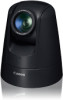
Thank you for purchasing Canon Network Camera VB-M40/VB-M40B (hereafter referred to as the
camera).
The only difference between VB-M40 and VB-M40B is the exterior color.
Be sure to read "Installation Guide" (this document) and "VB-M40 Operation Guide" (included in
the Setup CD-ROM) before use.
This "Installation Guide" explains the mounting method of the VB-M40 using the ceiling mount
cover (optional). Be sure to read the "Safety Precautions" section for correct use. After reading this
Installation Guide, keep it in a readily accessible location for future reference.
For the installation method of this camera using the indoor dome housing (optional), please read
the "DR40-C-VB/DR40-S-VB Installation Guide" bundled with the indoor dome housing.
The detailed procedures for using this camera are explained in the "VB-M40 Operation Guide".
Read these guides carefully before using the VB-M40 to ensure correct use.
* For the latest information (firmware and bundled software, instruction manuals, operating
environment, etc.) please check our website.
Caution
Request a professional installer for all camera installation work. Never
try to install VB-M40 yourself. Doing so may result in unforeseen
accidents such as dropping the camera or electric shock
.
Check Bundled Items
This product comes with the following items. If any item is missing, contact the dealer where you
purchased the product.
1. VB-M40/VB-M40B
4. VB-M40 Installation Guide (This document)
2. Power connector
5. Warranty card
3. Setup CD-ROM
6. Notice
Instruction Manuals
VB-M40 Installation Guide (This document)
This guide provides notes on the camera installation and explains the procedures to install the
camera using a ceiling mount cover (optional), as well as the main camera specifications.
VB-M40 Operation Guide (Included in the Setup CD-ROM)
This document explains the initial camera settings, Admin Tools settings, viewer operations
and troubleshooting, etc.
•
•
Options
Options can be bought separately as necessary. A ceiling mount cover or indoor dome housing is
necessary to install the camera on a ceiling.
Ceiling Mount Cover SS40-S-VB/SS40-B-VB
This dedicated optional item is used to install the camera on a ceiling. This installation guide
explains the mounting method.
The ceiling mount cover is available both in silver (SS40-S-VB) and black (SS40-B-VB), to match
the silver and black models of this camera.
Indoor Dome Housing DR40-C-VB/DR40-S-VB
This dedicated optional item lets you embed the camera into the ceiling, providing an installation
with a cleaner look. The dome is available in two colors: clear (DR40-C-VB) and smoked
(DR40-S-VB).
AC Adapter PA-V17
A dedicated AC adapter for this camera.
Symbols Indicating Safety Precautions
This Installation Guide uses the following marks to indicate important information the
user should know in order to use the product safely. Be sure to observe these items.
Warning
Inappropriate handling against the instruction accompanied by this
sign may result in death or serious injury. Be sure to observe these
warnings to ensure safety.
Caution
Inappropriate handling against the instruction accompanied by this
sign may result in injury. Be sure to observe these precautions to
ensure safety.
Caution
Inappropriate handling against the instruction accompanied by
this sign may result in property damage. Be sure to observe these
precautions.
Important
This symbol indicates important or restricted items. Be sure to read
this document.
Note
Contains reference information for operation or additional
explanations.
Safety Precautions
This section explains precautions that must be observed when using the camera. If they
are not observed, injury, death and/or property damage may occur. Read the following
information carefully and be sure to observe the precautions.
Installation Precautions
Warning
Do not install in the following places:
Places in strong direct sunlight, near heat-generating objects, or places subject to high
temperatures
Places near fire sources or flammable solvents (alcohol, thinner, etc.)
Humid or dusty places
Places subject to lamp black or steam
Places subject to sea air
Confined or enclosed places
Installing in such places may cause
fire or electric shock
.
•
•
•
•
•
•
Caution
For installation or inspection of this camera, consult or request the dealer where you
purchased the product.
This installation should be made by a qualified service person and should conform to all
local codes.
When installing on a ceiling, make sure the surface is capable of withstanding the
total weight of the ceiling mount cover and the camera, and is sufficiently reinforced if
necessary.
Periodically check the ceiling plates and fixing screws for rust and loose material to
prevent injuries and equipment damage due to falling items.
•
•
•
Do not install in unstable places, places subject to significant vibration or impact, or
places subject to salt damage or corrosive gas, as this may result in malfunction.
The camera cannot be installed on vertical surfaces such as walls.
Be sure to attach the safety wire when installing the camera.
Failure to do so may result in the camera falling or other accidents.
•
•
•
Do not touch the edges of metal parts with bare hands.
Do not insert your finger in the space between the parts and the ceiling.
Injury may result.
•
•
Caution
Do not carry the network camera by the camera head.
Do not turn the camera rotator by hand.
Do not install the camera on an unstable or inclined surface.
Malfunction may result.
•
•
•
Take care not to damage wiring or pipes in the room.
Damage to peripheral items may result.
•
Cautions on Use
Warning
If you discover defective conditions such as smoke, strange sounds, heat or strange
odors, immediately stop using the camera and contact your nearest dealer.
Continued use may cause fire or electric shock.
•
Do not disassemble or modify the camera.
Do not damage the connecting cord.
Do not spill water or other liquid inside the camera, spray the camera with water, or
otherwise make it wet.
Do not insert foreign objects into the camera.
Do not use flammable sprays near the camera.
Do not leave LAN cables, external power supplies or AC adapter (optional) power
connectors connected when the camera is not in use for long periods.
Do not use flammable solvents such as alcohol, paint thinner or benzine when cleaning
the camera.
Installing in such places may cause
fire or electric shock
.
•
•
•
•
•
•
•
Write the serial number and MAC address of the camera (printed on the seal at the bottom of
the camera) in the field below before storing this manual in a safe location.
Serial No.
_________________________________
MAC Address
_________________________________
©CANON INC. 2011
Printed in Taiwan
ENGLISH
CANON INC.
Notes on Power Supply
Warning
Only use the dedicated AC adapter PA-V17 (optional) for AC power.
Do not set any heavy objects on the power cable.
Do not pull, forcibly bend, scratch, or modify the power cable.
Do not cover or wrap the AC adapter (optional) with cloth or blankets.
Fire or electric shock may result.
Be sure to read the instruction manual for the PA-V17 (optional) before use.
•
•
•
•
Caution
Never touch the camera head during initialization. Initialization failure or malfunction
may result.
After turning off the power, wait for at least five seconds before turning the power on
again. If the power is turned on again too quickly, the camera may operate poorly.
•
•
External Dimensions
VB-M40/VB-M40B
130 mm (5.12 in)
132 mm (5.20 in)
124 mm
179 mm (7.05 in)
160 mm (6.30 in)
45 mm (1.77 in)
155 mm (6.10 in)
(
4.88 in)
* Even with the junction box
plate, the height of the
device is 160 mm (6.30 in)
Ceiling Mount Cover
45 mm
(1.77 in)
179 mm (
7.05 in)
128 mm (
5.04 in)
Junction Box Plate
85.7 mm
(3 3/8 in)
83.5 mm
(3 9/32 in)
46.0 mm
(1 13/16 in)
83.5 mm
(3 9/32 in)
85.7 mm
(3 3/8 in)
46.0 mm
(1 13/16 in)
4.5 mm
(
0.18 in)
Junction box fixing holes
Ceiling Plate
30.0 mm
(1.18 in)
94.0 mm (3.70 in)
144.0 mm (5.67 in)
20.0 mm
(0.79 in)
66.0 mm
(2.60 in)
4-
3.4 mm
(4-
0.14 in)
4-
3.4 mm
(4-
0.14 in)
4-
4.5mm
(4-
0.18 in)
Ceiling mount holes
Camera mounting holes
Junction box plate holes
Notes on Privacy and Publicity Rights Regarding the Use of
Video/Audio
When using the VB-M40 (for video or audio recording), it is the full responsibility of the user
to protect privacy and avoid any violation of publicity rights. Canon shall have no liability
whatsoever in this regard.
Reference
If identifiable structures or premises will be captured, be sure to gain approval of the building
management office before installing the camera.
Legal Notice
In some cases, camera monitoring may be prohibited by law or regulation, the details of which
differ by country or region. Before using the VB-M40, check the laws or regulations of the country
or region where the camera is used.
•
Main Specifications
Camera
Image Sensor
1/3 type CMOS (primary color filter)
Number of Effective Pixels
Approx. 1.3 million pixels
Scanning Method
Progressive
Lens
20x Optical (4x Digital) Zoom Lens with Autofocus
Focal Length
f=4.7 (W) – 94mm (T)
F-number
F1.6 (W) – F3.5 (T)
Viewing Angle
Horizontal: 55.4° (W) – 2.8° (T)/Vertical: 42.3° (W) – 2.2° (T)
Day/Night Switch
Auto or Manual. Auto switching between “Switching brightness” and “Response”.
Min. Subject Illumination
Day Mode (color) :
0.4 lux (F1.6, Shutter Speed 1/30 sec., when Smart Shade Control is off)
0.1 lux (F1.6, Shutter Speed 1/8 sec., when Smart Shade Control is off)
0.03 lux (F1.6, Shutter Speed 1/8 sec., when Smart Shade Control is on)
Night Mode (monochrome) :
0.01 lux (F1.6, Shutter Speed 1/30 sec., when Smart Shade Control is off)
0.002 lux (F1.6, Shutter Speed 1/8 sec., when Smart Shade Control is off)
0.001 lux (F1.6, Shutter Speed 1/8 sec., when Smart Shade Control is on)
Focus
Auto/One-shot AF/Manual/Fixed at infinity (for dome)
Shooting Distance
Day Mode: 0.3 m (12 in) –
∞
(W)/1.0 m (3.3 ft) –
∞
(T)
(from front of lens)
Night Mode: 1.0 m (3.3 ft) –
∞
(W)/1.5 m (4.9 ft) –
∞
(T)
Shutter Speed
1, 1/2, 1/4, 1/8, 1/15, 1/30, 1/60, 1/100, 1/120, 1/250, 1/500, 1/1000, 1/2000,
1/4000, 1/8000 sec.
Exposure
Auto/Flickerless/Shutter-Priority AE, Manual (Shutter Speed/Aperture/AGC Gain)
White Balance
Auto/Select Light Source (Warm Fluorescent, White Fluorescent, Daylight
Fluorescent, Mercury Lamp, Sodium Lamp, Halogen Lamp)/Manual/Lock (One-shot WB)
* Manual setting is available with RM-Lite
Metering Mode
3 options (Center-weighted/Average/Spot)
Exposure Compensation
7 levels
Smart Shade Control
7 levels (function for increasing the brightness of shaded subjects in an image with
sharp contrast of brightness and darkness)
Image Stabilizer
2 levels (Electronic)
Pan Angle Range
340° (±170°)
Tilt Angle Range
100º (Ceiling-mounted position: -90º – 10º)
Moving Rate
Pan: Max. 150º/sec, Tilt: Max. 150º/sec
Server
Video Compression Method
H.264, JPEG
Image Size
JPEG:
160 x 120, 320 x 240, 640 x 480, 1280 x 960
H.264:
320 x 240, 640 x 480, 1280 x 960
Image Quality
JPEG/H.264: 5 levels
Frame Rate *1
JPEG:
30 – 0.1 fps
H.264: 30/15/10 fps
Max. Frame Rate
Max. 30 fps (1280 x 960) *1
Simultaneous Client Access
JPEG:
Max. 30 Clients + 1 Admin Client
H.264: Max. 10 Clients
Audio Compression Method
G.711 μ-law (64 kbps)
Audio Communication Method
Full-duplex (two-way) - Echo cancellation function compliant
Audio Playback
available *2
Protocol
IPv4:
TCP/IP, UDP, HTTP, FTP, SNMP (MIB2), SMTP (Client), DHCP (Client),
DNS (Client), ARP, ICMP, POP3, NTP, SMTP authentication,
WV-HTTP (from Canon), ONVIF
IPv6:
TCP/IP, UDP, HTTP, FTP, SMTP (Client), DNS (Client), ICMPv6,
POP3, NTP, SMTP authentication, WV-HTTP (from Canon), ONVIF
On-Screen Display
available
Encrypted Communications
SSL/TLS, IPsec (Auto Key Exchange/Manual)
Camera Control
3 user levels available (Administrator/Authorized user/Guest user)
Up to 50 users’ user names and passwords can be set for Authorized users.
Preset Setting
Max. 20 positions. (Preset tour capable)
View Restriction
available
Privacy Mask
Number of registration: Max. 8 places, Number of mask colors: 1 (select from 9
colors)
Access Control
Access control (user name & password)/Host-based access control (IPv4, IPv6)
Intelligent Function
<Image>
Type of Detection: moving object detection, removed object detection,
abandoned object detection, and camera tampering detection
Field of Detection: Max. 15 places
<Volume>
Volume Detection
Event Trigger Type
External Device Input 1/2, Intelligent Function (Image), Intelligent Function (Volume),
Timer
Image Upload
FTP/HTTP/SMTP (e-mail)
Temporary storage memory in camera: Max.approx 4MB, Frame Rate: Max. 10 fps
Event Notification
HTTP/SMTP (e-mail)
Language
English/French/German/Italian/Spanish/Japanese
*1)
The frame rate may be reduced due to Viewer PC’s specs, the number of clients accessing at the same time, network
loads, type or movement of the subject, image quality setting or other reasons.
*2)
A separately-sold amplifier speaker is necessary for playing audio files.
“ONVIF” is trademarks of ONVIF Inc.
Interface
Network Terminal
LAN x 1 (RJ45, 100Base-TX (Auto/full-duplex/half-duplex))
Audio Input Terminal
Φ
3.5 mini-jack connector (monaural)
(common for LINE IN & MIC IN)
LINE IN/MIC IN can be switched in the setting page.
LINE IN x 1 (connect to an amplifier microphone) or MIC IN x 1 (connect to a
microphone w/o amplifier)
Audio Output Terminal
Φ
3.5 mini-jack connector (monaural)
(LINE OUT)
LINE OUT x 1 (connect to an amplifier speaker)
External device I/O Terminal
Input x 2
Output x 2
Memory Card
SD Memory Card, SDHC Memory Card Compatible. Max. 32 GB, Frame Rate: Max. 1fps
Others
Operating Environment
Temperature: -10 – 50°C (14 – 122°F)/Humidity: 5 – 85%RH (without condensation)
Power Supply
PoE: PoE power supply via LAN connector (IEEE802.3af compliant)
AC adapter: optional PA-V17 (AC 100 V)
External power source: AC 24 V/DC 12 V
Power Consumption
with PoE: Max. approx. 9.8 W/with AC adapter PA-V17: Max. approx. 12.5 W
Dimensions
Φ
132 x 155 mm (H) (
Φ
5.20 x 6.10 in (H)) (Camera only)
Weight
Approx. 1150 g (2.535 lb)
(Camera only)
AC Adapter (optional)
Model
PA-V17
Input
100 VAC 50/60 Hz
Output
13 VDC 1.8 A (MAX), temperature -10°C to 35°C humidity 20 to 85%RH
(non-condensing) When combined with the network camera
13 VDC 1.0 A (MAX), temperature -10°C to 45°C humidity 20 to 85%RH
(non-condensing)
Polarity
Black line side (-), white line side (+)
Dimensions
58 mm x 118 mm x 25 mm (2.28 in x 4.65 in x 0.98 in) (W x D x H) (excluding
projections)
Weight
Approx. 215 g (0.474 lb) (excluding cables)
Ceiling mount (optional)
Model
SS40-S-VB/SS40-B-VB
Type
Silver type/black type
Network camera-mounting
Temperature -10 to 50°C , humidity 5 to 85%RH (non-condensing)
environments
Dimensions
Φ
179 mm x 45 mm (7.05 in x 1.77 in) (H)
Weight
Approx. 378 g (0.833 lb) (ceiling mounting bracket, ceiling mount cover)
WARNING
To reduce a risk of fire or electric shock, do not expose this product
to rain or moisture.