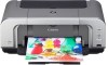
Canon iP4200 Service Manual
Canon iP4200 - PIXMA Photo Printer Manual
 |
UPC - 013803048438
View all Canon iP4200 manuals
Add to My Manuals
Save this manual to your list of manuals |
Canon iP4200 manual content summary:
- Canon iP4200 | Service Manual - Page 1
iP4200 SERVICE MANUAL Revision 0 QY8-13A9-000 COPYRIGHT©2005 CANON INC. CANON PIXMA iP4200 072005 XX 0.00-0 Scope This manual has been issued by Canon Inc., to provide the service technicians of this product with the information necessary for qualified persons to learn technical theory, installation - Canon iP4200 | Service Manual - Page 2
or changes made to the product. When changes are made to the contents of the manual, Canon will release technical information when necessary. When substantial changes are made to the contents of the manual, Canon will issue a revised edition. The following do not apply if they do not conform to the - Canon iP4200 | Service Manual - Page 3
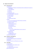
I. MANUAL OUTLINE This manual consists of the following three parts to provide information necessary to service the PIXMA iP4200: Part 1: Maintenance Information on maintenance and troubleshooting of the PIXMA iP4200 Part 2: Technical Reference New technology and technical information such as FAQ's - Canon iP4200 | Service Manual - Page 4
TECHNOLOGIES 2. CLEANING MODE AND AMOUNT OF INK PURGED 3. PRINT MODE 4. FAQ (Problems Specific to the iP4000 and Corrective Actions) Part 3: APPENDIX 1. BLOCK DIAGRAM 2. CONNECTOR LOCATION AND PIN LAYOUT 2-1. Logic Board Ass'y 2-2. Carriage Board (Print Head Connector) PIXMA iP4200 Specifications - Canon iP4200 | Service Manual - Page 5
Part 1 MAINTENANCE - Canon iP4200 | Service Manual - Page 6
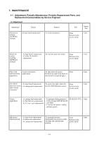
Service Engineer (1) Adjustment Adjustment Timing Purpose Tool Approx. time Destination settings (EEPROM settings) At logic board replacement To set the destination. None. Perform in the service mode. 1 min. Waste ink for the CD / DVD detection sensor. None. Perform in the service mode. - Canon iP4200 | Service Manual - Page 7
printer driver) print head cleaning. Ink tank replacement When an ink tank becomes empty. ("No ink error" via the computer, or ink tank LED flashing fast in red) Paper feed roller When necessary cleaning ----- To clean the paper feed rollers. ----Printer buttons 2 min. 2 min. CD / DVD print - Canon iP4200 | Service Manual - Page 8
(II) Years of use PIXMA iP4200: 5 years of use (2) Print head Print volume: 18,000 pages Black 1,500 character pattern Color A4, 7.5% duty per color pattern A4, photo, borderless printing 4 x 6, photo, borderless printing Postcard, photo, borderless printing (3) Ink tank (target value) 8,300 - Canon iP4200 | Service Manual - Page 9
Windows XP driver, using Windows XP Photo Printing Wizard. The print yield in the table above is an average value measured in continuous printing, using the ink tank immediately after it is unsealed, until the ink is out. Ink yield may vary depending on texts and photos printed, application software - Canon iP4200 | Service Manual - Page 10
by the LED, and warnings are displayed on the monitor of the computer connected to the printer. 2-1. Operator Call Errors (by Alarm LED Blinking in Orange) Alarm LED blinking in orange Error [Error code] 2 times No paper. (ASF) [1000] Solution Set the paper in the ASF, and press the Resume - Canon iP4200 | Service Manual - Page 11
the error, and enable printing. The service call error, indicating the waste ink absorber is full, is likely to occur soon. 9 times The connected digital camera or digital video camera does not support Camera Direct Printing. [2001] Remove the cable between the camera and the printer. 10 times - Canon iP4200 | Service Manual - Page 12
CD / DVD printing *2: Only for models not supporting CD / DVD printing 2-2. Service Call Errors (by Cyclic Blinking in Orange (Alarm LED) and Green (Power LED), or Alarm LED Lit in Orange) Cycles of blinking in orange (Alram LED) and green (Power LED) Error [Error code] 2 times Carriage error - Canon iP4200 | Service Manual - Page 13
times Other hardware error [6500] - Logic board ass'y (QM2-2670)*1 Continuous alternate blinking Alarm LED lit ROM error RAM error - Logic board ass'y (QM2-2670)*1 - Logic board ass'y (QM2-2670)*1 *1: Before replacement of the logic board ass'y, check the waste ink amount (by service test print - Canon iP4200 | Service Manual - Page 14
rise of the print head temperature If the print head temperature exceeds the specified limit, a Wait is inserted during printing, *1: If the warning is displayed, the carriage does not move to the ink tank replacement position when the access cover is opened. 2-4. Troubleshooting by Symptom - Canon iP4200 | Service Manual - Page 15
is faint, or white lines appear on printouts even after print head cleaning. Line(s) not included in the print data appears on printouts. Remove and re-install the print head, or replace the - ink tank, - print head*2, - purge unit, or - logic board ass'y*1. Paper gets smeared. A part of a line - Canon iP4200 | Service Manual - Page 16
the ink absorber kit (QY5-0146) when replacing the logic board ass'y. [See Section 3-3. Adjustment / Settings, (5) Service mode, for details.] *2: Replace the print head only after the print head deep cleaning is performed 2 times, and when the problem persists. To the top - Canon iP4200 | Service Manual - Page 17
/ Settings, (5) Service mode.] 2. Check the ink system function. [See 3.3. Adjustment / Settings, (5) Service mode.] - Service test print (Confirm CD / DVD and automatic print head alignment sensor correction, and ink system function.) 3. Perform the print head alignment in the user mode. - The - Canon iP4200 | Service Manual - Page 18
ink tube from being pinched when assembling the printer unit chassis into the bottom case unit. Since the tube conditions after assembly are not visible, perform the manual purging 3 or 4 times to confirm that no strange noise is heard. [See 3-2. Special Notes on Repair Servicing, (3) Printer - Canon iP4200 | Service Manual - Page 19
To the top 1-14 - Canon iP4200 | Service Manual - Page 20
3-2. Special Notes on Repair Servicing (1) External cover removal (I) Release the 2 hooks on the rear side of the printer (indicated by the blue circles). (II) in the slots on the left and right sides of the printer front shown in the figures below, release the hooks to remove the main case from the bottom - Canon iP4200 | Service Manual - Page 21
(2) Flexible cable and harness wiring, connection Be careful of wiring of the flexible cables and harness. Improper wiring or connection may cause breakage of a line, leading to ignition or emission of smoke. (I) Logic board ass'y wiring 1-16 - Canon iP4200 | Service Manual - Page 22
), fix the waste ink tube to the printer chassis and waste ink tube holder with tape (at 2 locations). If the tube is pinched and blocked, proper purging is prevented, resulting in ink leakage or strange noise. (No specific tape is specified. In the sample photo below, (1) is the orange tape, and - Canon iP4200 | Service Manual - Page 23
securing the waste ink tube with tape, be careful not to damage the tube in installing the printer unit chassis in the bottom case unit. With the units assembled, the tube conditions are not visible. To confirm the tube is free from damage, perform the manual purging 3 or 4 times, and confirm that - Canon iP4200 | Service Manual - Page 24
stretched (in the direction indicated by the blue arrow in the figure below). 2) After replacement, be sure to perform the service test print, and confirm that no strange noise or faulty print operation (due to dislocation of the belt or gear, or out-of-phase motor, etc.) occurs. Note: The red - Canon iP4200 | Service Manual - Page 25
1-20 - Canon iP4200 | Service Manual - Page 26
2) CL base / CL gear 3) PR shaft / LF roller bushing To the top 1-21 - Canon iP4200 | Service Manual - Page 27
.] (4) User mode Function Print head manual cleaning Print head deep cleaning Paper feed roller cleaning Procedures - Cleaning both black and color: See "Standalone printer operation" below. - Cleaning black or color separately, or both black and color: Perform from the printer driver Maintenance - Canon iP4200 | Service Manual - Page 28
ridge facing down. 7 times 8 times or more The widest head-to-paper distance setting Unspecified (5) Service mode Function Service test print - Model name - Destination - ROM version - USB serial number - Waste ink amount - CD / DVD sensor correction value - Ink system function check result - Canon iP4200 | Service Manual - Page 29
) Print head deep cleaning (Cleaning of both black and color) 7 times Orange (Alarm) Reserved 8 times Green (Power) CD / DVD check pattern print Not used in servicing. 9 times Orange (Alarm) CD / DVD print position correction (horizontal: X direction) Not used in servicing. 10 times Green - Canon iP4200 | Service Manual - Page 30
6 times Green (Power) Asia Supported 7 times Orange (Alarm) China Supported 8 times Green (Power) Taiwan Supported 9 times Orange (Alarm) Return to the menu selection Note: After setting the destination, confirm the model name and destination in service test print or EEPROM information print. - Canon iP4200 | Service Manual - Page 31
iP4200: Model name JPN: Destination Vx.xx: ROM version USB (xxxxxx): USB serial number FA = xx xx xx: Reserved for plant use D = xxx.x: Waste ink amount (%) CDR (+xxxxx, +yyyyy): CD / DVD sensor position correction value AB (K = OK Y = ...): Ink system check result On the service - Canon iP4200 | Service Manual - Page 32
(2) EEPROM information print Print sample: iP4200 JPN V1.04 IF(USB2=1) D=004.5 ST=2005/05/27-18:30 ER(ER0=1000 ER1=5100) LPT=2005/06/09-09:09 PC(M=002 R= - Canon iP4200 | Service Manual - Page 33
count/ink tank replacement) 9. Cleaning time (BK/CL) 10. Print head replacement count 11. Ink tank replacement count (PBK/BK/Y/M/C) 12. Ink status (PBK/BK/Y/M/C) 13. Power-on count (soft) 14. Automatic print head alignment by user 15. Manual print head alignment by user 16. User print head alignment - Canon iP4200 | Service Manual - Page 34
the procedures for transporting the printer for returning after repair, etc. 1) In the service mode, press the Power button to finish the mode, and confirm that the paper lifting plate of the sheet feeder unit is raised. 2) Keep the print head and ink tanks installed in the carriage. [See Caution - Canon iP4200 | Service Manual - Page 35
Part 2 TECHNICAL REFERENCE - Canon iP4200 | Service Manual - Page 36
the FINE technologies, 1 pl of ultra-fine ink droplet is adopted. The iP4200 provides excellent super-photo print quality without graininess at the maximum resolution of 9,600 dpi x 2,400 dpi*1, which is equal to that of a 6-color printer. *1: Printing at the minimum distance of 1/9600 inch between - Canon iP4200 | Service Manual - Page 37
. - Manual cleaning / deep cleaning: Performed manually. Black: Pigment-based black Color: Dye-based black, cyan, magenta, yellow Condition On arrival of the printer Details First to third cleaning after shipped from the plant. Amount of ink used Est. required time (g) (sec - Canon iP4200 | Service Manual - Page 38
) When an ink tank is replaced (without the 0.30 (Black) print head removal or re-installation) 1.00 (Color) Manual cleaning (Black/Color/All at the same time) - Via the operation panel (All at the same 0.14 (Black) time only) 0.50 (Color) - Via the printer driver (Selectable from Black - Canon iP4200 | Service Manual - Page 39
3. PRINT MODE 3-1. Resolution (1) Normal color printing (2) Grayscale printing 2-4 - Canon iP4200 | Service Manual - Page 40
(3) Borderless printing (4) Duplex printing (5) Camera Direct printing To the top 2-5 - Canon iP4200 | Service Manual - Page 41
printing, printing is plate cleaning smeared. paper (lines or streaks parallel to the paper feed direction) of small sized paper (such as 4 x 6), when a larger sized paper (such performed to the size slightly larger than the paper size, and ink off the (from the - The back side printer driver - Canon iP4200 | Service Manual - Page 42
automatic of paper gets duplex printing, smeared. and manually print - Even after each side of paper. Bottom plate cleaning was Cleaning by user: performed, 1. Perform Bottom plate cleaning (from the printer driver) up to 3 times*1. and the platen ribs were cleaned with cotton swab, paper - Canon iP4200 | Service Manual - Page 43
the paper). Soiling on paper The printer has been Due to ink mist Clean the ASF sub- used for a long attached to the ASF rollers (see *3 for period of time with sub-pick-up rollers. details.) the ASF cover If printing is done closed before from the cassette printing is with the ASF cover - Canon iP4200 | Service Manual - Page 44
*3: How to prepare and set the ASF sub-roller cleaning sheet: 1) Fold a sheet of plain paper lengthwise in half. 2-9 - Canon iP4200 | Service Manual - Page 45
cover edge to hook the paper to the ASF cover, as shown below. 4) Press and hold the Resume/Cancel button until the Power LED blinks 3 times, then release the button to perform the paper feed roller cleaning. See "Stand alone printer operation," for details. 2-10 - Canon iP4200 | Service Manual - Page 46
) B: The symptom may occur under certain conditions, but likeliness is assumed very low in practical usage. C: The symptom is unlikely to be recognized by the user, and no practical issues are assumed. To the top 2-11 - Canon iP4200 | Service Manual - Page 47
Part 3 APPENDIX - Canon iP4200 | Service Manual - Page 48
1. BLOCK DIAGRAM 1-1. PIXMA iP4200 3-1 To the top - Canon iP4200 | Service Manual - Page 49
2. CONNECTOR LOCATION AND PIN LAYOUT 2-1. Logic Board Ass'y CN101 Not used CN201 (Print head 1/2 [Carriage unit]) No. Signal name 1 AB_PWR 2 AB_DATA 3 AB_PWR 4 AB_CLK 5 LOGIC_GND 6 H_D3 7 H_D0 8 H_D1 9 H_D5 10 H_ENB0 11 LOGIC_GND 12 DIA0 13 LOGIC_GND 14 H_D2 15 H_D4 16 H_ENB3 17 - Canon iP4200 | Service Manual - Page 50
GND CN202 (Print head 2/2 [Carriage unit]) No. Signal name 1 to 3 H_GND 4 to 6 HVH_24V 7 to 10 H_GND 11to 12 HVH_16V 13 to HVH_24V 16 17 LOGIC_GND 18 HVDD_3.3V 19 LOGIC_GND 20 HVDD_3.3V Function Head GND Head drive power supply 24V Head GND Head drive power supply 16V Head drive power supply - Canon iP4200 | Service Manual - Page 51
CN301 (AC adapter) No. Signal name 1 VH2 2 H2_GND 3 VH1 4 H1_GND 5 VM 6 M_GND 7 PW_CONT Function Head power supply Head GND Head power supply Head GND Motor power supply Motor GND Power supply control signal CN302 (USB I/F) No. Signal name 1 SNS_USB 2 D3 D+ 4 GND 5 to 9 GND Function USB: VBUS - Canon iP4200 | Service Manual - Page 52
10 AB_POW 11 DOOR 12 AB_SNS 13 INK_CDRS_PWM 14 SNS_INKS Function Resume key switch Bin 1 LED display Resume LED display Bin 2 LED display Power key switch Bin switch Power LED display GND Front cover sensor Power supply for AB Door sensor AB sensor CD-R LED control signal Ink sensor - Canon iP4200 | Service Manual - Page 53
CN501 (Motor multi harness) No. Signal name 1 CR_M 2 CR_MN 3 PF_MN 4 PF_M 5 AP_M 6 AP_MN 7 LF_M 8 LF_MN CR motor + CR motor PF motor PF motor + AP motor + AP motor LF motor + LF motor - Function Input / Output OUT OUT OUT OUT OUT OUT OUT OUT - Canon iP4200 | Service Manual - Page 54
2-2. Carriage Board (Print Head Connector) No. Signal name 1, 2 A_GNDH 3 HD2_C1 4 HD8_Y1 5 VSS 6 HD6_PBK1 7, 8 B_GNDH 9 HD3_SC1 10 HD5_SM1 11 HD4_M1 12 HENB1 13 HD10_SM2 14 VSS 15 HD11_M2 16 DIK 17 HD0_K1 18 HENB0 19 HENB3 20 HLAT 21 HD12_SC2 22 HD7_PBK2 - Canon iP4200 | Service Manual - Page 55
37 ROM_DIO (I) 38 DIA1 39 VHT 40 B_VH_24V Head data C2 Head drive power supply 16V Head drive power supply 24V Head logic power supply 3.3V Head EEPROM serial clock signal Head EEPROM data signal Diode sensor anode 1 Head drive power supply 24V Head drive power supply 24V - Canon iP4200 | Service Manual - Page 56
10.7ppm Bi-directional, uni-directional Max. 203.2mm (216mm in borderless printing) Interface USB 2.0 Hi-Speed ASF stacking capacity Plain paper: Max. 13mm (Approx. 150 sheets of 64g/m2 paper) Paper weight 64 to 105g/m2 Detection functions Access cover open, Presence of print head / ink - Canon iP4200 | Service Manual - Page 57
black, Dye-based black, cyan, magenta, yellow PGI-5BK (pigment-based), CLI-8BK/C/M/Y (dye-based) Print head, approx. 56g As a service part (not including ink tanks) QY6-0059-000 Model name and destination PIXUS iP4200 PIXMA iP4200 Japan Other than Japan BCI- PGI9BK 5BK
-
 1
1 -
 2
2 -
 3
3 -
 4
4 -
 5
5 -
 6
6 -
 7
7 -
8
-
9
-
10
-
11
-
12
-
13
-
14
-
15
-
16
-
17
-
18
-
19
-
20
-
21
-
22
-
23
-
24
-
25
-
26
-
27
-
28
-
29
-
30
-
31
-
32
-
33
-
34
-
35
-
36
-
37
-
38
-
39
-
40
-
41
-
42
-
43
-
44
-
45
-
46
-
47
-
48
-
49
-
50
-
51
-
52
-
53
-
54
-
55
-
56
-
57
 |
 |

PIXMA iP4200
SERVICE MANUAL
Revision 0
QY8-13A9-000
COPYRIGHT©2005 CANON INC. CANON PIXMA iP4200 072005 XX 0.00-0
Scope
This manual has been issued by Canon Inc., to provide the service technicians of this product with the information
necessary for qualified persons to learn technical theory, installation, maintenance, and repair of products. The manual
covers information applicable in all regions where the product is sold. For this reason, it may contain information that is
not applicable to your region.
Revision