Cisco 12406 Chassis Replacement Instructions
Cisco 12406 Manual
 |
UPC - 882658103230
View all Cisco 12406 manuals
Add to My Manuals
Save this manual to your list of manuals |
Cisco 12406 manual content summary:
- Cisco 12406 | Chassis Replacement Instructions - Page 1
Cisco 12006 and Cisco 12406 Router Chassis Replacement Instructions Product Number: GSR6/120= Document Order Number: DOC-7816109= This publication explains how to remove and install the Cisco 12006 or Cisco 12406 Router chassis. It includes referrals to other Cisco publications that include the - Cisco 12406 | Chassis Replacement Instructions - Page 2
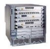
such as the power supplies, line cards, route processors (RPs), switch fabric card set, alarm cards, power distribution unit, and blower module. (See Figure 1.) The same chassis is used for both DC-powered and AC-powered Cisco 12006 or Cisco 12406 Routers. Figure 1 Replacement Chassis (Front View - Cisco 12406 | Chassis Replacement Instructions - Page 3
chassis. Figure 2 Cisco 12006 or Cisco 12406 Router (Front View) 12 8 3 101344 7 CISCO 12000 GIGABIT SWITCH SERIES ROUTER 6 EJECT SSLLOOTT--01 RESET AUX CONSOLE COLL RX LINK TX RJ-45 MII GIGABIT ROUTE PROCESSOR 5 1 Line cards 2 RP 3 Blower module 4 SFCs 4 5 Alarm cards 6 Power - Cisco 12406 | Chassis Replacement Instructions - Page 4
The following Cisco publications contain additional information: • Cisco 12006 and Cisco 12406 Router Installation and Configuration Guide • Regulatory Compliance and Safety Information for the Cisco 12000 Series Router Cisco 12006 and Cisco 12406 Router Chassis Replacement Instructions 4 78-16109 - Cisco 12406 | Chassis Replacement Instructions - Page 5
makes the equipment unsafe. • Never install equipment that appears damaged. • Carefully examine your work area for possible hazards such as moist floors, ungrounded power extension cables, and missing safety grounds. 78-16109-01 Cisco 12006 and Cisco 12406 Router Chassis Replacement Instructions 5 - Cisco 12406 | Chassis Replacement Instructions - Page 6
of the carrier to guide it straight out of the slot. • Handle line cards, clock and scheduler cards, switch fabric cards, or an RP by the metal card carrier edges only; avoid touching the board or any connector pins. Cisco 12006 and Cisco 12406 Router Chassis Replacement Instructions 6 78-16109-01 - Cisco 12406 | Chassis Replacement Instructions - Page 7
chassis to the replacement chassis. • The replacement chassis (with all the components now installed in it) is inserted into the same equipment rack or on a stable flat surface in place of the defective chassis. 78-16109-01 Cisco 12006 and Cisco 12406 Router Chassis Replacement Instructions - Cisco 12406 | Chassis Replacement Instructions - Page 8
and grounding cable and connector requirements, refer to Chapter 2 of the Cisco 12006 and Cisco 12406 Router Installation and Configuration Guide. Removing and Installing the Chassis Procedures for removing and installing the chassis are described in the following sections: • Preparing the Defective - Cisco 12406 | Chassis Replacement Instructions - Page 9
PDU, and facility DC power connects to the PDU through source DC power cable leads clamped into two DC connector blocks. (See Figure 8 and Figure 9.) Figure 6 AC-Powered Router-Rear View, Blower Module Removed 57676 78-16109-01 Cisco 12006 and Cisco 12406 Router Chassis Replacement Instructions 9 - Cisco 12406 | Chassis Replacement Instructions - Page 10
Figure 7 1 AC Power Distribution Unit 4 3 5 6 1 Captive screw (four) 2 AC power cord receptacle A 3 AC power cord receptacle B 2 4 AC power distribution unit 5 Guide pin 6 Blower module connector 57650 Cisco 12006 and Cisco 12406 Router Chassis Replacement Instructions 10 78-16109-01 - Cisco 12406 | Chassis Replacement Instructions - Page 11
DC source power should be connected to the terminal block: the negative lead is connected to the top port, the positive lead is connected to the middle port, and the ground lead is connected to the bottom port. 78-16109-01 Cisco 12006 and Cisco 12406 Router Chassis Replacement Instructions - Cisco 12406 | Chassis Replacement Instructions - Page 12
module LEDs are off • All alarm card LEDs are off • All RP and line card LEDs are off Caution In a noisy environment, place your hand in front of the exhaust vents at the rear of the chassis to verify that the blowers are off. Cisco 12006 and Cisco 12406 Router Chassis Replacement Instructions 12 - Cisco 12406 | Chassis Replacement Instructions - Page 13
RP and Line Cards, page 16 • Transferring the Clock and Scheduler Cards, Switch Fabric Cards, and Alarm Cards, page 18 • Removing the Blower Module, page 23 • Transferring the Power Distribution Unit, page 24 78-16109-01 Cisco 12006 and Cisco 12406 Router Chassis Replacement Instructions 13 - Cisco 12406 | Chassis Replacement Instructions - Page 14
free hand to support the power module while you slide it completely out of the bay. Move the power module away from the chassis and set it aside. Figure 10 Removing a Power Module (AC-Input Power Supply Shown) 84372 Cisco 12006 and Cisco 12406 Router Chassis Replacement Instructions 14 78-16109 - Cisco 12406 | Chassis Replacement Instructions - Page 15
the bay and secure it by closing the ejector levers. Step 6 Use a flat-blade screwdriver to tighten the two ejector lever captive screws. Figure 11 Installing a Power Module (AC-Input Power Supply Shown) 84373 78-16109-01 Cisco 12006 and Cisco 12406 Router Chassis Replacement Instructions 15 - Cisco 12406 | Chassis Replacement Instructions - Page 16
0 ACTIVCEARRRIEXRCELL Velcro strap OC-12/STM-4 POS Step 4 After all the interface cables are disconnected, loosen the two captive screws on the cable-management bracket and pull the bracket away from the card. Cisco 12006 and Cisco 12406 Router Chassis Replacement Instructions 16 78-16109-01 - Cisco 12406 | Chassis Replacement Instructions - Page 17
gasket contacts, because a damaged card carrier gasket can reduce EMI performance. Caution Handle the RP or line cards by the metal card carrier edges only; avoid touching the board itself or any connector pins. 78-16109-01 Cisco 12006 and Cisco 12406 Router Chassis Replacement Instructions 17 - Cisco 12406 | Chassis Replacement Instructions - Page 18
not populated with a line card, a blank line card must be installed to avoid overheating and to ensure electromagnetic compliance (EMC). Transferring the Clock and Scheduler Cards, Switch Fabric Cards, and Alarm Cards Cisco 12006 and Cisco 12406 Routers are equipped with chassis slots for two CSCs - Cisco 12406 | Chassis Replacement Instructions - Page 19
from the card faceplate. c. Slide the CSC halfway out of the slot, then stop. d. Touching only the metal card carrier, use your free hand to support the bottom of the CSC as you slide the card out of the slot. 78-16109-01 Cisco 12006 and Cisco 12406 Router Chassis Replacement Instructions 19 - Cisco 12406 | Chassis Replacement Instructions - Page 20
a Switch Fabric Card CISCO 12000 GIGABIT SWITCH SERIES ROUTER EJECT SSLLOOTT--01 RESET AUX CONSOLE COLL RX LINK TX RJ-45 MII GIGABIT ROUTE PROCESSOR 101410 1 2 3 1 SFC 2 Captive screw (2) 3 Ejector lever (2) -- Cisco 12006 and Cisco 12406 Router Chassis Replacement Instructions 20 - Cisco 12406 | Chassis Replacement Instructions - Page 21
cards from the defective chassis to the replacement chassis, remove each alarm card and immediately install the alarm card in the same slot of the replacement chassis as described in the procedure in this section. 78-16109-01 Cisco 12006 and Cisco 12406 Router Chassis Replacement Instructions 21 - Cisco 12406 | Chassis Replacement Instructions - Page 22
and Installing an Alarm Card CISCO 12000 GIGABIT SWITCH SERIES ROUTER EJECT slot. Install the alarm card in the replacement chassis: a. Touching only the handle, use your free hand to support the bottom chassis. Cisco 12006 and Cisco 12406 Router Chassis Replacement Instructions 22 78-16109-01 - Cisco 12406 | Chassis Replacement Instructions - Page 23
both hands, pull the blower module away from the chassis and the guide pins. Grasp the blower module handle with two hands, lift the module away from the rear of the chassis, and set the blower module safely aside. 78-16109-01 Cisco 12006 and Cisco 12406 Router Chassis Replacement Instructions 23 - Cisco 12406 | Chassis Replacement Instructions - Page 24
and Cisco 12406 Routers are equipped with one PDU, which mounts on the rear of the chassis, near the bottom, behind the blower module. (See Figure 6.) With the exception of the power wiring connectors, the DC PDU and the AC PDU are similar physical packages for purposes removing and installing the - Cisco 12406 | Chassis Replacement Instructions - Page 25
chassis. (See Figure 5.) Removing the Defective Chassis from a Tabletop or Flat Surface Site To remove the defective chassis from a tabletop or flat surface installation the chassis to the equipment rack rails. 78-16109-01 Cisco 12006 and Cisco 12406 Router Chassis Replacement Instructions 25 - Cisco 12406 | Chassis Replacement Instructions - Page 26
as outlined in Statement 5 of the Regulatory Compliance and Safety Information for Cisco 12000 Series Routers publication (Document Number 78-4347-xx) while lifting the chassis and setting it safely aside. Cisco 12006 and Cisco 12406 Router Chassis Replacement Instructions 26 78-16109-01 - Cisco 12406 | Chassis Replacement Instructions - Page 27
: Step 1 Step 2 Move the router as close to the installation location as possible. With one person positioned at the front of the chassis and one at the rear, lift the router and position it on the flat surface. 78-16109-01 Cisco 12006 and Cisco 12406 Router Chassis Replacement Instructions 27 - Cisco 12406 | Chassis Replacement Instructions - Page 28
system is to be connected to the supplemental bonding and grounding receptacle on the Cisco 12006 and Cisco 12406 Router chassis, connect the supplemental bonding and grounding cable to the chassis. (See Figure 5.) Cisco 12006 and Cisco 12406 Router Chassis Replacement Instructions 28 78-16109-01 - Cisco 12406 | Chassis Replacement Instructions - Page 29
the Router This section contains the following procedures: • Reconnecting Power to a Router Equipped with the AC Power Distribution Unit • Reconnecting Power to a Router Equipped with the DC Power Distribution Unit 78-16109-01 Cisco 12006 and Cisco 12406 Router Chassis Replacement Instructions 29 - Cisco 12406 | Chassis Replacement Instructions - Page 30
are tight. Installing the Blower Module After the chassis power has been reconnected to the PDU, install the blower module on the replacement chassis. To install the blower module, see Figure 17 and follow these steps: Cisco 12006 and Cisco 12406 Router Chassis Replacement Instructions 30 78 - Cisco 12406 | Chassis Replacement Instructions - Page 31
air flow through the chassis and proper compliance with electromagnetic compatibility (EMC) regulations. • Power modules are fully inserted in their bays and their ejector levers are all completely closed and secured. 78-16109-01 Cisco 12006 and Cisco 12406 Router Chassis Replacement Instructions - Cisco 12406 | Chassis Replacement Instructions - Page 32
that AC power source is present and is within specified limits. The power supply fan should also be on. - Green LED labeled DC-Power supply is operating normally in a powered-on condition. • For a router equipped with DC-input PEMs: - Green LED labeled INPUT OK-When the power module is fully - Cisco 12406 | Chassis Replacement Instructions - Page 33
power modules do not power up, or if the system or any interfaces do not initialize properly, see Chapter 4, "Troubleshooting the Installation" in the Cisco 12006 and Cisco 12406 Router Installation and Configuration Guide. If you are still unable to resolve the problem, contact your Cisco service - Cisco 12406 | Chassis Replacement Instructions - Page 34
side-to-side over the top of the shipping container to secure it to the shipping pallet base. The chassis is now repackaged and ready to be transported. Use a forklift or pallet jack to move the repackaged chassis. Cisco 12006 and Cisco 12406 Router Chassis Replacement Instructions 34 78-16109-01 - Cisco 12406 | Chassis Replacement Instructions - Page 35
SSLLOOTT--01 RESET AUX CONSOLE COLL RX LINK TX RJ-45 MII GIGABIT ROUTE PROCESSOR 3 101113 1 Pallet base 2 Router 3 Hold-down brackets with bolts 4 Plastic bag 5 Accessory kit tray 6 Outer shipping container 78-16109-01 Cisco 12006 and Cisco 12406 Router Chassis Replacement Instructions 35 - Cisco 12406 | Chassis Replacement Instructions - Page 36
instruction manual, may cause harmful interference to radio communications. Operation of this equipment in a residential area is likely to cause harmful interference, in which case users will be required to correct the interference at their own expense. Cisco 12006 and Cisco 12406 Router Chassis - Cisco 12406 | Chassis Replacement Instructions - Page 37
Information Technology Equipment (VCCI). If this equipment is used in a domestic environment, radio disturbance may arise. When such trouble occurs, the user may be required to take corrective actions. Statement 191 78-16109-01 Cisco 12006 and Cisco 12406 Router Chassis Replacement Instructions 37 - Cisco 12406 | Chassis Replacement Instructions - Page 38
conditions of installation and protection Cisco provides several ways to obtain documentation, technical assistance, and other technical resources. These sections explain how to obtain technical information from Cisco Systems. Cisco 12006 and Cisco 12406 Router Chassis Replacement Instructions - Cisco 12406 | Chassis Replacement Instructions - Page 39
). Documentation Feedback You can submit comments electronically on Cisco.com. On the Cisco Documentation home page, click Feedback at the top of the page. You can send your comments in e-mail to [email protected]. 78-16109-01 Cisco 12006 and Cisco 12406 Router Chassis Replacement Instructions 39 - Cisco 12406 | Chassis Replacement Instructions - Page 40
Pacific: +61 2 8446 7411 (Australia: 1 800 805 227) EMEA: +32 2 704 55 55 USA: 1 800 553-2447 For a complete listing of Cisco TAC contacts, go to this URL: http://www.cisco.com/warp/public/687/Directory/DirTAC.shtml Cisco 12006 and Cisco 12406 Router Chassis Replacement Instructions 40 78-16109-01 - Cisco 12406 | Chassis Replacement Instructions - Page 41
.html • Training-Cisco offers world-class networking training. Current offerings in network training are listed at this URL: http://www.cisco.com/en/US/learning/le31/learning_recommended_training_list.html 78-16109-01 Cisco 12006 and Cisco 12406 Router Chassis Replacement Instructions 41 - Cisco 12406 | Chassis Replacement Instructions - Page 42
Cisco 12006 and Cisco 12406 Router Chassis Replacement Instructions 42 78-16109-01 - Cisco 12406 | Chassis Replacement Instructions - Page 43
be used in conjunction with the Cisco 12006 and Cisco 12406 Router Installation and Configuration Guide. CCVP, the Cisco logo, and the Cisco Square Bridge logo are trademarks of Cisco Systems, Inc.; Changing the Way We Work, Live, Play, and Learn is a service mark of Cisco Systems, Inc.; and Access - Cisco 12406 | Chassis Replacement Instructions - Page 44
Cisco 12006 and Cisco 12406 Router Chassis Replacement Instructions 44 78-16109-01
-
 1
1 -
 2
2 -
 3
3 -
 4
4 -
 5
5 -
 6
6 -
 7
7 -
8
-
9
-
10
-
11
-
12
-
13
-
14
-
15
-
16
-
17
-
18
-
19
-
20
-
21
-
22
-
23
-
24
-
25
-
26
-
27
-
28
-
29
-
30
-
31
-
32
-
33
-
34
-
35
-
36
-
37
-
38
-
39
-
40
-
41
-
42
-
43
-
44
 |
 |

Corporate Headquarters:
Copyright © 2004 Cisco Systems, Inc. All rights reserved.
Cisco Systems, Inc., 170 West Tasman Drive, San Jose, CA 95134-1706
USA
Cisco 12006 and Cisco 12406 Router
Chassis Replacement Instructions
Product Number: GSR6/120=
Document Order Number: DOC-7816109=
This publication explains how to remove and install the Cisco 12006 or Cisco 12406 Router chassis. It
includes referrals to other Cisco publications that include the information required to complete these
procedures.
These two router models are differentiated by the switching capacity of the switch fabric installed in the
router:
•
Cisco 12006 Router—2.5-Gbps switch fabric
•
Cisco 12406 Router—10-Gbps switch fabric
Other than the switch fabric, these routers are identical in most respects. Any differences between the
models are described in the appropriate locations. Unless otherwise noted, all information in this
publication applies to both router models.
Contents
•
Replacement Chassis Overview, page 2
•
Preparing for Installation, page 4
•
Before You Begin, page 7
•
Removing and Installing the Chassis, page 8
•
Restarting the Router, page 31
•
Packaging the Replaced Chassis for Shipment, page 33
•
Regulatory, Compliance, and Safety Information, page 36
•
Obtaining Documentation, page 38
•
Obtaining Technical Assistance, page 40
•
Obtaining Additional Publications and Information, page 41