Cisco 2431 Hardware Installation Guide
Cisco 2431 - IAD Router Manual
 |
UPC - 746320759852
View all Cisco 2431 manuals
Add to My Manuals
Save this manual to your list of manuals |
Cisco 2431 manual content summary:
- Cisco 2431 | Hardware Installation Guide - Page 1
Cisco ME 2400 Ethernet Access Switch Hardware Installation Guide November 2005 Corporate Headquarters Cisco Systems, Inc. 170 West Tasman Drive San Jose, CA 95134-1706 USA http://www.cisco.com Tel: 408 526-4000 800 553-NETS (6387) Fax: 408 526-4100 Text Part Number: OL-7678-01 - Cisco 2431 | Hardware Installation Guide - Page 2
in this document or Website are the property of their respective owners. The use of the word partner does not imply a partnership relationship between Cisco and any other company. (0502R) Cisco ME 2400 Ethernet Access Switch Hardware Installation Guide © 2005 Cisco Systems, Inc. All rights reserved. - Cisco 2431 | Hardware Installation Guide - Page 3
up the Switch 1-1 Features 1-1 Front Panel Description 1-2 Front Panel Descriptions 1-3 10/100 Ports 1-3 SFP Module Slots 1-4 SFP Modules 1-4 SFP Module Patch Cable 1-5 LEDs 1-5 System LED 1-5 Port LEDs 1-6 CONTENTS OL-7678-01 Cisco ME 2400 Ethernet Access Switch Hardware Installation Guide iii - Cisco 2431 | Hardware Installation Guide - Page 4
10/100 Ports 2-22 Connecting to SFP Modules 2-23 Connecting to Fiber-Optic SFP Modules 2-23 Connecting to 1000BASE-T SFP Modules 2-24 Where to Go Next 2-25 Troubleshooting 3-1 Understanding POST Results 3-1 Diagnosing Problems 3-1 Cisco ME 2400 Ethernet Access Switch Hardware Installation Guide iv - Cisco 2431 | Hardware Installation Guide - Page 5
to the Console Port D-3 Starting the Terminal-Emulation Software D-4 Connecting to a Power Source D-5 Entering the Initial Configuration Information D-5 IP Settings D-5 Completing the Setup Program D-6 Contents OL-7678-01 Cisco ME 2400 Ethernet Access Switch Hardware Installation Guide v - Cisco 2431 | Hardware Installation Guide - Page 6
Contents Cisco ME 2400 Ethernet Access Switch Hardware Installation Guide vi OL-7678-01 - Cisco 2431 | Hardware Installation Guide - Page 7
some of the problems that might arise when installing the switch. Appendix A, "Technical Specifications," lists the physical and environmental specifications for the switches and the regulatory agency approvals. OL-7678-01 Cisco ME 2400 Ethernet Access Switch Hardware Installation Guide vii - Cisco 2431 | Hardware Installation Guide - Page 8
number provided at the end of each warning to locate its translation in the translated safety warnings that accompanied this device. Statement 1071 SAVE THESE INSTRUCTIONS , wilt raadplegen. BEWAAR DEZE INSTRUCTIES Cisco ME 2400 Ethernet Access Switch Hardware Installation Guide viii OL-7678-01 - Cisco 2431 | Hardware Installation Guide - Page 9
appareil, référez-vous au numéro de l'instruction situé à la fin de chaque avertissement. ällen vertraut. Suchen Sie mit der am Ende jeder Warnung angegebenen Anweisungsnummer nach der jeweiligen Ü INSTRUKSJONENE OL-7678-01 Cisco ME 2400 Ethernet Access Switch Hardware Installation Guide ix - Cisco 2431 | Hardware Installation Guide - Page 10
änd det nummer som finns i slutet av varje varning för att hitta dess översättning i de översatta säkerhetsvarningar som medföljer denna anordning. SPARA DESSA ANVISNINGAR Cisco ME 2400 Ethernet Access Switch Hardware Installation Guide x OL-7678-01 - Cisco 2431 | Hardware Installation Guide - Page 11
. Brug erklæringsnummeret efter hver advarsel for at finde oversættelsen i de oversatte advarsler, der fulgte med denne enhed. GEM DISSE ANVISNINGER OL-7678-01 Cisco ME 2400 Ethernet Access Switch Hardware Installation Guide xi - Cisco 2431 | Hardware Installation Guide - Page 12
Conventions Preface Cisco ME 2400 Ethernet Access Switch Hardware Installation Guide xii OL-7678-01 - Cisco 2431 | Hardware Installation Guide - Page 13
for the latest information. • Release Notes for the Cisco ME 2400 Ethernet Access Switch (not orderable but available on Cisco.com) • Cisco ME 2400 Ethernet Access Switch Software Configuration Guide (order number DOC-78-17059=). This guide provides a product overview and detailed descriptions and - Cisco 2431 | Hardware Installation Guide - Page 14
• Cisco ME 2400 Ethernet Access Switch Command Reference (order number DOC-78-78-17061=). This reference provides detailed descriptions of the Cisco IOS commands specifically created or modified for the switch. • Cisco Metro Ethernet 2400 Ethernet Access Switch System Message Guide (order number DOC - Cisco 2431 | Hardware Installation Guide - Page 15
as they are updated in real time, you can access a Product Security Incident Response Team Really Simple Syndication (PSIRT RSS) feed from this URL: http://www.cisco.com/en/US/products/products_psirt_rss_feed.html OL-7678-01 Cisco ME 2400 Ethernet Access Switch Hardware Installation Guide xv - Cisco 2431 | Hardware Installation Guide - Page 16
Support & Documentation website requires a Cisco.com user ID and password. If you have a valid service contract but do not have a user ID or password, you can register at this URL: http://tools.cisco.com/RPF/register/register.do Cisco ME 2400 Ethernet Access Switch Hardware Installation Guide - Cisco 2431 | Hardware Installation Guide - Page 17
restore service to satisfactory levels. Severity 4 (S4)-You require information or assistance with Cisco product capabilities, installation, or configuration. There is little or no effect on your business operations. OL-7678-01 Cisco ME 2400 Ethernet Access Switch Hardware Installation Guide xvii - Cisco 2431 | Hardware Installation Guide - Page 18
a discussion at this URL: http://www.cisco.com/discuss/networking • World-class networking training is available from Cisco. You can view current offerings at this URL: http://www.cisco.com/en/US/learning/index.html xviii Cisco ME 2400 Ethernet Access Switch Hardware Installation Guide OL-7678-01 - Cisco 2431 | Hardware Installation Guide - Page 19
10BASE-T and 100BASE-TX Ethernet traffic from other network devices. The switch supports AC power and DC power. See the switch software configuration guide for examples showing how you might deploy the switch in your network. All Cisco ME switches have 24 10/100 ports and 2 small form-factor - Cisco 2431 | Hardware Installation Guide - Page 20
ports on the switch can be NNIs at the same time. For more information on configuring interfaces, see the software configuration guide. • These switches support the SFP module patch cable. (Order the SFP module patch cable separately, part number CAB-SFP-50CM=.) • Configuration - For 10/100 ports - Cisco 2431 | Hardware Installation Guide - Page 21
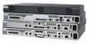
14 13X 15 16 17 18 19 20 21 22 2X 23 24 23X 12X 14X 24X 3 Cisco ME 2400 SERIES 1 2 45 1 AC power connector 3 10/100 Fast Ethernet ports 2 Console port 4 Gigabit Ethernet SFP module ports 6 5 Ground connector 6 Cable lock Figure 1-2 Cisco ME 2400 DC Ethernet Access Switch Front Panel - Cisco 2431 | Hardware Installation Guide - Page 22
supports these Cisco SFP modules: • 100BASE-BX • 100BASE-FX • 100BASE-LX • 1000BASE-BX • 1000BASE-LX/LH • 1000BASE-SX • 1000BASE-T • 1000BASE-ZX • CWDM For more information about these SFP modules, see your SFP module documentation. Cisco ME 2400 Ethernet Access Switch Hardware Installation Guide - Cisco 2431 | Hardware Installation Guide - Page 23
and port LEDs to monitor switch activity and performance. Figure 1-4 shows the switch System LED. Figure 1-4 Cisco ME Switch System LED 1 SYSTEM 1A-01.0R50AA-2,T45IN00GV-60~ HZ CONSOLE 1 System LED 132661 OL-7678-01 Cisco ME 2400 Ethernet Access Switch Hardware Installation Guide 1-5 - Cisco 2431 | Hardware Installation Guide - Page 24
Port is disabled. Rear Panel Description The Cisco ME switch rear panel has a cable lock and an exhaust fan. (See Figure 1-5.) Figure 1-5 Cisco ME Switch Rear Panel 132662 1 Cable lock 2 Fan exhaust 1 2 23 3 Ground connector Cisco ME 2400 Ethernet Access Switch Hardware Installation Guide - Cisco 2431 | Hardware Installation Guide - Page 25
fully configure and monitor the switch from the CLI. You can access the CLI either by connecting your management station directly to the switch console port or by using Telnet from a remote management station. See the switch command reference on Cisco.com for more information. For setup instructions - Cisco 2431 | Hardware Installation Guide - Page 26
of network configuration concepts. The software configuration guide also provides examples of network configurations that use the switch to create dedicated network segments that are interconnected through Ethernet connections. Cisco ME 2400 Ethernet Access Switch Hardware Installation Guide - Cisco 2431 | Hardware Installation Guide - Page 27
Switch Operation, page 2-7 • Installing the Switch, page 2-7 • Installing and Removing SFP Modules, page 2-18 • Inserting and Removing the SFP Module Patch Cable, page 2-21 • Connecting to the 10/100 Ports Statement 43 OL-7678-01 Cisco ME 2400 Ethernet Access Switch Hardware Installation Guide 2-1 - Cisco 2431 | Hardware Installation Guide - Page 28
Statement 1003 Warning Read the installation instructions before connecting the system devices, install the stabilizers before mounting or servicing the unit in the rack. Statement 1006 Warning Class 1 laser product. Statement 1008 Cisco ME 2400 Ethernet Access Switch Hardware Installation Guide - Cisco 2431 | Hardware Installation Guide - Page 29
1047 Warning When installing or replacing the unit, the ground connection must always be made first and disconnected last. Statement 1046 Warning No user-serviceable parts inside. Do not open. Statement 1073 OL-7678-01 Cisco ME 2400 Ethernet Access Switch Hardware Installation Guide 2-3 - Cisco 2431 | Hardware Installation Guide - Page 30
for ESD protection during servicing. Installation Guidelines When you determine where to place the switch, be sure to observe these requirements: • For copper Ethernet ports, including 10/100 ports and 1000BASE-T SFP module ports, cable lengths from the switch to connected devices can be up to - Cisco 2431 | Hardware Installation Guide - Page 31
away from sources of electrical noise, such as radios, power lines, and fluorescent lighting fixtures. Make sure that the cabling is safely away from other devices that might damage the cables. OL-7678-01 Cisco ME 2400 Ethernet Access Switch Hardware Installation Guide 2-5 - Cisco 2431 | Hardware Installation Guide - Page 32
support. Return all packing material to the shipping container, and save it. The switch is shipped with these items: • Cisco ME 3400 and Cisco ME 2400 Ethernet Access Switches Getting Started Guide • Regulatory Compliance and Safety Information for the Cisco ME 3400 and Cisco ME 2400 Ethernet Access - Cisco 2431 | Hardware Installation Guide - Page 33
the instructions described in these procedures: • Removing Screws from the Switch, page 2-8 • Attaching Brackets to the Switch, page 2-9 • Mounting the Switch in a Rack, page 2-15 • Attaching the Cable Guide, page 2-16 OL-7678-01 Cisco ME 2400 Ethernet Access Switch Hardware Installation Guide 2-7 - Cisco 2431 | Hardware Installation Guide - Page 34
in the switch chassis so that mounting brackets can be attached. Figure 2-1 shows how to remove the chassis screws in a Cisco ME switch. Figure 2-1 Removing Screws from the Cisco ME Switch 132686 Cisco ME 2400 SERIES 1 2 Cisco ME 2400 Ethernet Access Switch Hardware Installation Guide 2-8 OL - Cisco 2431 | Hardware Installation Guide - Page 35
RCKMNT-24IN-1RU (700-13248-XX), and see Attaching Brackets to 24-Inch Racks, page 2-12. • For ETSI racks, use part number RCKMNT-ETSI-1RU= (700-19781-XX), and see Attaching Brackets for ETSI Racks, page 2-14. 132869 OL-7678-01 Cisco ME 2400 Ethernet Access Switch Hardware Installation Guide 2-9 - Cisco 2431 | Hardware Installation Guide - Page 36
SYSTEM 1A-01.0R50AA-2,T45IN00GV-60~ HZ CONSOLE 132664 1 Phillips flat-head screws Figure 2-4 Attaching Brackets for 19-Inch Racks to a Cisco ME Switch, Rear Panel Forward 132666 1 1 Phillips flat-head screws 2-10 Cisco ME 2400 Ethernet Access Switch Hardware Installation Guide OL-7678-01 - Cisco 2431 | Hardware Installation Guide - Page 37
Cisco ME Switch, Figure 2-8 on page 2-12 Figure 2-6 1 Attaching Brackets for 23-Inch Racks to a Cisco ME Switch, Front Panel Forward 143307 1 Phillips flat-head screws SYSTEM 1A-01.0R50AA-2,T45IN00GV-60~ HZ CONSOLE OL-7678-01 Cisco ME 2400 Ethernet Access Switch Hardware Installation Guide - Cisco 2431 | Hardware Installation Guide - Page 38
2-9 on page 2-13 • Attaching Brackets for 24-Inch Racks to a Cisco ME Switch, Rear Panel Forward, Figure 2-10 on page 2-13 • Attaching Brackets for 24-Inch Telco Racks to a Cisco ME Switch, Figure 2-11 on page 2-13 2-12 Cisco ME 2400 Ethernet Access Switch Hardware Installation Guide OL-7678-01 - Cisco 2431 | Hardware Installation Guide - Page 39
a Cisco ME Switch, Rear Panel Forward 132667 1 1 Phillips flat-head screws Figure 2-11 Attaching Brackets for 24-Inch Telco Racks to a Cisco ME Switch Cisco ME 2400 SERIES 1 2 1 1 Phillips flat-head screws 132700 OL-7678-01 Cisco ME 2400 Ethernet Access Switch Hardware Installation Guide - Cisco 2431 | Hardware Installation Guide - Page 40
SYSTEM 1A-01.0R50AA-2,T45IN00GV-60~ HZ CONSOLE 132865 1 Phillips flat-head screws Figure 2-13 Attaching Brackets for ETSI Racks to a Cisco ME Switch, Rear Panel Forward 132868 1 1 Phillips flat-head screws 2-14 Cisco ME 2400 Ethernet Access Switch Hardware Installation Guide OL-7678-01 - Cisco 2431 | Hardware Installation Guide - Page 41
on page 2-7. • Connect to a 10/100 port and either run the Initial Configuration Dialog or use the CLI to set up your switch. See the Cisco ME 3400 and ME 2400 Ethernet Access Switches Getting Started Guide for instructions. • Connect to the front-panel ports. See the "Connecting to the 10/100 - Cisco 2431 | Hardware Installation Guide - Page 42
~ HZ CONSOLE 12 1X 34 56 78 9 10 11 12 11X 13 14 13X 15 16 17 18 19 20 21 22 2X 23 24 23X 12X 14X 24X Cisco ME 2400 SERIES 1 2 132689 1 Cable guide screw Wall-Mounting To install the switch on a wall, follow the instructions in these procedures: • Attaching the Brackets to the - Cisco 2431 | Hardware Installation Guide - Page 43
on page 2-7. • Connect to a 10/100 port, and run the Initial Configuration Dialog. See the Cisco ME 3400 and ME 2400 Ethernet Access Switches Getting Started Guide for instructions. • Connect to the front-panel ports. See the "Connecting to the 10/100 Ports" section on page 2-22 and the "Connecting - Cisco 2431 | Hardware Installation Guide - Page 44
on page 2-7. • Connect to a 10/100 port, and run the Initial Configuration Dialog. See the Cisco ME 3400 and ME 2400 Ethernet Access Switches Getting Started Guide for instructions. • Connect to the front-panel ports. See the "Connecting to the 10/100 Ports" section on page 2-22 and the "Connecting - Cisco 2431 | Hardware Installation Guide - Page 45
the fiber-optic SFP module port or the rubber caps from the fiber-optic cable until you are ready to connect the cable. The plugs and caps protect the SFP module ports and cables from contamination and ambient light. OL-7678-01 Cisco ME 2400 Ethernet Access Switch Hardware Installation Guide 2-19 - Cisco 2431 | Hardware Installation Guide - Page 46
plug into the cable end. Tip For reattachment, Screwdriver Cisco ME 2400 SERIES 1 ports of the SFP module to keep the optical interfaces clean. Place the removed SFP module in an antistatic bag or other protective environment. 2-20 Cisco ME 2400 Ethernet Access Switch Hardware Installation Guide - Cisco 2431 | Hardware Installation Guide - Page 47
22 2X 23 24 23X 12X 14X 24X Cisco ME 2400 SERIES 1 2 Cisco ME 2400 SERIES 1 2 132694 To remove an SFP module patch cable from the SFP module slot, release the connector, and pull it from the SFP module slot. OL-7678-01 Cisco ME 2400 Ethernet Access Switch Hardware Installation Guide 2-21 - Cisco 2431 | Hardware Installation Guide - Page 48
device. See Chapter 3, "Troubleshooting," for solutions to cabling problems. Note On user network interface (UNI) ports, the port LED is green after the link is established. It does not turn amber because. STP is not supported. 2-22 Cisco ME 2400 Ethernet Access Switch Hardware Installation Guide - Cisco 2431 | Hardware Installation Guide - Page 49
module port (see Figure 2-25). Figure 2-25 Connecting to a Fiber-Optic SFP Module Port 132679 Cisco ME 3400 SERIES 1 2 1 LC connector Step 3 Insert the other cable end into a fiber-optic connector on a target device. OL-7678-01 Cisco ME 2400 Ethernet Access Switch Hardware Installation Guide - Cisco 2431 | Hardware Installation Guide - Page 50
to a copper 10/100 or 1000BASE-T SFP module port on the switch, regardless of the type of device on the other end of the connection. Step 2 Insert the other cable end in an RJ-45 connector on a target device. 2-24 Cisco ME 2400 Ethernet Access Switch Hardware Installation Guide OL-7678-01 - Cisco 2431 | Hardware Installation Guide - Page 51
a Cisco ME switch. For setup instructions that use the CLI setup program, go to Appendix D, "Configuring the Switch with the CLI-Based Setup Program." • Start an SNMP application such as the CiscoView application. OL-7678-01 Cisco ME 2400 Ethernet Access Switch Hardware Installation Guide 2-25 - Cisco 2431 | Hardware Installation Guide - Page 52
Where to Go Next Chapter 2 Switch Installation 2-26 Cisco ME 2400 Ethernet Access Switch Hardware Installation Guide OL-7678-01 - Cisco 2431 | Hardware Installation Guide - Page 53
from a Simple Network Management Protocol (SNMP) workstation. See the switch software configuration guide, the switch command reference, or the documentation that came with your IE2100 or SNMP application for details. This chapter describes these topics for troubleshooting problems: • Understanding - Cisco 2431 | Hardware Installation Guide - Page 54
device exceeds the SFP module cabling guidelines. • Reduce the cable length to within the recommended distances. • See your repeater documentation for cabling guidelines. • See your SFP module documentation for cabling guidelines. Cisco ME 2400 Ethernet Access Switch Hardware Installation Guide - Cisco 2431 | Hardware Installation Guide - Page 55
global configuration command to verify the port status, and enter a time interval to recover from the error-disabled state. See the switch command reference guide for information on the errdisable recovery command. OL-7678-01 Cisco ME 2400 Ethernet Access Switch Hardware Installation Guide 3-3 - Cisco 2431 | Hardware Installation Guide - Page 56
global configuration command to verify the port status, and enter a time interval to recover from the error-disabled state. Refer to the switch command reference guide for information on the errdisable recovery command. Cisco ME 2400 Ethernet Access Switch Hardware Installation Guide 3-4 OL - Cisco 2431 | Hardware Installation Guide - Page 57
A Power consumption 25 W (typical), 30 W (maximum), 102 BTUs per hour Power dissipation 25 W Physical Dimensions Weight 8.2 lb (3.72 kg) Dimensions (H x D x W) 1.75 x 17.5 x 9.52 in. ( 4.45 x 444.5 x 24.18 cm) OL-7678-01 Cisco ME 2400 Ethernet Access Switch Hardware Installation Guide A-1 - Cisco 2431 | Hardware Installation Guide - Page 58
Appendix A Technical Specifications Cisco ME 2400 Ethernet Access Switch Hardware Installation Guide A-2 OL-7678-01 - Cisco 2431 | Hardware Installation Guide - Page 59
the ports to other devices, such as switches or repeaters, you can use a two or four twisted-pair crossover cable. Figure B-5 shows the two twisted-pair crossover cable schematics. Figure B-7 shows the four twisted-pair crossover cable schematics. OL-7678-01 Cisco ME 2400 Ethernet Access Switch - Cisco 2431 | Hardware Installation Guide - Page 60
Warning Invisible laser radiation may be emitted from disconnected fibers or connectors. Do not stare into beams or view directly with optical instruments. Statement 1051 Cisco ME 2400 Ethernet Access Switch Hardware Installation Guide B-2 OL-7678-01 - Cisco 2431 | Hardware Installation Guide - Page 61
twisted-pair cables for connecting to 10BASE-Tand 100BASE-TX-compatible devices. Figure B-4 Switch 3 TD+ 6 TD- 1 RD+ 2 RD- Two Twisted-Pair Straight-Through Cable Schematic Router or PC 3 RD+ 6 RD- 1 TD+ 2 TD- H5578 OL-7678-01 Cisco ME 2400 Ethernet Access Switch Hardware Installation Guide B-3 - Cisco 2431 | Hardware Installation Guide - Page 62
1 TPO+ 2 TPO3 TP1+ 6 TP1- 65271 4 NC 5 NC 7 NC 8 NC Four Twisted-Pair Crossover Cable Schematics for 1000BASE-T Ports Switch 1 TP0+ 2 TP03 TP1+ 6 TP1- 4 TP2+ 5 TP27 TP3+ 8 TP3- 4 TP2+ 5 TP27 TP3+ 8 TP3- 65274 Cisco ME 2400 Ethernet Access Switch Hardware Installation Guide B-4 OL-7678-01 - Cisco 2431 | Hardware Installation Guide - Page 63
Console Port Signaling Using a DB-9 Adapter Switch Console Port (DTE) Signal RTS DTR TxD GND GND RxD DSR CTS RJ-45-to-DB-9 Terminal Adapter DB-9 Pin 8 6 2 5 5 3 4 7 Console Device Signal CTS DSR RxD GND GND TxD DTR RTS OL-7678-01 Cisco ME 2400 Ethernet Access Switch Hardware Installation Guide - Cisco 2431 | Hardware Installation Guide - Page 64
B-2 Switch Console Port (DTE) Signal RTS DTR TxD GND GND RxD DSR CTS Console Port Signaling Using a DB-25 Adapter RJ-45-to-DB-25 Terminal Adapter DB-25 Pin 5 6 3 7 7 2 20 4 Console Device Signal CTS DSR RxD GND GND TxD DTR RTS Cisco ME 2400 Ethernet Access Switch Hardware Installation Guide - Cisco 2431 | Hardware Installation Guide - Page 65
copper wiring for Network Equipment Building Systems (NEBS) installation. This guideline servicing. Preparing for Installation Locate the DC terminal block plug, the ground lug, and the two number-10-32 screws in the DC-switch Cisco ME 2400 Ethernet Access Switch Hardware Installation Guide C-1 - Cisco 2431 | Hardware Installation Guide - Page 66
± 0.02 in. (0.5 mm) 60528 Insulation Wire lead Step 3 Slide the open end of the ground lug over the exposed area of the 6-gauge wire. Step 4 Using a Panduit crimping tool, crimp the ground lug to the 6-gauge wire. Cisco ME 2400 Ethernet Access Switch Hardware Installation Guide C-2 OL-7678-01 - Cisco 2431 | Hardware Installation Guide - Page 67
each ground-lug screw to 15 lbf-in. (240 ounce-force inches [ozf-in.]). Figure C-3 shows how to torque the ground screws on a Cisco ME DC switch. Figure C-3 Torquing Ground-Lug Screws 132854 1 Torque to 15 lbf-in. OL-7678-01 1 Cisco ME 2400 Ethernet Access Switch Hardware Installation Guide C-3 - Cisco 2431 | Hardware Installation Guide - Page 68
2X 23 24 23X 12X 14X 24X Cisco ME 3400 SERIES 1 2 1 2 1 Telco rack 2 Grounding wire Figure C-5 Connecting the Grounding Wire to the Rack (Grounding) from the Rear-Panel Ground Connector 1 132857 1 Telco rack 2 Grounding wire Cisco ME 2400 Ethernet Access Switch Hardware Installation Guide - Cisco 2431 | Hardware Installation Guide - Page 69
. Use a 3/16-inch flat-head services the DC circuit, switch the circuit breaker to the OFF position, and tape the switch handle of the circuit breaker in the OFF position. Locate the terminal block plug (see Figure C-6). OL-7678-01 Cisco ME 2400 Ethernet Access Switch Hardware Installation Guide - Cisco 2431 | Hardware Installation Guide - Page 70
more than the recommended amount of wire can leave exposed wire from the terminal block plug after installation. Figure C-8 Stripping the DC-Input Power Source Wire 0.25 in. (6.3 mm) ± 0. from the terminal block. Cisco ME 2400 Ethernet Access Switch Hardware Installation Guide C-6 OL-7678-01 - Cisco 2431 | Hardware Installation Guide - Page 71
terminal block captive screw (above the installed wire lead) to 4.5 lbf-in. (72 ozf-in.). (See Figure C-10.) Caution Do not overtorque the terminal-block captive screws. The recommended maximum torque is 4.5 lbf-in. OL-7678-01 Cisco ME 2400 Ethernet Access Switch Hardware Installation Guide C-7 - Cisco 2431 | Hardware Installation Guide - Page 72
(negative) Feed A 3 Return (positive) Feed B 4 Supply (negative) Feed B Step 8 Insert the terminal block plug in the terminal block header on the front panel of the switch. (See Figure C-12). Cisco ME 2400 Ethernet Access Switch Hardware Installation Guide C-8 OL-7678-01 - Cisco 2431 | Hardware Installation Guide - Page 73
the Terminal Block in the Block Header ICNUPR+AURTE-N36TB+-2 -72 V - 1A SYSTEM CONSOLE 132851 Step 9 Remove the tape from the circuit-breaker switch handle, and move the circuit-breaker handle to the on position. OL-7678-01 Cisco ME 2400 Ethernet Access Switch Hardware Installation Guide C-9 - Cisco 2431 | Hardware Installation Guide - Page 74
Wiring the DC-Input Power Source Appendix C Connecting to DC Power C-10 Cisco ME 2400 Ethernet Access Switch Hardware Installation Guide OL-7678-01 - Cisco 2431 | Hardware Installation Guide - Page 75
Console Port" section on page D-3 • "Starting the Terminal-Emulation Software" section on page D-4 • "Connecting to a Power Source" section on page D-5 • "Entering the Initial Configuration Information" section on page D-5 OL-7678-01 Cisco ME 2400 Ethernet Access Switch Hardware Installation Guide - Cisco 2431 | Hardware Installation Guide - Page 76
+-2 -72 V - 1A SYSTEM CONSOLE 12 1X 34 56 78 9 10 11 12 11X 13 14 13X 15 16 17 18 19 20 21 22 2X 23 24 23X 12X 14X 24X Cisco ME 2400 SERIES 1 2 2 3 1 Cisco ME DC switch 2 DC power cord Cisco ME 2400 Ethernet Access Switch Hardware Installation Guide D-2 132698 OL-7678-01 - Cisco 2431 | Hardware Installation Guide - Page 77
-45 connector into the console port on the rear of a switch, as shown in Figure D-1 and Figure D-2. Attach the DB-9 female DTE of the adapter cable to a PC serial port, or attach an appropriate adapter to the terminal. OL-7678-01 Cisco ME 2400 Ethernet Access Switch Hardware Installation Guide D-3 - Cisco 2431 | Hardware Installation Guide - Page 78
using a PC or terminal. Configure the baud rate and character format of the PC or terminal to match these console port default characteristics: • 9600 baud • 8 data bits • 1 stop bit • No parity • None (flow control) Cisco ME 2400 Ethernet Access Switch Hardware Installation Guide D-4 OL-7678-01 - Cisco 2431 | Hardware Installation Guide - Page 79
information from your network administrator before you complete the setup program: • Switch IP address • Subnet mask (IP netmask) • Default gateway (router) • Enable secret password • Enable password • Telnet password OL-7678-01 Cisco ME 2400 Ethernet Access Switch Hardware Installation Guide D-5 - Cisco 2431 | Hardware Installation Guide - Page 80
and subnet masks shown below are examples. Configuring interface vlan1: Configure IP on this interface? [yes]: yes IP address for this interface: 10.4.120.106 Subnet mask for this interface [255.0.0.0]: 255.0.0.0 Cisco ME 2400 Ethernet Access Switch Hardware Installation Guide D-6 OL-7678-01 - Cisco 2431 | Hardware Installation Guide - Page 81
Switch> prompt through the console port by using a terminal program or through the network by using Telnet. For configuration information, see the switch software configuration guide or the switch command reference. OL-7678-01 Cisco ME 2400 Ethernet Access Switch Hardware Installation Guide D-7 - Cisco 2431 | Hardware Installation Guide - Page 82
Entering the Initial Configuration Information Appendix D Configuring the Switch with the CLI-Based Setup Program Cisco ME 2400 Ethernet Access Switch Hardware Installation Guide D-8 OL-7678-01 - Cisco 2431 | Hardware Installation Guide - Page 83
See also connectors and cables cabling 10/100 ports 2-22, B-1 auto-MDIX 2-24 pinouts B-4 See also connectors and cables cautions viii Cisco IOS command-line interface 1-7 CiscoView 1-7 CLI 1-7 accessing through console port D-1 Cisco ME 2400 Ethernet Access Switch Hardware Installation Guide IN-1 - Cisco 2431 | Hardware Installation Guide - Page 84
1-8 front panel 10/100 ports 1-3 clearance 2-5 description 1-2 to 1-6 LEDs 1-5 SFP module ports 1-4 G ground conductor warning 2-3 ground connection warning 2-3, C-2 grounded equipment warning C-2 H HP OpenView 1-8 IN-2 Cisco ME 2400 Ethernet Access Switch Hardware Installation Guide OL-7678-01 - Cisco 2431 | Hardware Installation Guide - Page 85
four twisted-pair 1000BASE-T ports B-4 two twisted-pair B-3 plug-socket combination warning 2-3 port LEDs 1-6 ports 10/100 1-2, 1-3 numbering of 10/100 1-3 numbering of SFP module ports 1-3 POST LEDs 3-1, D-5 results 3-1, D-5 Cisco ME 2400 Ethernet Access Switch Hardware Installation Guide IN-3 - Cisco 2431 | Hardware Installation Guide - Page 86
2-18 technical specifications A-1 telco racks 2-7 Telnet, and accessing the CLI 1-7 temperature, operating A-1 terminal emulation software D-4 trained and qualified personnel warning 2-3 troubleshooting 3-1 to 3-3 IN-4 Cisco ME 2400 Ethernet Access Switch Hardware Installation Guide OL-7678-01 - Cisco 2431 | Hardware Installation Guide - Page 87
2-2 short-circuit (overcurrent) protection 2-2, C-5 short-circuit protection 2-3 stacking chassis 2-2 trained and qualified personnel 2-3 two-poled disconnect 2-3 two-poled disconnect device C-5 wall-mounting 2-2 OL-7678-01 Cisco ME 2400 Ethernet Access Switch Hardware Installation Guide IN-5 - Cisco 2431 | Hardware Installation Guide - Page 88
Index IN-6 Cisco ME 2400 Ethernet Access Switch Hardware Installation Guide OL-7678-01
-
 1
1 -
 2
2 -
 3
3 -
 4
4 -
 5
5 -
 6
6 -
 7
7 -
8
-
9
-
10
-
11
-
12
-
13
-
14
-
15
-
16
-
17
-
18
-
19
-
20
-
21
-
22
-
23
-
24
-
25
-
26
-
27
-
28
-
29
-
30
-
31
-
32
-
33
-
34
-
35
-
36
-
37
-
38
-
39
-
40
-
41
-
42
-
43
-
44
-
45
-
46
-
47
-
48
-
49
-
50
-
51
-
52
-
53
-
54
-
55
-
56
-
57
-
58
-
59
-
60
-
61
-
62
-
63
-
64
-
65
-
66
-
67
-
68
-
69
-
70
-
71
-
72
-
73
-
74
-
75
-
76
-
77
-
78
-
79
-
80
-
81
-
82
-
83
-
84
-
85
-
86
-
87
-
88
 |
 |

Corporate Headquarters
Cisco Systems, Inc.
170 West Tasman Drive
San Jose, CA 95134-1706
USA
Tel: 408 526-4000
800 553-NETS (6387)
Fax: 408 526-4100
Cisco ME 2400 Ethernet Access Switch
Hardware Installation Guide
November 2005
Text Part Number: OL-7678-01