Cisco 2514 Getting Started Guide
Cisco 2514 - Router - EN Manual
 |
View all Cisco 2514 manuals
Add to My Manuals
Save this manual to your list of manuals |
Cisco 2514 manual content summary:
- Cisco 2514 | Getting Started Guide - Page 1
GETTING STARTED GUIDE Cisco 2500 Series Wireless Controller May 2011 Revised June 2, 2011 1 About This Guide 2 Unpacking and Preparing the Controller for Operation 3 Installing the Controller 4 Running the Bootup Script and Power-On Self Test 5 Logging into the Controller 6 Connecting to the Network - Cisco 2514 | Getting Started Guide - Page 2
Guide This guide is designed to help you install and minimally configure your Cisco 2504 Wireless Controller (2504 controller), which is part of the Cisco equipment and receiver. • Connect the equipment to an outlet on a circuit different from that to which the receiver is connected. • Consult the - Cisco 2514 | Getting Started Guide - Page 3
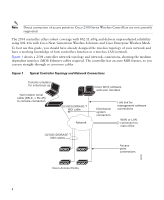
(location), award-winning RF management, quality of services for mobility services such as voice and video, and OEAP support for the Teleworker solution. The 2504 controllers supports up to 50 lightweight access points in increments of 5 access points with a minimum of 5 access points, making it - Cisco 2514 | Getting Started Guide - Page 4
Topology and Network Connections Console emulator for initial boot-up Null modem serial cable (DB-9 -> RJ-45) to console connection Cisco WCS software, web user interface 10/100/1000BASE-T MDI cable Network Distribution system connection LAN link for management software connections WAN or LAN - Cisco 2514 | Getting Started Guide - Page 5
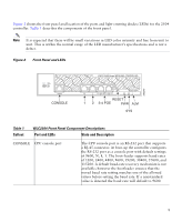
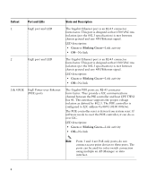
an RS-232 port that supports a RJ-45 connector. At boot-up the controller configures the RS-232 port as a console port with default settings of 9600, N, 8, 1. The boot-loader supports baud rates of 1200, 2400, 4800, 9600, 19200, 38400, 57600, and 115200. A default baud-rate recovery mechanism is not - Cisco 2514 | Getting Started Guide - Page 6
are RJ-45 connector form-factor. They provide a I2C communications channel between the PSE controller and host CPU TWSI bus #1. This interface supports the proper voltage isolation as defined by 802.3. The POE controller is configured to I2C address 0x40/41 (0100 000r/w). The POE controller reset is - Cisco 2514 | Getting Started Guide - Page 7
description: • Blinking Green-Controller image upgrading. • Amber-Controller status activity, such as firmware upgrade. • Blinking Amber-Controller error. For example, a temperature error exists. Caution Do not connect a Power over Ethernet (PoE) cable to the console port. Doing so will damage the - Cisco 2514 | Getting Started Guide - Page 8
seconds before reconnecting an access point to the controller. Controller Back Panel and Components 282250 POWER 48VDC Cable Lock Slot Table 2 Controller Back Panel and Description The 48 V input power is provided via an external AC/DC adapter. Power is provided to the system board from the 48 - Cisco 2514 | Getting Started Guide - Page 9
with factory-supplied power cord and mounting hardware - Network, operating system service network, and access point cables as required • Command-line interface (CLI) console - VT-100 terminal emulator on CLI console (PC, laptop, or palmtop) - Null modem serial cable to connect CLI console and - Cisco 2514 | Getting Started Guide - Page 10
a username and password and the configured username and password cannot be the same. • A management interface (DS Port or network interface port) IP address, such as 10.40.0.4. • A management interface netmask address, such as 255.255.255.0. • A management interface default router IP address, such - Cisco 2514 | Getting Started Guide - Page 11
if you are configuring a RADIUS server, such as 10.40.0.3, 1812, and mysecretcode. • The country code for this installation. Enter help to see a list or refer to the Cisco Wireless LAN Controller Configuration Guide for country code information. This guide is available at cisco.com. • Status of - Cisco 2514 | Getting Started Guide - Page 12
a Rack Mounting the Controller on a Desktop or Shelf Before mounting the controller on a desktop or shelf, install the rubber feet located in accessory kit shipped with the controller. To install the rubber feet to the controller, follow these steps: Step 1 Step 2 Locate the adhesive strip with - Cisco 2514 | Getting Started Guide - Page 13
installation: • Connecting the Controller Console Port • Securing the Power Adapter Cable • Connecting to the Network For configuration instructions about using the CLI setup from Cisco. The kit part number is AIR-CT2504-RMNT. Warning Read the wall-mounting carefully before beginning installation. - Cisco 2514 | Getting Started Guide - Page 14
each side of the controller) Step 2 Mount the 2504 controller on the wall with the front panel facing down, as shown Figure 6. For the best support of the controller and cables, make sure the controller is attached securely to wall studs or to a firmly attached plywood mounting backboard. 14 - Cisco 2514 | Getting Started Guide - Page 15
is mounted on the wall, perform the following tasks to complete the installation: • Connecting the Controller Console Port • Securing the Power Adapter Cable • Connecting to the Network For configuration instructions about using the CLI setup program, see the "Running the Bootup Script and Power-On - Cisco 2514 | Getting Started Guide - Page 16
Warning Read the wall-mounting carefully before beginning installation. Failure to use the correct hardware or to follow the correct procedures could result in a hazardous situation to people and damage to the system. Statement - Cisco 2514 | Getting Started Guide - Page 17
Screws 282085 2 1 2 1 Front panel (facing down) 2 Mounting screws Step 5 After the controller is mounted ion the wall, perform the following tasks to complete the installation: • Connecting the Controller Console Port • Securing the Power Adapter Cable • Connecting to the Network 17 - Cisco 2514 | Getting Started Guide - Page 18
Step 6 For configuration instructions about using the CLI setup program, see the "Running the Bootup If the rack is provided with stabilizing devices, install the stabilizers before mounting or servicing the unit in the rack. Statement 1006 To install the controller in a rack, follow these steps - Cisco 2514 | Getting Started Guide - Page 19
282082 Figure 9 Attaching the 19-Inch Brackets to the Side of the Controller. 1 RACK MOUNT 1 1 #10-32 flat head screws (mounting screws for each side of the controller) Step 2 After the brackets are attached to the sides of the controller, insert the controller into the 19-inch rack. Use either the - Cisco 2514 | Getting Started Guide - Page 20
is mounted in the rack, perform the following tasks to complete the installation: • Connecting the Controller Console Port • Securing the Power Adapter Cable • Connecting to the Network For configuration instructions about using the CLI setup program, see the "Running the Bootup Script and Power-On - Cisco 2514 | Getting Started Guide - Page 21
). To connect the PC to the controller console port, follow these steps: Step 1 Step 2 Step 3 Plug the RJ-45 connector on a null-modem serial cable into the controller console port and the other end of the cable into the serial port of the PC. Start the PC terminal emulation program. Configure the - Cisco 2514 | Getting Started Guide - Page 22
Wrap the power adapter cable through the plastic security clip as shown in Figure 11. Figure 11 Plastic Relief Clip Step 2 Fasten the security clip with a screw to the existing hole on the back panel on the 2504 controller (see Figure 12). Figure 12 Securing the Power Adapter Cable 1 3 2 22 281918 - Cisco 2514 | Getting Started Guide - Page 23
its microcode into memory, verifies its operating system software load, and initializes itself with its stored configurations. Before performing this test, you should have connected your PC to the CLI console on the controller as described in the "Connecting the Controller Console Port" section on - Cisco 2514 | Getting Started Guide - Page 24
to access the Boot Menu... Continue booting the controller or press Esc to access the following menu Boot Loader Menu 1. Run primary image (7.0.114.76) - Active 2. Run backup image (7.0.114.75) 3. Change active boot image 4. Clear configuration 5. Format FLASH Drive 6. Manually update images - Cisco 2514 | Getting Started Guide - Page 25
Installing ether-pow driver - 0x6008 starting pid 805, tty '/dev/ttyS0': '/usr/bin/gettyOrMwar' Cryptographic library self-test....passed! XML config selected Validating XML configuration octeon_device_init: found 1 DPs /dev/fpga: No such device or address readCPUConfigData: cardid 0x6060001 Cisco - Cisco 2514 | Getting Started Guide - Page 26
Services: Web Server: ok CLI: ok Secure Web: Web Authentication Certificate not found (error). If you cannot access management interface via HTTPS please reconfigure Virtual Interface. License Agent: ok (Cisco Controller)> Step 4 If desired, press Esc key to interrupt the boot process and access - Cisco 2514 | Getting Started Guide - Page 27
or press Esc to access the following menu: 1. Run primary image (7.0.114.76) - Active 2. Run backup image (7.0.114.75) 3. Change active boot image 4. Clear configuration 5. Format FLASH Drive 6. Manually update images Enter selection: If you did not press Esc, the boot process continues and takes - Cisco 2514 | Getting Started Guide - Page 28
Data Transport Link Layer: ok Starting Access Control List Services: ok Starting System Interfaces: ok Starting Client Troubleshooting Service: ok Starting Management Frame Protection: ok Starting Certificate Database: ok Starting VPN Services: ok Starting Licensing Services: ok Starting LWAPP: ok - Cisco 2514 | Getting Started Guide - Page 29
. Welcome to the Cisco Wizard Configuration Tool Use the '-' character to backup System Name [Cisco_d9:16:24]: Note The startup wizard runs the first time that you power on the controller. The second time you power it on, the controller prompts you for a login ID and password. Using the Startup - Cisco 2514 | Getting Started Guide - Page 30
is no default administrative password, you must enter a password. Enter the IP address of the management interface. The management interface is the default interface for in-band management of the controller and connectivity to enterprise services such as AAA servers. You can access the controller - Cisco 2514 | Getting Started Guide - Page 31
and controller redundancy while an RF group facilitates scalable, system-wide dynamic RF management. Network Name (SSID) Enter the network name, or service set identifier (SSID). This is the default SSID that the access points use when they join a controller. Configure DHCP Bridging Mode Enter - Cisco 2514 | Getting Started Guide - Page 32
Enable 802.11g Network Enable Auto-RF Configure a NTP server now? Enter the NTP server IP address Action Enter YES to allow clients to assign their own IP address or no to make clients request an IP address from a DHCP server. Values are YES or no. The default setting is YES. If you select YES - Cisco 2514 | Getting Started Guide - Page 33
Wizard Information (continued) Wizard Setting Enter a polling interval between 3600 and 604800 secs Action Enter the polling interval between 3600 and 604800 seconds. Configuration correct? Note This prompt only displays if YES was entered in the "Configure a NTP Server Now?" prompt. Enter yes - Cisco 2514 | Getting Started Guide - Page 34
You can set the automatic logout from 0 (never log out) to 160 minutes using the config serial timeout command. 6 Connecting to the Network Figure 13 shows the connection from the network (802.11 distribution system) to the controller. The connection uses 10/100/1000BASE-T Ethernet (RJ-45 physical - Cisco 2514 | Getting Started Guide - Page 35
to associate. Note Direct connection of access points to Cisco 2500 Series Wireless Controllers are not currently supported. You have prepared the controller for basic operation. Refer to the Cisco Wireless LAN Controller Configuration Guide for information on configuring the controller to meet the - Cisco 2514 | Getting Started Guide - Page 36
configuring your controller. The guide is available on cisco.com. Using the Reset Button The Reset button on the front panel of the controller becomes active after the controller boots. To reset the controller using the Reset button, follow these steps: Step 1 Connect a PC to the controller console - Cisco 2514 | Getting Started Guide - Page 37
and password at the prompts. If you have configured the controller, it reboots and loads the configuration. If you have not configured the controller, the configuration wizard appears. 7 What's New in Cisco Product Documentation For information on obtaining documentation, submitting a service - Cisco 2514 | Getting Started Guide - Page 38
to locate its translation in the translated safety warnings that accompanied this device. Statement 1071 SAVE THESE INSTRUCTIONS Waarschuwing BELANGRIJKE VEILIGHEIDSINSTRUCTIES Dit waarschuwingssymbool betekent gevaar. U verkeert in een situatie die lichamelijk letsel kan veroorzaken. Voordat - Cisco 2514 | Getting Started Guide - Page 39
des avertissements figurant dans les consignes de sécurité traduites qui accompagnent cet appareil, référez-vous au numéro de l'instruction situé à la fin de chaque avertissement. CONSERVEZ CES INFORMATIONS Warnung WICHTIGE SICHERHEITSHINWEISE Dieses Warnsymbol bedeutet Gefahr. Sie befinden sich - Cisco 2514 | Getting Started Guide - Page 40
Advarsel VIKTIGE SIKKERHETSINSTRUKSJONER Dette advarselssymbolet betyr fare. Du er i en situasjon som kan føre til skade på person. Før du begynner å arbeide med noe av utstyret, må du være oppmerksom på farene forbundet med elektriske kretser, og kjenne til standardprosedyrer for å forhindre - Cisco 2514 | Getting Started Guide - Page 41
Varning! VIKTIGA SÄKERHETSANVISNINGAR Denna varningssignal signalerar fara. Du befinner dig i en situation som kan leda till personskada. Innan du utför arbete på någon utrustning måste du vara medveten om farorna med elkretsar och känna till vanliga förfaranden för att förebygga olyckor. Använd - Cisco 2514 | Getting Started Guide - Page 42
42 - Cisco 2514 | Getting Started Guide - Page 43
43 - Cisco 2514 | Getting Started Guide - Page 44
44 - Cisco 2514 | Getting Started Guide - Page 45
45 - Cisco 2514 | Getting Started Guide - Page 46
46 - Cisco 2514 | Getting Started Guide - Page 47
is the danger of explosion if the battery is replaced incorrectly. Replace the battery only with the same or equivalent type recommended by the manufacturer. Dispose of used batteries according to the manufacturer's instructions. Statement 1015 Waarschuwing Er is ontploffingsgevaar als de batterij - Cisco 2514 | Getting Started Guide - Page 48
¡Advertencia! Existe peligro de explosión si la batería se reemplaza de manera incorrecta. Reemplazar la batería exclusivamente con el mismo tipo o el equivalente recomendado por el fabricante. Desechar las baterías gastadas según las instrucciones del fabricante. Varning! Explosionsfara vid - Cisco 2514 | Getting Started Guide - Page 49
tre mis à la masse. Ne jamais rendre inopérant le conducteur de masse ni utiliser l'équipement sans un conducteur de masse adéquatement installé. En cas de doute sur la mise à la masse appropriée disponible, s'adresser à l'organisme responsable de la sécurité électrique ou à un électricien. Warnung - Cisco 2514 | Getting Started Guide - Page 50
Advarsel Dette utstyret må jordes. Omgå aldri jordingslederen og bruk aldri utstyret uten riktig montert jordingsleder. Ta kontakt med fagfolk innen elektrisk inspeksjon eller med en elektriker hvis du er usikker på om det finnes velegnet jordning. Aviso Este equipamento deve ser aterrado. Nunca - Cisco 2514 | Getting Started Guide - Page 51
51 - Cisco 2514 | Getting Started Guide - Page 52
Statement 1040-Product Disposal Warning Ultimate disposal of this product should be handled according to all national laws and regulations. Statement 1040 Waarschuwing Het uiteindelijke wegruimen van dit product dient te geschieden in overeenstemming met alle nationale wetten en reglementen. - Cisco 2514 | Getting Started Guide - Page 53
Avvertenza Lo smaltimento di questo prodotto deve essere eseguito secondo le leggi e regolazioni locali. Advarsel Endelig kassering av dette produktet skal være i henhold til alle relevante nasjonale lover og bestemmelser. Aviso Deitar fora este produto em conformidade com todas as leis e - Cisco 2514 | Getting Started Guide - Page 54
54 - Cisco 2514 | Getting Started Guide - Page 55
Cable and AC Adapter When installing the product, please use the provided or designated connection cables/power cables/AC adaptors/batteries. Using any other cables/adaptors domestic environment, it may cause radio interference. Install and use the equipment according to the instruction manual. 55 - Cisco 2514 | Getting Started Guide - Page 56
, Inc. and/or its affiliates in the U.S. and other countries. A listing of Cisco's trademarks can be found at www.cisco.com/go/trademarks. Third party trademarks mentioned are the property of their respective owners. The use of the word partner does not imply a partnership relationship
-
 1
1 -
 2
2 -
 3
3 -
 4
4 -
 5
5 -
 6
6 -
 7
7 -
8
-
9
-
10
-
11
-
12
-
13
-
14
-
15
-
16
-
17
-
18
-
19
-
20
-
21
-
22
-
23
-
24
-
25
-
26
-
27
-
28
-
29
-
30
-
31
-
32
-
33
-
34
-
35
-
36
-
37
-
38
-
39
-
40
-
41
-
42
-
43
-
44
-
45
-
46
-
47
-
48
-
49
-
50
-
51
-
52
-
53
-
54
-
55
-
56
 |
 |

G
ETTING
S
TARTED
G
UIDE
Cisco 2500 Series Wireless Controller
May 2011
Revised June 2, 2011
1
About This Guide
2
Unpacking and Preparing the Controller for Operation
3
Installing the Controller
4
Running the Bootup Script and Power-On Self Test
5
Logging into the Controller
6
Connecting to the Network
7
What’s New in Cisco Product Documentation
8
Translated Safety Warnings