Cisco 2948G Hardware Installation Guide
Cisco 2948G - Catalyst Switch Manual
 |
UPC - 746320228884
View all Cisco 2948G manuals
Add to My Manuals
Save this manual to your list of manuals |
Cisco 2948G manual content summary:
- Cisco 2948G | Hardware Installation Guide - Page 1
Catalyst 2984G, 2948G-GE-TX, and 2980G Switch Hardware Installation Guide October 2003 Corporate Headquarters Cisco Systems, Inc. 170 West Tasman Drive San Jose, CA 95134-1706 USA http://www.cisco.com Tel: 408 526-4000 800 553-NETS (6387) Fax: 408 526-4100 Customer Order Number: DOC-786286= Text - Cisco 2948G | Hardware Installation Guide - Page 2
is for FCC compliance of Class B devices: The equipment described in this manual generates and may radiate radio-frequency energy. If it is not installed in accordance with Cisco's installation instructions, it may cause interference with radio and television reception. This equipment has been - Cisco 2948G | Hardware Installation Guide - Page 3
are the property of their respective owners. The use of the word partner does not imply a partnership relationship between Cisco and any other company. (0304R) Catalyst 2984G, 2948G-GE-TX, and 2980G Switch Hardware Installation Guide Copyright © 1999-2003, Cisco Systems, Inc. All rights reserved. - Cisco 2948G | Hardware Installation Guide - Page 4
- Cisco 2948G | Hardware Installation Guide - Page 5
Case xxv TAC Case Priority Definitions xxv Obtaining Additional Publications and Information xxvi Product Overview 1-1 Switch Description 1-1 GBIC Module Support 1-3 SFP Module Support 1-3 Switch Features 1-4 78-6286-05 Catalyst 2984G, 2948G-GE-TX, and 2980G Switch Hardware Installation Guide v - Cisco 2948G | Hardware Installation Guide - Page 6
10/100 and 10/100/1000 Ports 1-6 Catalyst 2948G and 2980G Switch Ports 1-7 Catalyst 2948G-GE-TX Switch Ports 1-7 Switch Components 1-7 Management Ports 1-8 Console Serial Port 1-8 10BASE-T and 10/100BASE-T Ports 1-8 Front Panel LEDs 1-8 Airflow 1-9 Power Supplies 1-11 2 C H A P T E R Site Planning - Cisco 2948G | Hardware Installation Guide - Page 7
3-17 Mounting the Catalyst 2948G-GE-TX Switch on a Table or Shelf 3-19 Connecting Power to the Switches 3-19 Connecting to 10/100 and 10/100/1000 Ports 3-20 Connecting a Terminal to the Console Serial and Ethernet Management Ports 3-22 Verifying Switch Operation 3-23 Configuring the Gigabit Ethernet - Cisco 2948G | Hardware Installation Guide - Page 8
Problems 5-3 Troubleshooting the Power Supply 5-4 Contacting Customer Service 5-5 A A P P E N D I X Specifications A-1 Console Serial Port A-1 10BASE-T and 10/100BASE-T Ethernet Management Ports A-2 Catalyst 2948G Switch Specifications A-2 Catalyst 2948G-GE-TX Switch Specifications A-5 Catalyst - Cisco 2948G | Hardware Installation Guide - Page 9
-AC-RPS) D-14 Attaching the Cisco RPS (model PWR675-AC-RPS-N1) D-15 Redundant Power Supply Connection Warning D-17 Switch Installation Warning D-18 Chassis Warning for Rack-Mounting and Servicing D-20 Contents 78-6286-05 Catalyst 2984G, 2948G-GE-TX, and 2980G Switch Hardware Installation Guide ix - Cisco 2948G | Hardware Installation Guide - Page 10
Contents Catalyst 2984G, 2948G-GE-TX, and 2980G Switch Hardware Installation Guide x 78-6286-05 - Cisco 2948G | Hardware Installation Guide - Page 11
Cisco Limited Warranty and Software License page from the Information Packet appears. d. Read the document online, or click the PDF icon to download and print the document in Adobe Portable Document Format (PDF). 78-6286-05 Catalyst 2984G, 2948G-GE-TX, and 2980G Switch Hardware Installation Guide - Cisco 2948G | Hardware Installation Guide - Page 12
a Return Materials Authorization (RMA) Number Contact the company from whom you purchased the product. If you purchased the product directly from Cisco, contact your Cisco Sales and Service Representative. Catalyst 2984G, 2948G-GE-TX, and 2980G Switch Hardware Installation Guide xii 78-6286-05 - Cisco 2948G | Hardware Installation Guide - Page 13
Warranty Terms Complete the information below, and keep it for reference. Company product purchased from Company telephone number Product model number Product serial number Maintenance contract number 78-6286-05 Catalyst 2984G, 2948G-GE-TX, and 2980G Switch Hardware Installation Guide xiii - Cisco 2948G | Hardware Installation Guide - Page 14
Cisco Limited Lifetime Hardware Warranty Terms Catalyst 2984G, 2948G-GE-TX, and 2980G Switch Hardware Installation Guide xiv 78-6286-05 - Cisco 2948G | Hardware Installation Guide - Page 15
how to prepare your site for the installation of the switch. Describes how to install the Catalyst 2948G, 2948G-GE-TX, and 2980G switches. Provides procedures for removing and installing chassis components. 78-6286-05 Catalyst 2984G, 2948G-GE-TX, and 2980G Switch Hardware Installation Guide xv - Cisco 2948G | Hardware Installation Guide - Page 16
• Software Configuration Guide-Catalyst 4500 Series, Catalyst 2948G, and Catalyst 2980G Switches • Command Reference-Catalyst 4500 Series, Catalyst 2948G, and Catalyst 2980G Switches • System Message Guide-Catalyst 4500 Series, Catalyst 2948G, and Catalyst 2980G Switches Catalyst 2984G, 2948G-GE-TX - Cisco 2948G | Hardware Installation Guide - Page 17
, such as passwords are in angle brackets. Notes use the following conventions: Note Means reader take note. Notes contain helpful suggestions or references to material not covered in the publication. 78-6286-05 Catalyst 2984G, 2948G-GE-TX, and 2980G Switch Hardware Installation Guide xvii - Cisco 2948G | Hardware Installation Guide - Page 18
or loss of data. Warnings use the following conventions: Warning IMPORTANT SAFETY INSTRUCTIONS This warning symbol means danger. You are in a situation that could cause raadplegen. BEWAAR DEZE INSTRUCTIES xviii Catalyst 2984G, 2948G-GE-TX, and 2980G Switch Hardware Installation Guide 78-6286-05 - Cisco 2948G | Hardware Installation Guide - Page 19
traduites qui accompagnent cet appareil, référez-vous au numéro de l'instruction situé à la fin de chaque avertissement. CONSERVEZ CES INFORMATIONS Warnung WICHTIGE . BEWAHREN SIE DIESE HINWEISE GUT AUF. 78-6286-05 Catalyst 2984G, 2948G-GE-TX, and 2980G Switch Hardware Installation Guide xix - Cisco 2948G | Hardware Installation Guide - Page 20
da instrução fornecido ao final de cada aviso para localizar sua tradução nos avisos de segurança traduzidos que acompanham este dispositivo. GUARDE ESTAS INSTRUÇÕES Catalyst 2984G, 2948G-GE-TX, and 2980G Switch Hardware Installation Guide xx 78-6286-05 - Cisco 2948G | Hardware Installation Guide - Page 21
som finns i slutet av varje varning för att hitta dess översättning i de översatta säkerhetsvarningar som medföljer denna anordning. SPARA DESSA ANVISNINGAR 78-6286-05 Catalyst 2984G, 2948G-GE-TX, and 2980G Switch Hardware Installation Guide xxi - Cisco 2948G | Hardware Installation Guide - Page 22
Conventions Preface xxii Catalyst 2984G, 2948G-GE-TX, and 2980G Switch Hardware Installation Guide 78-6286-05 - Cisco 2948G | Hardware Installation Guide - Page 23
.cisco.com/en/US/partner/ordering/ordering_place_order_ordering_t ool_launch.html All users can order annual or quarterly subscriptions through the online Subscription Store: http://www.cisco.com/go/subscription 78-6286-05 Catalyst 2984G, 2948G-GE-TX, and 2980G Switch Hardware Installation Guide - Cisco 2948G | Hardware Installation Guide - Page 24
Assistance Center (TAC) provides 24-hour, award-winning technical support services, online and over the phone. Cisco.com features the Cisco TAC website as an online starting point for technical assistance. xxiv Catalyst 2984G, 2948G-GE-TX, and 2980G Switch Hardware Installation Guide 78-6286-05 - Cisco 2948G | Hardware Installation Guide - Page 25
this URL: http://www.cisco.com/warp/public/687/Directory/DirTAC.shtml TAC Case Priority Definitions To ensure that all cases are reported in a standard format, Cisco has established case priority definitions. 78-6286-05 Catalyst 2984G, 2948G-GE-TX, and 2980G Switch Hardware Installation Guide xxv - Cisco 2948G | Hardware Installation Guide - Page 26
Handbook, Internetworking Troubleshooting Guide, and the Internetworking Design Guide. For current Cisco Press titles and other information, go to Cisco Press online at this URL: http://www.ciscopress.com xxvi Catalyst 2984G, 2948G-GE-TX, and 2980G Switch Hardware Installation Guide 78-6286-05 - Cisco 2948G | Hardware Installation Guide - Page 27
protocol_journal.html • Training-Cisco offers world-class networking training. Current offerings in network training are listed at this URL: http://www.cisco.com/en/US/learning/index.html 78-6286-05 Catalyst 2984G, 2948G-GE-TX, and 2980G Switch Hardware Installation Guide xxvii - Cisco 2948G | Hardware Installation Guide - Page 28
Obtaining Additional Publications and Information Preface xxviii Catalyst 2984G, 2948G-GE-TX, and 2980G Switch Hardware Installation Guide 78-6286-05 - Cisco 2948G | Hardware Installation Guide - Page 29
components of the Catalyst 2948G, 2948G-GE-TX, and 2980G switches. It contains these sections: • Switch Description, page 1 • Switch Components, page 7 Note Throughout this guide, Catalyst 2980G switch refers to both the Catalyst 2980G switch and the Catalyst 2980G-A switch, unless otherwise noted - Cisco 2948G | Hardware Installation Guide - Page 30
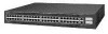
48 32 33 CONSOLE 10MB MGT 34 PWR RESET The Catalyst 2948G, 2948G-GE-TX, and 2980G switches interface with networking equipment using Ethernet (10BASE-T), Fast Ethernet (100BASE-T), and Gigabit Ethernet (1000BASE-T) interfaces. Depending on the model, the switches also support Gigabit Interface - Cisco 2948G | Hardware Installation Guide - Page 31
on page 4-2. For a complete list of supported GBIC modules, see Table 4-1 on page 4-3. Note The Catalyst 2948G-GE-TX switch does not support GBIC modules. The Gigabit Ethernet ports can be configured with any combination of GBIC types. The Gigabit Ethernet ports on these modules are used primarily - Cisco 2948G | Hardware Installation Guide - Page 32
for backbone interconnection of high-performance switches and routers • Layer 2 forwarding with an aggregate forwarding rate of greater than 17.8 million packets per second • 16,000 MAC addresses per system Catalyst 2984G, 2948G-GE-TX, and 2980G Switch Hardware Installation Guide 1-4 78-6286-05 - Cisco 2948G | Hardware Installation Guide - Page 33
RJ-45 10BASE-T console serial port • 10BASE-T out-of-band management and in-band management through any switch port with SNMP, Telnet client, and TFTP Note The Catalyst 2948G-GE-TX and 2980G-A switches have a 10/100BASE-T management port. • RMON4 with RMON 1 • Standard Layer 2 elements: - 802.1D - Cisco 2948G | Hardware Installation Guide - Page 34
Catalyst 2948G switch • 156 W AC internal power supply on the Catalyst 2948G-GE-TX switch • 175 W AC internal power supply on the Catalyst 2980G switch 1. VTP = VLAN Trunking Protocol 2. PAgP = Port Aggregation Protocol 3. CLI = command-line interface 4. RMON = Remote Monitoring 5. CDP = Cisco - Cisco 2948G | Hardware Installation Guide - Page 35
the right of ports 31 and 32. The port on the left is port 33; the port on the right is port 34. The Link Status LEDs for the Gigabit Ethernet ports are located below each port. Catalyst 2948G-GE-TX Switch Ports The Catalyst 2948G-GE-TX 10/100/1000BASE-T Gigabit Ethernet ports are configured in two - Cisco 2948G | Hardware Installation Guide - Page 36
• Airflow, page 9 • Power Supplies, page 11 Management Ports The Catalyst 2948G, 2948G-GE-TX, and 2980G switches have two kinds of management ports: console serial and Ethernet. The Catalyst 2948G switches have a 10BASE-T management port. The Catalyst 2948G-GE-TX and 2980G-A switches have a 10 - Cisco 2948G | Hardware Installation Guide - Page 37
port. No signal detected, or link configuration failure. Indicates power supply operation or failure. Power supply is operational. Power supply has failed or is in Standby mode. Airflow Note For environmental specifications, see Chapter 2, "Site Planning." On the Catalyst 2948G and 2980G switches - Cisco 2948G | Hardware Installation Guide - Page 38
the direction of airflow through the Catalyst 2980G switch. Figure 1-4 Catalyst 2948G Airflow 98432 STATUS Catalyst 2948G CONSOLE 1000Base - X 10BaseT Figure 1-5 Catalyst 2948G-GE-TX Airflow 98720 1-10 Catalyst 2984G, 2948G-GE-TX, and 2980G Switch Hardware Installation Guide 78-6286-05 - Cisco 2948G | Hardware Installation Guide - Page 39
the status using switch software. The switches have the following power supplies: • 120 W AC internal power supply-Catalyst 2948G switch • 156 W AC internal power supply-Catalyst 2948G-GE-TX switch • 175 W AC internal power supply-Catalyst 2980G switch • 156 W AC internal power supply-Catalyst 2980G - Cisco 2948G | Hardware Installation Guide - Page 40
receptacle. Statement 112 • The Catalyst 2948G-GE-TX switch uses the Cisco RPS 675 (model PWR675-AC-RPS-N1). The RPS 675 supports six external network devices and provides DC power to one failed device at a time. It automatically senses when the internal power supply of a connected device fails and - Cisco 2948G | Hardware Installation Guide - Page 41
has status LEDs (PSI, PWR, and RPS). The RPS uses redundant power supplies. If one of the power supplies in the RPS fails, the RPS will automatically switch over to the other power supply without forcing the switch to reboot. Note On the Catalyst 2948G-GE-TX and 2948G switches, only one power source - Cisco 2948G | Hardware Installation Guide - Page 42
Switch Components Chapter 1 Product Overview 1-14 Catalyst 2984G, 2948G-GE-TX, and 2980G Switch Hardware Installation Guide 78-6286-05 - Cisco 2948G | Hardware Installation Guide - Page 43
2980G Switches Only), page 3 • Site-Planning Checklist, page 7 Note See the "Site-Planning Checklist" section on page 7 to help ensure that you complete all site-planning activities before you install the switch. 78-6286-05 Catalyst 2984G, 2948G-GE-TX, and 2980G Switch Hardware Installation Guide - Cisco 2948G | Hardware Installation Guide - Page 44
Note Catalyst 2948G, 2948G-GE-TX, and 2980G switches have internal power supplies. All of the switches support Cisco Redundant Power System (RPS) for redundant operation. This section provides site power requirements and heat dissipation specifications for the Catalyst 2948G, 2948G-GE-TX, and - Cisco 2948G | Hardware Installation Guide - Page 45
power supplies. Note These guidelines do not apply to the Catalyst 2948G-GE-TX switches. See Figure 2-1 for the location of the grounding holes on the Catalyst 2948G switches and Figure 2-2 for the location on the Catalyst 2980G switches. 78-6286-05 Catalyst 2984G, 2948G-GE-TX, and 2980G Switch - Cisco 2948G | Hardware Installation Guide - Page 46
on the location of your switch within the site and its proximity to proper grounding facilities. The grounding wire is not available from Cisco Systems; it is available from any commercial cable vendor. Catalyst 2984G, 2948G-GE-TX, and 2980G Switch Hardware Installation Guide 2-4 78-6286-05 - Cisco 2948G | Hardware Installation Guide - Page 47
to connect the Catalyst 2948G, 2948G-GE-TX, and 2980G switches to earth ground. We strongly recommend that you complete this procedure before connecting system power or turning on your switch. To attach the grounding lug and cable to the grounding pad on the Catalyst 2948G, 2948G-GE-TX, and 2980G - Cisco 2948G | Hardware Installation Guide - Page 48
through the holes in the grounding lug and the grounding pad. Ensure that the grounding lug and the attached wire will not interfere with other switch hardware or rack equipment. Catalyst 2984G, 2948G-GE-TX, and 2980G Switch Hardware Installation Guide 2-6 78-6286-05 - Cisco 2948G | Hardware Installation Guide - Page 49
3 Power evaluation: Input power type Proximity of receptacle to the equipment Dedicated (separate) circuits for redundant power supplies UPS for power failures 4 Grounding evaluation: Circuit breaker size 78-6286-05 Catalyst 2984G, 2948G-GE-TX, and 2980G Switch Hardware Installation Guide 2-7 - Cisco 2948G | Hardware Installation Guide - Page 50
Connector type Cable distance limitations Interface equipment (transceivers) EMI evaluation: Distance limitations for signaling Site wiring RFI levels Chapter 2 Site Planning Verified By Time Date Catalyst 2984G, 2948G-GE-TX, and 2980G Switch Hardware Installation Guide 2-8 78-6286-05 - Cisco 2948G | Hardware Installation Guide - Page 51
Preparing for Installation, page 2 • Installing the Catalyst 2948G and 2980G Switches, page 6 • Installing the Catalyst 2948G-GE-TX Switch, page 9 • Connecting Power to the Switches, page 19 • Connecting a Terminal to the Console Serial and Ethernet Management Ports, page 22 Note Before starting the - Cisco 2948G | Hardware Installation Guide - Page 52
of this manual. Taiwan Warning This is a Class A Information Product, when used in residential environment, it may cause radio frequency interference, under such circumstances, the user may be requested to take appropriate countermeasures. Catalyst 2984G, 2948G-GE-TX, and 2980G Switch Hardware - Cisco 2948G | Hardware Installation Guide - Page 53
this equipment is used in a domestic environment, radio disturbance may arise. When such trouble occurs, the user may be required to take corrective actions. Korea Warning This with a residential-use type. 78-6286-05 Catalyst 2984G, 2948G-GE-TX, and 2980G Switch Hardware Installation Guide 3-3 - Cisco 2948G | Hardware Installation Guide - Page 54
all listed equipment. Catalyst 2948G and 2980G Switches The Catalyst 2948G and 2980G switches are shipped with these items: • This hardware guide • AC power cord • RJ-45 to DB-9 cable • DB-9 to RJ-45 cable Catalyst 2984G, 2948G-GE-TX, and 2980G Switch Hardware Installation Guide 3-4 78-6286-05 - Cisco 2948G | Hardware Installation Guide - Page 55
Preparing for Installation • ESD wrist strap • Mounting kit Catalyst 2948G-GE-TX Switches The Catalyst 2948G-GE-TX switch is shipped with these items: • This hardware guide • About the Catalyst 2948G Documentation flyer • AC power cord • One RJ-45-to-DB-9 adapter cable (78-3383-XX) • Mounting - Cisco 2948G | Hardware Installation Guide - Page 56
foam • Your own electrostatic discharge (ESD) grounding strap or the disposable ESD strap included with the switch Note For more information about ESD, refer to the Site Preparation and Safety Guide. Catalyst 2984G, 2948G-GE-TX, and 2980G Switch Hardware Installation Guide 3-6 78-6286-05 - Cisco 2948G | Hardware Installation Guide - Page 57
24 x 3/4-inch Phillips binder-head screws Quantity 2 4 6 Note Some equipment racks have a power strip along the length of one of the rear posts. If the rack has this feature, rack-mount kit (see Figure 3-1). 78-6286-05 Catalyst 2984G, 2948G-GE-TX, and 2980G Switch Hardware Installation Guide 3-7 - Cisco 2948G | Hardware Installation Guide - Page 58
and into the threaded holes in the mounting post. d. Use the tape measure and level to ensure that the chassis is installed straight and level. Catalyst 2984G, 2948G-GE-TX, and 2980G Switch Hardware Installation Guide 3-8 78-6286-05 - Cisco 2948G | Hardware Installation Guide - Page 59
the Rack 17.75 inches (45.09 cm) STATUS Catalyst 2948G CONSOLE 1000Base - X 10BaseT Installing the Catalyst 2948G-GE-TX Switch 98436 Installing the Catalyst 2948G-GE-TX Switch Warning To prevent bodily injury when mounting or servicing this unit in a rack, you must take special precautions - Cisco 2948G | Hardware Installation Guide - Page 60
the Catalyst 2948G-GE-TX Switch, page 16 • Mounting the Catalyst 2948G-GE-TX Switch on a Table or Shelf, page 19 Rack-Mounting the Catalyst 2948G-GE-TX Switch To install a Catalyst 2948G-GE-TX switch in a 19-inch rack (24-inch racks require optional mounting hardware), follow the instructions - Cisco 2948G | Hardware Installation Guide - Page 61
-1RU=) from Cisco. Figure 3-4 through Figure 3-9 show how to attach each type of bracket to one side of the switch. Follow the same steps to attach the second bracket to the opposite side of the switch. 78-6286-05 Catalyst 2984G, 2948G-GE-TX, and 2980G Switch Hardware Installation Guide 3-11 - Cisco 2948G | Hardware Installation Guide - Page 62
Racks, Front Panel Forward 1 98660 98657 1 Phillips flat-head screws Figure 3-5 Attaching Brackets for 19-Inch Racks, Rear Panel Forward 1 1 Phillips flat-head screws 3-12 Catalyst 2984G, 2948G-GE-TX, and 2980G Switch Hardware Installation Guide 78-6286-05 - Cisco 2948G | Hardware Installation Guide - Page 63
Panel Forward 1 98661 98662 1 Phillips flat-head screws Figure 3-7 Attaching Brackets for 24-Inch Racks, Rear Panel Forward 1 1 Phillips flat-head screws 78-6286-05 Catalyst 2984G, 2948G-GE-TX, and 2980G Switch Hardware Installation Guide 3-13 - Cisco 2948G | Hardware Installation Guide - Page 64
Mounting the Switch in a Rack After the brackets are attached to the switch, use the four supplied number-12 Phillips machine screws to securely attach the brackets to the rack, as shown in Figure 3-10. 98664 3-14 Catalyst 2984G, 2948G-GE-TX, and 2980G Switch Hardware Installation Guide 78-6286 - Cisco 2948G | Hardware Installation Guide - Page 65
right bracket. Figure 3-11 Attaching the Cable Guide on the Catalyst 2948G-GE-TX Switch 1 1 Cable guide screw Note The Catalyst 2948G-GE-TX switch ships with a special cable guide, as shown in Figure 3-11. This cable guide secures up to 48 cables. Use the supplied black screw to mount it on the - Cisco 2948G | Hardware Installation Guide - Page 66
Installing the Catalyst 2948G-GE-TX Switch Chapter 3 Installing the Switch Wall-Mounting the Catalyst 2948G-GE-TX Switch To install the Catalyst 2948G-GE-TX switch on a wall, follow the instructions in these procedures: • Attaching the Brackets to the Switch for Wall-Mounting, page 16 • Attaching - Cisco 2948G | Hardware Installation Guide - Page 67
Cover on the Catalyst 2948G-GE-TX Switch 1.6A-100R>09A-A2T0,IN05GV0-~60 HZ [email protected] 98668 1 2 3 1 Phillips pan-head screws 2 RPS connector cover 3 RPS connector Mounting the Switch on a Wall For the best support of the switch and cables, make - Cisco 2948G | Hardware Installation Guide - Page 68
the Switch Warning To comply with safety regulations, mount the switches on a wall with the front panel facing up. Statement 266 Figure 3-14 Mounting the Switch on a Wall 1 1 98669 1 User-supplied screws 3-18 Catalyst 2984G, 2948G-GE-TX, and 2980G Switch Hardware Installation Guide 78 - Cisco 2948G | Hardware Installation Guide - Page 69
, the LED is amber. From the system console, enter the show system command to display the power supply and system status. For more information on commands, refer to the command reference for your switch. 78-6286-05 Catalyst 2984G, 2948G-GE-TX, and 2980G Switch Hardware Installation Guide 3-19 - Cisco 2948G | Hardware Installation Guide - Page 70
system command indicate a power problem or other system problem, see Appendix D, "Translated Safety Warnings" for more information. Connecting to 10/100 and 10/100/1000 Ports The 10/100 ports on the Catalyst 2948G and 2980G switches configure themselves to operate at the speed and duplex settings - Cisco 2948G | Hardware Installation Guide - Page 71
use a four twisted-pair, Category 5 cable. Figure 3-15 Connecting to a 10/100 or 10/100/1000 Port 98654 STATUS Catalyst 2948G Step 2 Insert the other cable end in an RJ-45 connector on the target device. 78-6286-05 Catalyst 2984G, 2948G-GE-TX, and 2980G Switch Hardware Installation Guide 3-21 - Cisco 2948G | Hardware Installation Guide - Page 72
. Repeat Steps 1 through 4 to connect each port. Connecting a Terminal to the Console Serial and Ethernet Management Ports The console serial and Ethernet management ports are located on the front panel of the Catalyst 2948G, 2948G-GE-TX, and 2980G switches. These ports use an RJ-45 media-dependent - Cisco 2948G | Hardware Installation Guide - Page 73
engine begins to initialize the interfaces. During this initialization, the interface LEDs flash on and off. When initialization is complete, the console screen displays a script and system banner. 78-6286-05 Catalyst 2984G, 2948G-GE-TX, and 2980G Switch Hardware Installation Guide 3-23 - Cisco 2948G | Hardware Installation Guide - Page 74
system startup, they do not indicate an accurate status until the interface is configured. Note If the system does not complete this verification process, see Chapter 5, "Troubleshooting the Installation." 3-24 Catalyst 2984G, 2948G-GE-TX, and 2980G Switch Hardware Installation Guide 78-6286-05 - Cisco 2948G | Hardware Installation Guide - Page 75
Ethernet ports can be configured with any combination of GBICs. The Gigabit Ethernet ports on these modules are used primarily for backbone interconnection of other high-performance switches and routers. 78-6286-05 Catalyst 2984G, 2948G-GE-TX, and 2980G Switch Hardware Installation Guide 4-1 - Cisco 2948G | Hardware Installation Guide - Page 76
, linking the module with a fiber-optic network. The GBICs use SC-type connectors and plug into connectors on the module. You can install any combination of GBICs in the Gigabit Ethernet switching module. Catalyst 2984G, 2948G-GE-TX, and 2980G Switch Hardware Installation Guide 4-2 78-6286-05 - Cisco 2948G | Hardware Installation Guide - Page 77
quality allows them to reach 10 kilometers over single-mode fiber (SMF) versus the 5 kilometers specified in the standard. Other GBIC media types may be supported as additional technology becomes available. 78-6286-05 Catalyst 2984G, 2948G-GE-TX, and 2980G Switch Hardware Installation Guide 4-3 - Cisco 2948G | Hardware Installation Guide - Page 78
km) 62.1 mi (100 km) 1. Nominal fiber specification wavelength. 2. MMF only. 3. Patch cord required (refer to the "Patch Cord" section on page 4-10 for details). 4. Dispersion-shifted single-mode fiber-optic. Catalyst 2984G, 2948G-GE-TX, and 2980G Switch Hardware Installation Guide 4-4 78-6286-05 - Cisco 2948G | Hardware Installation Guide - Page 79
cabling restrictions when using GBICs: • The minimum cabling distance for 1000BASE-SX and 1000BASE-LX/LH GBICs is 6.5 feet (2 meters). • The maximum cabling distance for each GBIC type is listed in Table 4-2. 78-6286-05 Catalyst 2984G, 2948G-GE-TX, and 2980G Switch Hardware Installation Guide 4-5 - Cisco 2948G | Hardware Installation Guide - Page 80
or inserting a GBIC, always wear an ESD wrist strap connected to the ESD wrist strap connector. For more information about ESD, refer to the Site Preparation and Safety Guide. Note GBICs are online swappable. Catalyst 2984G, 2948G-GE-TX, and 2980G Switch Hardware Installation Guide 4-6 78-6286 - Cisco 2948G | Hardware Installation Guide - Page 81
switch. Note GBICs are keyed to prevent incorrect slot insertion. See Figure 4-4. Figure 4-2 Installing a GBIC on a Catalyst 2948G Switch 98456 STATUS Catalyst 2948G CONSOLE 1000Base - X 10BaseT Plug GBIC 78-6286-05 Catalyst 2984G, 2948G-GE-TX, and 2980G Switch Hardware Installation Guide - Cisco 2948G | Hardware Installation Guide - Page 82
if necessary. Insert the connector into the GBIC. When you plug the SC-type connector into the GBIC, make sure that both the Tx and Rx fiber-optic cables are already fully inserted into the SC-type connector. Catalyst 2984G, 2948G-GE-TX, and 2980G Switch Hardware Installation Guide 4-8 78-6286-05 - Cisco 2948G | Hardware Installation Guide - Page 83
these steps: Step 1 Step 2 Disconnect the fiber-optic cable from the GBIC SC-type connector. Release the GBIC from the slot by simultaneously squeezing the plastic tabs (one on each side of the GBIC). 78-6286-05 Catalyst 2984G, 2948G-GE-TX, and 2980G Switch Hardware Installation Guide 4-9 - Cisco 2948G | Hardware Installation Guide - Page 84
types of fiber-optic cable due to a problem in the center of some fiber-optic cable cores. The solution is to launch light from the laser at a precise offset from the center by using the patch cord. At 4-10 Catalyst 2984G, 2948G-GE-TX, and 2980G Switch Hardware Installation Guide 78-6286-05 - Cisco 2948G | Hardware Installation Guide - Page 85
"To equipment" into the GBIC (see Figure 4-6). Plug the end labeled "To cable plant" into the patch panel. The patch cord is 9.84 feet (3 meters) long and has duplex SC-type male connectors at each end. 78-6286-05 Catalyst 2984G, 2948G-GE-TX, and 2980G Switch Hardware Installation Guide 4-11 - Cisco 2948G | Hardware Installation Guide - Page 86
Pluggable Modules Installation Notes (not orderable but is available on Cisco.com) and to the documentation that came with your SFP module. Table 4-4 lists the SFP modules supported by the Catalyst 2948G-GE-TX switch. Table 4-4 Supported SFP Modules SFP Type Fiber-optic 1000BASE-LX Fiber-optic - Cisco 2948G | Hardware Installation Guide - Page 87
Multiplexing (CWDM), refer to the Cisco CWDM GBIC and CWDM SFP Installation Note. The 1000BASE-T (copper) SFP module is used to establish a Gigabit Ethernet connection through a Category 5 Category 5 cable. Use only Cisco SFP modules on the Catalyst 2948G-GE-TX switch. Each SFP module has an - Cisco 2948G | Hardware Installation Guide - Page 88
Step 1 Step 2 Remove the rubber plugs from the module port and fiber-optic cable, and store them for future use. Insert one end of the fiber-optic cable into the SFP module port, as shown in Figure 4-7. 4-14 Catalyst 2984G, 2948G-GE-TX, and 2980G Switch Hardware Installation Guide 78-6286-05 - Cisco 2948G | Hardware Installation Guide - Page 89
be turned on, there might be a cable problem, or there might be problem with the adapter installed in the target device. See Chapter 5, "Troubleshooting the Installation," for solutions to cabling problems. 78-6286-05 Catalyst 2984G, 2948G-GE-TX, and 2980G Switch Hardware Installation Guide 4-15 - Cisco 2948G | Hardware Installation Guide - Page 90
. After you have connected all the interfaces, check all connections, and then perform the steps described in the "Verifying Switch Operation" section on page 3-23 to verify that the switch is operational. 4-16 Catalyst 2984G, 2948G-GE-TX, and 2980G Switch Hardware Installation Guide 78-6286-05 - Cisco 2948G | Hardware Installation Guide - Page 91
functions are included in the following sections because they also monitor DC-line voltages. For configuration questions or problems, refer to the software configuration guide or the command reference for your switch. 78-6286-05 Catalyst 2984G, 2948G-GE-TX, and 2980G Switch Hardware Installation - Cisco 2948G | Hardware Installation Guide - Page 92
assembly is operating. • On Catalyst 2948G-GE-TX switches, the blower is operating. If all of these conditions are met and the hardware installation is complete, refer to the software configuration guide and the command reference for your switch to troubleshoot the software. However, if any of these - Cisco 2948G | Hardware Installation Guide - Page 93
the port is bad. Note After the diagnostic boot tests, the single flash of amber on the Link LED may occur too quickly to be detected visually. • If a STATUS LED is red or amber, contact a customer service representative for instructions. 78-6286-05 Catalyst 2984G, 2948G-GE-TX, and 2980G Switch - Cisco 2948G | Hardware Installation Guide - Page 94
power supply. Note If the power supply is a Cisco RPS 675 and the LED is amber, the RPS may be in standby mode. Press the Standby/Active button on the RPS to put it in active mode and the LED should then turn to green. Catalyst 2984G, 2948G-GE-TX, and 2980G Switch Hardware Installation Guide - Cisco 2948G | Hardware Installation Guide - Page 95
Type of software and release number • Maintenance agreement or warranty information • Brief description of the problem • Brief explanation of the steps you have already taken to isolate and resolve the problem 78-6286-05 Catalyst 2984G, 2948G-GE-TX, and 2980G Switch Hardware Installation Guide 5-5 - Cisco 2948G | Hardware Installation Guide - Page 96
Contacting Customer Service Chapter 5 Troubleshooting the Installation Catalyst 2984G, 2948G-GE-TX, and 2980G Switch Hardware Installation Guide 5-6 78-6286-05 - Cisco 2948G | Hardware Installation Guide - Page 97
appendix provides management port and technical specifications for the Catalyst 2948G, 2948G-GE-TX, and 2980G switches. Console Serial Port The console serial port is an RJ-45 receptacle. Data terminal ready (DTR) and data set ready (DSR) handshake signals are supported on this port. The Request - Cisco 2948G | Hardware Installation Guide - Page 98
Link Status LED. Table A-2 lists the port pinouts. Table A-2 10BASE-T Port Pinouts Pin Signal 1 RXD+ 2 RXD3 TXD+ 4 unused 5 unused 6 TXD7 unused 8 unused Direction input input output Description receive data receive data transmit data output transmit data Catalyst 2948G Switch Specifications - Cisco 2948G | Hardware Installation Guide - Page 99
W 645 BTU/hr. 2.5 A maximum at 100 VAC 1.3 A maximum at @ 240 VAC 50 to 60 Hz 0.20 Front side in, back side out 78-6286-05 Catalyst 2984G, 2948G-GE-TX, and 2980G Switch Hardware Installation Guide A-3 - Cisco 2948G | Hardware Installation Guide - Page 100
Regulations 7. ICES = International Commerce Exchange Systems 8. CISPR = Comite International Special des Perturbation Radioelectriques 9. VCCI = Voluntary Control Council for Information Technology Equipment Catalyst 2984G, 2948G-GE-TX, and 2980G Switch Hardware Installation Guide A-4 78-6286-05 - Cisco 2948G | Hardware Installation Guide - Page 101
W x D) Weight AC Power Power supply output System power dissipation System heat dissipation AC input current AC frequency KVA rating Airflow Specification 32°F (0°C) to 104°F 0.13 Front side in, back side out 78-6286-05 Catalyst 2984G, 2948G-GE-TX, and 2980G Switch Hardware Installation Guide A-5 - Cisco 2948G | Hardware Installation Guide - Page 102
. Table A-5 Catalyst 2980G Switch Specifications Item Environmental Temperature, ambient operating Temperature, ambient nonoperating and storage Specification 32°F (0°C) to 104°F (40°C) -4°F (-20°C) to 149°F (65°C) Catalyst 2984G, 2948G-GE-TX, and 2980G Switch Hardware Installation Guide A-6 78 - Cisco 2948G | Hardware Installation Guide - Page 103
Catalyst 2980G-A) AC input current 3 A maximum at 100 VAC 1 A maximum at 240 VAC AC frequency 50 to 60 Hz KVA rating 0.30 Airflow Right side in, left side out Standards Compliance Compliance CE Marking 78-6286-05 Catalyst 2984G, 2948G-GE-TX, and 2980G Switch Hardware Installation Guide - Cisco 2948G | Hardware Installation Guide - Page 104
Commerce Exchange Systems 9. CISPR = Comite International Special des Perturbation Radioelectriques 10. VCCI = Voluntary Control Council for Information Technology Equipment 11. FTP = foil-twisted pair Catalyst 2984G, 2948G-GE-TX, and 2980G Switch Hardware Installation Guide A-8 78-6286-05 - Cisco 2948G | Hardware Installation Guide - Page 105
This appendix provides repacking and shipping instructions for the Catalyst 2948G, 2948G-GE-TX, and 2980G switches if you need to return your switch to the factory. To repack the switch using the original packaging material, follow these steps: Step 1 Slide the pieces of the packing foam over - Cisco 2948G | Hardware Installation Guide - Page 106
Figure B-1 Switch Packing Material Packing foam SCTaAtaTlyUsSt 2948G Appendix B Repacking a Switch Documentation and accessories in poly bag Packing foam CONSOLE 1000Base - X 10BaseT Packing carton 29715 Catalyst 2984G, 2948G-GE-TX, and 2980G Switch Hardware Installation Guide B-2 78-6286- - Cisco 2948G | Hardware Installation Guide - Page 107
become two independent pulses. Strings of pulses tend to interfere with each other, making it difficult to recover data in a reliable fashion. 78-6286-05 Catalyst 2984G, 2948G-GE-TX, and 2980G Switch Hardware Installation Guide C-1 - Cisco 2948G | Hardware Installation Guide - Page 108
launch look more like an LED source to the cable. The objective is to scramble the modes of light to distribute the power more equally in all modes and prevent the light from being concentrated in just a few Catalyst 2984G, 2948G-GE-TX, and 2980G Switch Hardware Installation Guide C-2 78-6286-05 - Cisco 2948G | Hardware Installation Guide - Page 109
mode-conditioning patch cord for all interfaces using MMF when the link span exceeds 984 feet (300 meters). For link spans less than this, you can omit the patch cord (there is no problem using it on short links). 78-6286-05 Catalyst 2984G, 2948G-GE-TX, and 2980G Switch Hardware Installation Guide - Cisco 2948G | Hardware Installation Guide - Page 110
Appendix C Differential Mode Delay Catalyst 2984G, 2948G-GE-TX, and 2980G Switch Hardware Installation Guide C-4 78-6286-05 - Cisco 2948G | Hardware Installation Guide - Page 111
D A P P E N D I X Translated Safety Warnings This appendix repeats in multiple languages the warnings in this guide. These translated warnings can be used with other documents related to this guide. 78-6286-05 Catalyst 2984G, 2948G-GE-TX, and 2980G Switch Hardware Installation Guide D-1 - Cisco 2948G | Hardware Installation Guide - Page 112
warnings that accompanied this device. Statement 1071 SAVE THESE INSTRUCTIONS Waarschuwing BELANGRIJKE VEILIGHEIDSINSTRUCTIES Dit waarschuwingssymbool betekent gevaar. U verkeert avulla. SÄILYTÄ NÄMÄ OHJEET Catalyst 2984G, 2948G-GE-TX, and 2980G Switch Hardware Installation Guide D-2 78-6286-05 - Cisco 2948G | Hardware Installation Guide - Page 113
traduites qui accompagnent cet appareil, référez-vous au numéro de l'instruction situé à la fin de chaque avertissement. CONSERVEZ CES INFORMATIONS Warnung WICHTIGE documento. CONSERVARE QUESTE ISTRUZIONI 78-6286-05 Catalyst 2984G, 2948G-GE-TX, and 2980G Switch Hardware Installation Guide D-3 - Cisco 2948G | Hardware Installation Guide - Page 114
da instrução fornecido ao final de cada aviso para localizar sua tradução nos avisos de segurança traduzidos que acompanham este dispositivo. GUARDE ESTAS INSTRUÇÕES Catalyst 2984G, 2948G-GE-TX, and 2980G Switch Hardware Installation Guide D-4 78-6286-05 - Cisco 2948G | Hardware Installation Guide - Page 115
som finns i slutet av varje varning för att hitta dess översättning i de översatta säkerhetsvarningar som medföljer denna anordning. SPARA DESSA ANVISNINGAR 78-6286-05 Catalyst 2984G, 2948G-GE-TX, and 2980G Switch Hardware Installation Guide D-5 - Cisco 2948G | Hardware Installation Guide - Page 116
Warning Definition Appendix D Translated Safety Warnings Catalyst 2984G, 2948G-GE-TX, and 2980G Switch Hardware Installation Guide D-6 78-6286-05 - Cisco 2948G | Hardware Installation Guide - Page 117
Before you install, operate, or service the system, read the Site Preparation and Safety Guide. This guide contains important safety information you should know zijn voordat u met het systeem gaat werken. 78-6286-05 Catalyst 2984G, 2948G-GE-TX, and 2980G Switch Hardware Installation Guide D-7 - Cisco 2948G | Hardware Installation Guide - Page 118
installerar, använder eller utför service på systemet ska du läsa Förberedelser och säkerhet Handbok. Denna handbok innehåller viktig säkerhetsinformation som du bör känna till innan du arbetar med systemet. Catalyst 2984G, 2948G-GE-TX, and 2980G Switch Hardware Installation Guide D-8 78-6286-05 - Cisco 2948G | Hardware Installation Guide - Page 119
y reemplazados exclusivamente por personal técnico adecuadamente preparado y capacitado. Varning Denna utrustning ska endast installeras och bytas ut av utbildad och kvalificerad personal. 78-6286-05 Catalyst 2984G, 2948G-GE-TX, and 2980G Switch Hardware Installation Guide D-9 - Cisco 2948G | Hardware Installation Guide - Page 120
tre émis par l'ouverture du port quand aucun câble n'est Ports kann unsichtbare Laserstrahlung austreten, wenn kein Kabel angeschlossen ist. Kontakt mit Laserstrahlung vermeiden und nicht in offene Öffnungen blicken. D-10 Catalyst 2984G, 2948G-GE-TX, and 2980G Switch Hardware Installation Guide - Cisco 2948G | Hardware Installation Guide - Page 121
invisibile, evitare l'esposizione a tale radiazione e non fissare con gli occhi porte a cui non siano collegati cavi. Advarsel Usynlige laserstråler kan sendes ut katso niitä suoraan optisilla välineillä. 78-6286-05 Catalyst 2984G, 2948G-GE-TX, and 2980G Switch Hardware Installation Guide D-11 - Cisco 2948G | Hardware Installation Guide - Page 122
avges från frånkopplade fibrer eller kontaktdon. Rikta inte blicken in i strålar och titta aldrig direkt på dem med hjälp av optiska instrument. D-12 Catalyst 2984G, 2948G-GE-TX, and 2980G Switch Hardware Installation Guide 78-6286-05 - Cisco 2948G | Hardware Installation Guide - Page 123
(modell PWR300-AC-RPS-N1) til RPS-stikkontakten. Aviso Anexe o RPS Cisco (modelo PWR300-AC-RPS-N1) apenas ao receptáculo RPS. ¡Advertencia! Sólo conecte el Cisco RPS (modelo PWR300-AC-RPS-N1) al receptáculo RPS. 78-6286-05 Catalyst 2984G, 2948G-GE-TX, and 2980G Switch Hardware Installation Guide - Cisco 2948G | Hardware Installation Guide - Page 124
au connecteur RPS. Warnung An die RPS-Steckhülse darf nur das Cisco RPS (Modell PWR600-AC-RPS) angeschlossen werden. Avvertenza Collegare soltanto il Cisco RPS (modello PWR600-AC-RPS) alla presa RPS. D-14 Catalyst 2984G, 2948G-GE-TX, and 2980G Switch Hardware Installation Guide 78-6286-05 - Cisco 2948G | Hardware Installation Guide - Page 125
RPS receptacle. Statement 100C Waarschuwing Slechts de Cisco RPS (model PWR675-AC-RPS-N1) aan de RPS contactdoos verbinden. Varoitus Kiinnitä RPS-vastakappaleeseen vain Cisco RPS (malli PWR675-AC-RPS-N1). 78-6286-05 Catalyst 2984G, 2948G-GE-TX, and 2980G Switch Hardware Installation Guide D-15 - Cisco 2948G | Hardware Installation Guide - Page 126
-AC-RPS-N1) apenas ao receptáculo RPS. ¡Advertencia! Sólo conecte el Cisco RPS (modelo PWR675-AC-RPS-N1) al receptáculo RPS. Varning! Koppla endast Ciscos RPS (modell PWR675-AC-RPS-N1) till RPS-uttaget. D-16 Catalyst 2984G, 2948G-GE-TX, and 2980G Switch Hardware Installation Guide 78-6286-05 - Cisco 2948G | Hardware Installation Guide - Page 127
de conector RPS na parte de trás do switch. ¡Advertencia! Si no se conecta un sistema de potencia redundante (RPS) al interruptor, instale una cubierta de conector RPS en la parte posterior del interruptor. 78-6286-05 Catalyst 2984G, 2948G-GE-TX, and 2980G Switch Hardware Installation Guide D-17 - Cisco 2948G | Hardware Installation Guide - Page 128
power system, RPS) inte finns anslutet till switchen skall ett RPS-kontaktskydd installeras på switchens baksida. Switch Installation Warning Warning To comply with safety regulations, mount switches haut. D-18 Catalyst 2984G, 2948G-GE-TX, and 2980G Switch Hardware Installation Guide 78-6286-05 - Cisco 2948G | Hardware Installation Guide - Page 129
opp. Aviso Para cumprir com os regulamentos de segurança, faça a montagem de switches em uma parede com o painel frontal virado para cima. ¡Advertencia! Para cumplir en vägg med frampanelen riktad uppåt. 78-6286-05 Catalyst 2984G, 2948G-GE-TX, and 2980G Switch Hardware Installation Guide D-19 - Cisco 2948G | Hardware Installation Guide - Page 130
rack is provided with stabilizing devices, install the stabilizers before mounting or servicing the unit in the rack. Statement 1006 Waarschuwing Om lichamelijk letsel te voorkomen sen huoltamista siinä. D-20 Catalyst 2984G, 2948G-GE-TX, and 2980G Switch Hardware Installation Guide 78-6286-05 - Cisco 2948G | Hardware Installation Guide - Page 131
D Translated Safety Warnings Chassis Warning for Rack-Mounting and Servicing Attention Pour éviter toute blessure corporelle pendant les opérations o di procedere alla manutenzione dell'unità nel supporto. 78-6286-05 Catalyst 2984G, 2948G-GE-TX, and 2980G Switch Hardware Installation Guide D-21 - Cisco 2948G | Hardware Installation Guide - Page 132
Chassis Warning for Rack-Mounting and Servicing Appendix D Translated Safety Warnings Advarsel Unngå fysiske skader under montering eller al mantenimiento del equipo instalado en el bastidor. D-22 Catalyst 2984G, 2948G-GE-TX, and 2980G Switch Hardware Installation Guide 78-6286-05 - Cisco 2948G | Hardware Installation Guide - Page 133
Appendix D Translated Safety Warnings Chassis Warning for Rack-Mounting and Servicing Varning! För att undvika kroppsskada när du installerar eller utför underh eller underhålls på ställningen. • • • 78-6286-05 Catalyst 2984G, 2948G-GE-TX, and 2980G Switch Hardware Installation Guide D-23 - Cisco 2948G | Hardware Installation Guide - Page 134
Chassis Warning for Rack-Mounting and Servicing • • • • • • Appendix D Translated Safety Warnings D-24 Catalyst 2984G, 2948G-GE-TX, and 2980G Switch Hardware Installation Guide 78-6286-05 - Cisco 2948G | Hardware Installation Guide - Page 135
4-3, 4-11 A airflow 1-9 to 1-11 attaching the cable guide 3-15 autonegotiation 1-4 B BER 4-10 bit error rate See BER blower see airflow boot process observing LEDs 3-23 brackets See mounting brackets 78-6286-05 Catalyst 2984G, 2948G-GE-TX, and 2980G Switch Hardware Installation Guide IN-1 - Cisco 2948G | Hardware Installation Guide - Page 136
(Catalyst 2948G and 2980G switches) 3-4 shipping container contents (Catalyst 2948G-GE-TX) 3-5 checklist rack-mount 3-7 site planning 2-7 Cisco Discovery Protocol See CDP Cisco Group Management Protocol See CGMP CLI 1-5 command-line interface See CLI commands show port 4-9 configuration, patch - Cisco 2948G | Hardware Installation Guide - Page 137
interfaces 1-2 features 4-2 installing 4-6 maintenance guidelines 4-6, 4-8, 4-9 to 4-10 optical power 4-5 patch cord 4-10 port configuration 4-1 removing 4-9 speeds 1-2 Gigabit Interface Converter See GBICs 78-6286-05 Catalyst 2984G, 2948G-GE-TX, and 2980G Switch Hardware Installation Guide IN-3 - Cisco 2948G | Hardware Installation Guide - Page 138
shelf-mounting Catalyst 2948G-GE-TX switch 3-19 troubleshooting 5-1 wall-mounting 3-16 Catalyst 2948G-GE-TX switch 3-16 to 3-18 invisible radiation warning D-10 to D-11 L laser radiation warning D-11 to D-13 laser transmission C-1 Layer 2 forwarding 1-4 LEDs Link Status 1-8, A-2 power supply 3-19 - Cisco 2948G | Hardware Installation Guide - Page 139
2980G switch A-7 troubleshooting 5-2 power supplies connecting system ground 2-3 description 1-11 internal 1-11 LEDs 5-3 RPS 1-11 RPS 300 1-12 RPS 600 1-12 RPS 675 1-12 supported 1-6 troubleshooting 5-2, 5-3, 5-4 78-6286-05 Catalyst 2984G, 2948G-GE-TX, and 2980G Switch Hardware Installation Guide - Cisco 2948G | Hardware Installation Guide - Page 140
switches 3-7 to 3-9 Catalyst 2948G-GE-TX switch 3-10 to 3-15 rack-mounting kit 3-7 rack-mounting warning D-20 to D-24 Redundant Power System See RPS regulatory statements, EMC 3-2 to 3-4 Remote Monitoring See RMON repacking instructions B-1 returns B-1 RMON 1-5, 1-6 RPS 1-11, 5-4 See power supplies - Cisco 2948G | Hardware Installation Guide - Page 141
service 5-5 getting started 5-2 identifying startup problems 5-3 initial boot 5-2 methodology 5-2 power supplies 5-2, 5-3, 5-4 V verifying switch operation 3-23 virtual LANs See VLANs Virtual Terminal Protocol See VTP (Virtual Terminal Protocol) VLANs 1-5 78-6286-05 Catalyst 2984G, 2948G-GE-TX - Cisco 2948G | Hardware Installation Guide - Page 142
Protocol) VTP (Virtual Terminal Protocol) 1-5 VTP (VLAN Trunk Protocol) 1-5 W wall-mounting 3-16 warning switch installation D-18 to D-19 weight, chassis Catalyst 2948G A-3 Catalyst 2948G-GE-TX A-5 Catalyst 2980G A-7 IN-8 Catalyst 2984G, 2948G-GE-TX, and 2980G Switch Hardware Installation Guide
-
 1
1 -
 2
2 -
 3
3 -
 4
4 -
 5
5 -
 6
6 -
 7
7 -
8
-
9
-
10
-
11
-
12
-
13
-
14
-
15
-
16
-
17
-
18
-
19
-
20
-
21
-
22
-
23
-
24
-
25
-
26
-
27
-
28
-
29
-
30
-
31
-
32
-
33
-
34
-
35
-
36
-
37
-
38
-
39
-
40
-
41
-
42
-
43
-
44
-
45
-
46
-
47
-
48
-
49
-
50
-
51
-
52
-
53
-
54
-
55
-
56
-
57
-
58
-
59
-
60
-
61
-
62
-
63
-
64
-
65
-
66
-
67
-
68
-
69
-
70
-
71
-
72
-
73
-
74
-
75
-
76
-
77
-
78
-
79
-
80
-
81
-
82
-
83
-
84
-
85
-
86
-
87
-
88
-
89
-
90
-
91
-
92
-
93
-
94
-
95
-
96
-
97
-
98
-
99
-
100
-
101
-
102
-
103
-
104
-
105
-
106
-
107
-
108
-
109
-
110
-
111
-
112
-
113
-
114
-
115
-
116
-
117
-
118
-
119
-
120
-
121
-
122
-
123
-
124
-
125
-
126
-
127
-
128
-
129
-
130
-
131
-
132
-
133
-
134
-
135
-
136
-
137
-
138
-
139
-
140
-
141
-
142
 |
 |
Corporate Headquarters
Cisco Systems, Inc.
170 West Tasman Drive
San Jose, CA 95134-1706
USA
Tel:
408 526-4000
800 553-NETS (6387)
Fax:
408 526-4100
Catalyst 2984G, 2948G-GE-TX,
and 2980G Switch Hardware
Installation Guide
October 2003
Customer Order Number: DOC-786286=
Text Part Number: 78-6286-05