Cisco 3550 48 Installation Guide
Cisco 3550 48 - Catalyst SMI Switch Manual
 |
UPC - 746320774053
View all Cisco 3550 48 manuals
Add to My Manuals
Save this manual to your list of manuals |
Cisco 3550 48 manual content summary:
- Cisco 3550 48 | Installation Guide - Page 1
Catalyst 3500 Series XL Hardware Installation Guide August 2003 Corporate Headquarters Cisco Systems, Inc. 170 West Tasman Drive San Jose, CA 95134-1706 USA http://www.cisco.com Tel: 408 526-4000 800 553-NETS (6387) Fax: 408 526-4100 Customer Order Number: DOC-786456= Text Part Number: 78-6456-04 - Cisco 3550 48 | Installation Guide - Page 2
in accordance with the instruction manual, may cause harmful Cisco's installation instructions, it may cause interference with radio and television reception. This equipment has been tested and found to comply with the limits for a Class B digital device in accordance with the specifications - Cisco 3550 48 | Installation Guide - Page 3
, the Cisco Arrow logo, the Cisco Powered Network mark, Cisco Unity, Follow Me Browsing, FormShare, and StackWise are trademarks of Cisco Systems, Inc.; Changing the Way We Work, Live, Play, and Learn, and iQuick Study are service marks of Cisco Systems, Inc.; and Aironet, ASIST, BPX, Catalyst, CCDA - Cisco 3550 48 | Installation Guide - Page 4
- Cisco 3550 48 | Installation Guide - Page 5
Cisco TAC Website xx Opening a TAC Case xxi TAC Case Priority Definitions xxi Obtaining Additional Publications and Information xxii Product Overview 1-1 Features 1-1 Front-Panel Description 1-5 10/100 Ports 1-7 GBIC Module Slots 1-9 78-6456-03 Catalyst 3500 Series XL Hardware Installation Guide - Cisco 3550 48 | Installation Guide - Page 6
LEDs and Modes 1-16 Rear-Panel Description 1-21 Power Connectors 1-22 Internal Power Supply Connector 1-23 Cisco RPS Connector 1-23 Console Port 1-24 Management Options 1-24 Network Configuration Examples 1-25 Design Concepts for Using the Switch 1-25 Small- to Medium-Sized Network Configuration - Cisco 3550 48 | Installation Guide - Page 7
Port 2-23 Assigning Switch Information 2-24 Using the Setup Program 2-25 Using BOOTP 2-29 Default Configuration Settings 2-29 Where to Go Next 2-31 Troubleshooting 3-1 Understanding POST Results 3-2 Diagnosing Problems 3-3 Contents 78-6456-03 Catalyst 3500 Series XL Hardware Installation Guide - Cisco 3550 48 | Installation Guide - Page 8
Attaching the Cisco RPS (model PWR300-AC-RPS-N1) C-4 Service Personnel Warning C-5 Qualified Personnel Warning C-7 Installation Instructions Warning C-9 Jewelry Removal Warning C-10 Stacking the Chassis Warning C-13 Main Disconnecting Device C-15 Overtemperature Warning C-16 TN Power Warning C-19 - Cisco 3550 48 | Installation Guide - Page 9
On/Off Switch Warning C-25 Power Supply Warning C-27 Work During Lightning Activity Warning C-30 Product Disposal Warning C-31 Chassis Warning-Rack-Mounting and Servicing C-33 Chassis Power Connection Warning C-38 Shock Hazard from Interconnections Warning C-41 Contents 78-6456-03 Catalyst 3500 - Cisco 3550 48 | Installation Guide - Page 10
Contents Catalyst 3500 Series XL Hardware Installation Guide x 78-6456-03 - Cisco 3550 48 | Installation Guide - Page 11
Hardware Installation Guide documents the hardware features of Catalyst 3500 series XL switches. It describes the physical and performance characteristics of the switches in the series, explains how to install a switch and set up its initial configuration, provides troubleshooting information, and - Cisco 3550 48 | Installation Guide - Page 12
set up the switch initial configuration. Chapter 3, "Troubleshooting," describes how to identify and resolve some of the problems that might arise when you are installing the switch. Appendix A, "Technical Specifications," lists the physical and environmental specifications for the switches and the - Cisco 3550 48 | Installation Guide - Page 13
or references to materials not contained in this manual. Caution Means reader be careful. In this situation in equipment damage or loss of data. Warning IMPORTANT SAFETY INSTRUCTIONS This warning symbol means danger. You are in a situation Catalyst 3500 Series XL Hardware Installation Guide xiii - Cisco 3550 48 | Installation Guide - Page 14
traduites qui accompagnent cet appareil, référez-vous au numéro de l'instruction situé à la fin de chaque avertissement. CONSERVEZ CES INFORMATIONS Warnung WICHTIGE Gerät ausgeliefert wurden. BEWAHREN SIE DIESE HINWEISE GUT AUF. Catalyst 3500 Series XL Hardware Installation Guide xiv 78-6456-04 - Cisco 3550 48 | Installation Guide - Page 15
ao final de cada aviso para localizar sua tradução nos avisos de segurança traduzidos que acompanham este dispositivo. GUARDE ESTAS INSTRUÇÕES 78-6456-04 Catalyst 3500 Series XL Hardware Installation Guide xv - Cisco 3550 48 | Installation Guide - Page 16
änd det nummer som finns i slutet av varje varning för att hitta dess översättning i de översatta säkerhetsvarningar som medföljer denna anordning. SPARA DESSA ANVISNINGAR Catalyst 3500 Series XL Hardware Installation Guide xvi 78-6456-04 - Cisco 3550 48 | Installation Guide - Page 17
Preface Conventions 78-6456-04 Catalyst 3500 Series XL Hardware Installation Guide xvii - Cisco 3550 48 | Installation Guide - Page 18
products, refer to the following publications: • Quick Start: Catalyst 3500 Series XL Cabling and Setup • Cisco IOS Desktop Switching Software Configuration Guide • Cisco IOS Desktop Switching Command Reference (online only) • Cisco Cluster Management Suite online help provides detailed procedures - Cisco 3550 48 | Installation Guide - Page 19
Cisco.com users can order documentation through a local account representative by calling Cisco Systems Corporate Headquarters (California, USA.) at 408 526-7208 or, elsewhere in North America, by calling 800 553-NETS (6387). 78-6456-04 Catalyst 3500 Series XL Hardware Installation Guide - Cisco 3550 48 | Installation Guide - Page 20
award-winning technical support services, online and over the phone. Cisco.com features the Cisco TAC website as an online starting point for technical assistance. Cisco TAC Website The Cisco TAC website (http://www.cisco.com/tac) provides online documents and tools for troubleshooting and resolving - Cisco 3550 48 | Installation Guide - Page 21
. Priority 3 (P3)-Operational performance of your network is impaired, but most business operations remain functional. You and Cisco will commit resources during normal business hours to restore service to satisfactory levels. 78-6456-04 Catalyst 3500 Series XL Hardware Installation Guide xxi - Cisco 3550 48 | Installation Guide - Page 22
users: Internetworking Terms and Acronyms Dictionary, Internetworking Technology Handbook, Internetworking Troubleshooting Guide, and the Internetworking Design Guide. For current Cisco Press titles and other information, go to Cisco Press online at this URL: http://www.ciscopress.com • Packet - Cisco 3550 48 | Installation Guide - Page 23
/ac123/ac147/about_cisco_the_internet_ protocol_journal.html • Training-Cisco offers world-class networking training. Current offerings in network training are listed at this URL: http://www.cisco.com/en/US/learning/index.html 78-6456-04 Catalyst 3500 Series XL Hardware Installation Guide xxiii - Cisco 3550 48 | Installation Guide - Page 24
Obtaining Additional Publications and Information Preface xxiv Catalyst 3500 Series XL Hardware Installation Guide 78-6456-04 - Cisco 3550 48 | Installation Guide - Page 25
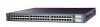
from other network devices. A feature specific to the Catalyst 3524-PWR XL switch is its ability to provide inline power to Cisco IP Phones. (Phone adapters are not required when connecting to the Catalyst 3524-PWR XL 10/100 switch ports.) Figure 1-1 shows the switch models in the series, and Table - Cisco 3550 48 | Installation Guide - Page 26
Chapter 1 Product Overview Figure 1-1 Catalyst 3500 Series XL Switches Switch Description WS-C3508G-XL 8 GBIC1-based gigabit module slots 1 SYSTEM 2 3 RPS 4 5 MODE STATUS UTIL DUPLX SPEED 6 7 8 WS-C3512-XL 12 autosensing10/100 Ethernet ports 2 GBIC-based gigabit module slots - Cisco 3550 48 | Installation Guide - Page 27
switch through a single IP address • Simple Network Management Protocol (SNMP) Power Redundancy • Connection for optional Cisco 600W Redundant Power System (RPS) that operates on AC input and supplies DC output to the switch 78-6456-04 Catalyst 3500 Series XL Hardware Installation Guide - Cisco 3550 48 | Installation Guide - Page 28
from broadcast storms • SPAN port monitoring on any port • Support for command switch redundancy • Support for Cisco GBIC modules - GigaStack GBIC - 1000BaseSX GBIC module - 1000BaseLX/LH GBIC module - 1000BaseZX GBIC module Catalyst 3500 Series XL Hardware Installation Guide 1-4 78-6456-04 - Cisco 3550 48 | Installation Guide - Page 29
and supplies DC output to the Catalyst 3524-PWR XL switch Inline Power (Catalyst 3524-PWR XL switch only) • Ability to provide inline power for Cisco IP Phones from all 24 10/100 Ethernet ports • Auto-detection and control of inline phone power on a per-port basis on all 10/100 ports • Support - Cisco 3550 48 | Installation Guide - Page 30
Figure 1-4 Catalyst 3524 XL Switch 1 2 GBIC module slots 12 1X 34 56 78 MODE SYSTEM RPS STATUS 2X UTIL DUPLX SPEED 9 10 11 12 11X 12X 13 14 13X 15 16 17 18 19 20 21 22 23 24 23X 14X 24X 10/100 ports 1 2 GBIC module slots Catalyst 3500 Series XL Hardware Installation Guide - Cisco 3550 48 | Installation Guide - Page 31
switch ports can connect, up to a distance of 100 meters, to any compatible network device: • 10BaseT-compatible devices such as workstations, Cisco IP Phones, and hubs through standard RJ-45 connectors and Category 3, 4, or 5 cabling 78-6456-04 Catalyst 3500 Series XL Hardware Installation Guide - Cisco 3550 48 | Installation Guide - Page 32
XL switches also support per-port priority override. Refer to the Cisco IOS Desktop Switching Software Configuration Guide for more information about these features. Cisco IP Phones-connected to the 10/100 ports on the Catalyst 3512, 3524, and 3548 XL switches-must be connected to an AC power source - Cisco 3550 48 | Installation Guide - Page 33
Never setting for inline power on a port, the port does not provide power even if a Cisco IP Phone is connected to it. You also can connect the Cisco IP Phone to a Catalyst 3524-PWR XL 10/100 port and to an AC power source for redundant power. The power source to which the Cisco IP Phone is first - Cisco 3550 48 | Installation Guide - Page 34
SPEED 2 3 1000BaseX GBIC module GBIC module slot Figure 1-8 Installing a GigaStack GBIC Module in the Switch Metal flap door 22081 1 SYSTEM RPS MODE STATUS UTIL DUPLX SPEED 2 3 1 2 GigaStack GBIC GBIC module slot 1-10 Catalyst 3500 Series XL Hardware Installation Guide 78-6456-04 - Cisco 3550 48 | Installation Guide - Page 35
and Cluster Manager page. The Cisco IOS Desktop Switching Software Configuration Guide describes how to use the Cluster Management Suite to monitor individual switches and how to use cluster management software to monitor all the switches in a cluster. Figure 1-9 Catalyst 3508G XL LEDs GBIC module - Cisco 3550 48 | Installation Guide - Page 36
Figure 1-10 Catalyst 3512 and 3524 XL LEDs Port LEDs Chapter 1 Product Overview SYSTEM RPS MODE STATUS UTIL DUPLX SPEED Mode button 1 1X 23 45 67 8 9 10 11 12 11X 2X 12X System LED Redundant power system LED 22028 1-12 Catalyst 3500 Series XL Hardware Installation Guide 78-6456 - Cisco 3550 48 | Installation Guide - Page 37
LEDs Port LEDs Front-Panel Description 30292 MODE SYSTEM RPS STATUS DUPLX SPEED LINE PWR Mode button 12 1X 34 56 78 9 10 11 12 11X 2X 12X System LED Redundant power system LED Status LED Duplex LED Speed LED Line power LED 78-6456-04 Catalyst 3500 Series XL Hardware Installation Guide - Cisco 3550 48 | Installation Guide - Page 38
is not powered on. System is operating normally. System is receiving power but is not functioning properly. For information on the System LED colors during POST, see the "Powering On the Switch and Running POST" section on page 2-17. 1-14 Catalyst 3500 Series XL Hardware Installation Guide 78 - Cisco 3550 48 | Installation Guide - Page 39
-AC-RPS) supports the Catalyst 3512, 3524, 3548, and 3508 XL switches. Table 1-4 RPS LED for the Catalyst 3508, 3512, 3524, and 3548 XL Switches Color Off Solid green Blinking green Amber RPS Status RPS is off or is not installed. RPS is operational. RPS and the switch AC power supply are both - Cisco 3550 48 | Installation Guide - Page 40
could have failed. Internal power supply of the switch is down, and redundancy is lost. The switch is operating on the RPS. For more information about the failure conditions on the Cisco RPS 300, refer to the Cisco Redundant Power System 300 Hardware Installation Guide. Port LEDs and Modes Each - Cisco 3550 48 | Installation Guide - Page 41
mode Port speed Port inline power Description The port duplex mode: full duplex or half duplex. The port operating speed: 10, 100, or 1000 Mbps. The inline power status: on or off. Table 1-7 Meaning of LED Colors in Different Modes on the Catalyst 3508, 3512, 3524, and 3548 XL Switches Port Mode - Cisco 3550 48 | Installation Guide - Page 42
Spanning Tree Protocol (STP). Note After a port is reconfigured, the port LED can remain amber for up to 30 seconds as STP checks the switch for possible loops. Port is operating in half duplex. Port is operating in full duplex. 1-18 Catalyst 3500 Series XL Hardware Installation Guide 78-6456-04 - Cisco 3550 48 | Installation Guide - Page 43
in Different Modes on the Catalyst 3524-PWR XL Switch Port Mode LED Color SPEED (speed) 10/100 ports Off Green 1000BaseX ports Off Green LINE PWR Off (inline power) Green Meaning Port is operating at 10 Mbps. Port is operating at 100 Mbps. Port is not operating. Port is operating at 1000 - Cisco 3550 48 | Installation Guide - Page 44
33X 35 36 37 38 39 40 41 42 43 44 45 46 Catalyst 3500 47 48 47X 2X 16X 18X 32X 34X 48X < 25% + 25% - 49% + 50% + XL 1 2 If all port LEDs on the Catalyst 3548 XL switch are green, the switch is using 50 percent or more of its total bandwidth capacity. If all - Cisco 3550 48 | Installation Guide - Page 45
Rear Panel Fans 18964 RATING 100-127/200-240V~ 1.0A/0.5A 50-60HZ AC power connector 78-6456-04 CONSOLE DC INPUTS FOR REMOTE POWER SUPPLY SPECIFIED IN MANUAL. +5V @24A, +12V @.5A RJ-45 console port Redundant power system connector Fans Catalyst 3500 Series XL Hardware Installation Guide 1-21 - Cisco 3550 48 | Installation Guide - Page 46
REMOTE POWER SUPPLY SPECIFIED IN MANUAL +3.3V @17A, +12 @1.1A CONSOLE AC power connector Fan exhaust RJ-45 console port Redundant power system connector Power Connectors You can provide power to the switch either through the internal power supply or through the Cisco RPS. 1-22 Catalyst 3500 - Cisco 3550 48 | Installation Guide - Page 47
power supply, use the supplied AC power cord to connect the AC power connector to an AC power outlet. Cisco RPS Connector Specific Cisco RPS models support specific Catalyst 3500 XL switches: • Cisco RPS 600 (model PWR600-AC-RPS)-Supports the Catalyst 3512, 3524, 3548, and 3508 XL switches • Cisco - Cisco 3550 48 | Installation Guide - Page 48
the RPS receptacle. For more information on the Cisco RPS 300, refer to the Cisco Redundant Power System 300 Hardware Installation Guide. Console Port You can connect a Catalyst 3500 XL switch to a PC by means of the console port and the supplied rollover cable and DB-9 adapter. You need to provide - Cisco 3550 48 | Installation Guide - Page 49
port, located on the rear panel of the switch, to access the CLI. If the switch is connected to your network, you can use a Telnet connection to manage the switch from a remote location. See the Cisco IOS Desktop Switching The switch supports a Catalyst 3500 Series XL Hardware Installation Guide 1-25 - Cisco 3550 48 | Installation Guide - Page 50
evolving demand for IP telephony • Use quality of service (QoS) to prioritize applications such as IP telephony during congestion and to help control both delay and jitter within the network. Use switches that support at least two queues per port to prioritize voice and data traffic as either high - Cisco 3550 48 | Installation Guide - Page 51
connect the Catalyst 3500 XL switches, again in a star configuration, to two backbone switches. If one of the backbone switches fails, the second backbone switch preserves connectivity between the switches and network resources. 78-6456-04 Catalyst 3500 Series XL Hardware Installation Guide 1-27 - Cisco 3550 48 | Installation Guide - Page 52
cluster High-Performance Workgroup Catalyst 3508 XL or 4908G-L3 switch Catalyst 3500 XL cluster Redundant Gigabit Backbone Catalyst 4908G-L3 switch Catalyst 4908G-L3 switch 1 Gbps HSRP 33090 Catalyst 3500 XL cluster 1-28 Catalyst 3500 Series XL Hardware Installation Guide 78-6456-04 - Cisco 3550 48 | Installation Guide - Page 53
performance from a server, connect the server to a Fast Ethernet or Fast EtherChannel switch port. Connecting a router to a Fast Ethernet switch port provides multiple, simultaneous access to the Internet through one line. 78-6456-04 Catalyst 3500 Series XL Hardware Installation Guide 1-29 - Cisco 3550 48 | Installation Guide - Page 54
Network Configuration Examples Chapter 1 Product Overview Figure 1-22 Small- to Medium-Sized Network Configuration Cisco 2600 router Catalyst 3500 XL GigaStack cluster 100 Mbps (200 Mbps full duplex) Gigabit server 1 Gbps (2 Gbps full duplex) Gigabit server 10/100 Mbps (20/200 Mbps full - Cisco 3550 48 | Installation Guide - Page 55
SoftPhone software integrates telephony and IP networks, where the IP network supports both voice and data. Each 10/100 inline-power port on the Catalyst 3524-PWR XL switches provides -48V DC power to the Cisco IP Phone. The IP phone can receive redundant power when it also is connected to an AC - Cisco 3550 48 | Installation Guide - Page 56
Fast EtherChannel (400 Mbps full duplex Fast EtherChannel) Catalyst 3524-PWR XL GigaStack cluster IP IP AC power source Workstations running Cisco SoftPhone software IP IP Cisco IP Phones IP IP IP Cisco IP Phones 33092 1-32 Catalyst 3500 Series XL Hardware Installation Guide 78-6456-04 - Cisco 3550 48 | Installation Guide - Page 57
. • Cisco Access gateway (such as Cisco Access Digital Trunk Gateway or Cisco Access Analog Trunk Gateway) that connects the IP network to the Public Switched Telephone Network (PSTN) or to users in an IP telephony network. 78-6456-04 Catalyst 3500 Series XL Hardware Installation Guide 1-33 - Cisco 3550 48 | Installation Guide - Page 58
network or PSTN Cisco CallManager Cisco 7200 Cisco access or 7500 router gateway Servers Catalyst 6500 switch Catalyst 3500 XL and 2900 XL GigaStack cluster 1 Gbps (2 Gbps full duplex) Catalyst 3524-PWR XL GigaStack cluster IP IP AC Workstations running power Cisco SoftPhone software source - Cisco 3550 48 | Installation Guide - Page 59
and start up your Catalyst 3500 XL switches and to interpret the power-on self-test (POST Power-on procedures • Connection procedures • Set up procedures for initial configuration • Default configuration settings • Where to go next 78-6456-04 Catalyst 3500 Series XL Hardware Installation Guide - Cisco 3550 48 | Installation Guide - Page 60
Service Personnel. Statement 88 Warning Only trained and qualified personnel should be allowed to install or replace this equipment. Statement 49 Warning Read the installation instructions before connecting the system to the power equipment damage. Statement 48 Warning The plug-socket combination - Cisco 3550 48 | Installation Guide - Page 61
39 Warning Care must be given to connecting units to the supply circuit so that wiring is not overloaded. Statement 51 Warning Unplug the power cord before you work on a system that does not have an on/off switch. Statement 20 78-6456-04 Catalyst 3500 Series XL Hardware Installation Guide 2-3 - Cisco 3550 48 | Installation Guide - Page 62
key, or other means of security. Statement 1072 The following warning applies to the Catalyst 3508, 3512, 3524, and 3548 XL switches: Warning Attach only the Cisco RPS (model PWR600-AC-RPS) to the RPS receptacle. Statement 100 Catalyst 3500 Series XL Hardware Installation Guide 2-4 78-6456-04 - Cisco 3550 48 | Installation Guide - Page 63
warning applies to the Catalyst 3524-PWR XL switch: Warning Attach only the Cisco RPS (model PWR300-AC-RPS-N1) to the RPS receptacle. Statement 100B EMC Regulatory Statements U.S.A. Taiwan U.S. regulatory information for this product is in the front matter of this manual. Warning This is - Cisco 3550 48 | Installation Guide - Page 64
and Starting Up the Switch Warning This is a Class A product based on the standard of the Voluntary Control Council for Interference by Information Technology Equipment (VCCI). If this equipment is used in a domestic environment, radio disturbance may arise. When such trouble occurs, the user may - Cisco 3550 48 | Installation Guide - Page 65
the switch to the connected devices are up to 1 meter. For specific cable lengths, refer to the document that came with the GigaStack GBIC. • Operating environment is within the ranges listed in Appendix A, "Technical Specifications." 78-6456-04 Catalyst 3500 Series XL Hardware Installation Guide - Cisco 3550 48 | Installation Guide - Page 66
3500 Series XL Hardware Installation Guide • Cisco IOS Desktop Switching Software Configuration Guide • Release Notes for the Catalyst 2900 Series XL and Catalyst 3500 Series XL Cisco IOS Release 12.0(5)XU • Cisco Documentation CD-ROM • AC power cord Catalyst 3500 Series XL Hardware Installation - Cisco 3550 48 | Installation Guide - Page 67
the cable guide to one of the mounting brackets • One RJ-45-to-RJ-45 rollover cable • One RJ-45-to-DB-9 female adapter • Cisco Information Packet, containing warranty, safety, and support information Installing the Switch in a Rack Warning To prevent bodily injury when mounting or servicing this - Cisco 3550 48 | Installation Guide - Page 68
rack, follow the instructions described in these procedures: • Removing screws from the switch • Attaching the brackets to the switch • Mounting the switch in a rack • Attaching the optional cable guide Removing Screws from the Switch If you plan to install the Catalyst 3548 XL switch in a rack - Cisco 3550 48 | Installation Guide - Page 69
Screws from the Catalyst 3548 XL Switch 46 47 48 47X 1 2 48X Catalyst 3548 XL switch 30062 Attaching the Brackets to the Switch The bracket orientation and the screws you use depend on whether you are attaching the brackets for a 19-inch or a 24-inch rack. Use two of the supplied screws to - Cisco 3550 48 | Installation Guide - Page 70
in a Rack Chapter 2 Installing and Starting Up the Switch Phillips truss-head screws 1 SYSTEM RPS MODE STATUS UTIL DUPLX SPEED 2 3 24" 24" Configuration Phillips flat-head screws Phillips truss-head screws 22440 2-12 Catalyst 3500 Series XL Hardware Installation Guide 78-6456-04 - Cisco 3550 48 | Installation Guide - Page 71
6 7 UTIL 8 DUPLX SPEED Phillips machine screws After the switch is mounted in the rack, attach the power cord to the switch. If you are using the Cisco RPS, see the Cisco RPS documentation for installation instructions. After the power is connected, the System LED turns amber for 2 seconds - Cisco 3550 48 | Installation Guide - Page 72
2 Installing and Starting Up the Switch Note The Catalyst 3548 XL switch ships with a special cable guide as shown in Figure 2-7. This cable guide secures up to 48 cables. Use the supplied black screw to mount it on the left bracket. Figure 2-6 Attaching the Cable Guide to a 3512, 3524, 3524-PWR - Cisco 3550 48 | Installation Guide - Page 73
required to attach the switch to a wall: • Attaching the brackets to the switch • Attaching the switch to a wall Attaching the Brackets to the Switch Use two of the supplied number-8 Phillips flat-head Phillips flat-head screws 78-6456-04 Catalyst 3500 Series XL Hardware Installation Guide 2-15 - Cisco 3550 48 | Installation Guide - Page 74
RPS, see the Cisco RPS documentation. After the power is connected, the system LED turns amber for 2 seconds, and then it flashes green while the switch completes a series of self-tests described in the "Powering On the Switch and Running POST" section on page 2-17. 2-16 Catalyst 3500 Series XL - Cisco 3550 48 | Installation Guide - Page 75
cord to the AC power connector on the switch. Connect the other end of the power cord to an AC power outlet. As the switch powers on, it begins POST, a series of eight tests that run automatically to ensure that the switch functions properly. When the switch begins POST, the port LEDs turn amber - Cisco 3550 48 | Installation Guide - Page 76
on both ends of the connection. You can configure the 10/100 ports on the Catalyst 3524-PWR XL switch to either automatically provide inline power when a Cisco IP Phone is connected or to never provide inline power even if a Cisco IP Phone is connected. The default setting is Auto. Caution It - Cisco 3550 48 | Installation Guide - Page 77
Pinouts" section on page B-4. Figure 2-10 Connecting to a 10/100 Switch Port MODE SYSTEM RPS STATUS UTIL DUPLX SPEED 12 1X 2X 34 56 78 9 10 11 12 11X 12X 22001 Note The Catalyst 3524-PWR XL switch can connect to a Cisco IP Phone through a straight-through, twisted-pair cable. The rear - Cisco 3550 48 | Installation Guide - Page 78
then the port LED turns green. If the port LED does not come on, the device at the other end might not be turned on, or there might be a cable problem or a problem with the adapter installed in the attached device. See Chapter 3, "Troubleshooting," for solutions to cabling problems. Reconfigure and - Cisco 3550 48 | Installation Guide - Page 79
port on the module, and store them for future use. Insert the SC connector in the fiber-optic receptacle, as shown in Figure 2-11. Figure 2-11 Connecting to a 1000BaseX Port 1 SYSTEM 2 RPS MODE STATUS UTIL DUPLX SPEED 22005 78-6456-04 Catalyst 3500 Series XL Hardware Installation Guide - Cisco 3550 48 | Installation Guide - Page 80
GBIC Module Port Connect the GigaStack cable connector to the GigaStack GBIC as shown in Figure 2-12. Figure 2-12 Connecting to a GigaStack Port 32708 MODE 1394 SYSTEM RPS STATUS UTIL DUPLX SPEED 1 1 2 1 2 2 GigaStack cable 1394 2-22 Catalyst 3500 Series XL Hardware Installation Guide 78 - Cisco 3550 48 | Installation Guide - Page 81
match these console port default characteristics: • 9600 baud • 8 data bits • 1 stop bit • No parity After you have gained access to the switch, you can change the port baud rate. See the Cisco IOS Desktop Switching Software Configuration Guide for instructions. 78-6456-04 Catalyst 3500 Series XL - Cisco 3550 48 | Installation Guide - Page 82
for a description of the pinout. Figure 2-13 Connecting to the Console Port 32709 CONSOLE DC INPUTS FOR REMOTE POWER SUPPLY SPECIFIED IN MANUAL. +5V @24A, +12V @1.0A RJ-45 Console port Step 4 Step 5 Step 6 Rollover cable Attach the supplied RJ-45-to-DB-9 female DTE adapter to a PC or attach - Cisco 3550 48 | Installation Guide - Page 83
must assign IP information. Refer to the Cisco IOS Desktop Switching Software Configuration Guide for more information. You will need the following information from your system administrator: Switch IP address Subnet mask (netmask 78-6456-04 Catalyst 3500 Series XL Hardware Installation - Cisco 3550 48 | Installation Guide - Page 84
DTE adapter if you want to connect the switch console port to a terminal. You can order a kit (part number ACS-DSBUASYN=) containing that adapter from Cisco. For console port and adapter pinout information, see the "Cable and Adapter Specifications" section on page B-4. Step 1 Step 2 Step 3 Step - Cisco 3550 48 | Installation Guide - Page 85
If you enter N to configure the switch as a member switch or as a standalone, it appears as a candidate switch in Cluster Builder and the Step 11 message is not displayed. Would you like to enable as a cluster command switch? y 78-6456-04 Catalyst 3500 Series XL Hardware Installation Guide 2-27 - Cisco 3550 48 | Installation Guide - Page 86
again at Step 1. The Cisco IOS Desktop Switching Software Configuration Guide describes how to set a password to protect the switch against unauthorized Telnet access and how to access the switch if you forget the password. 2-28 Catalyst 3500 Series XL Hardware Installation Guide 78-6456-04 - Cisco 3550 48 | Installation Guide - Page 87
preserved, and the switch does not issue BOOTP messages the next time it resets. Default Configuration Settings After you assign IP information, the switch can operate with the default configuration settings shown in Table 2-1. 78-6456-04 Catalyst 3500 Series XL Hardware Installation Guide 2-29 - Cisco 3550 48 | Installation Guide - Page 88
Starting Up the Switch Table 2-1 Default Configuration Settings Feature Default Setting Management Switch IP address, port CGMP4 Disabled. Enabled. Network Redundancy Spanning Tree Protocol Enabled. Port grouping None assigned. 2-30 Catalyst 3500 Series XL Hardware Installation Guide - Cisco 3550 48 | Installation Guide - Page 89
security Trap manager Community strings Port security Inline Power Inline power mode 1. CDP = Cisco Discovery Protocol 2. ARP = Address Resolution Protocol 3. VLAN = Virtual Local Area Network 4. CGMP = Cisco Group Management Protocol 5. SPAN = Switched Port Analyzer Default Setting Disabled - Cisco 3550 48 | Installation Guide - Page 90
Where to Go Next Chapter 2 Installing and Starting Up the Switch 2-32 Catalyst 3500 Series XL Hardware Installation Guide 78-6456-04 - Cisco 3550 48 | Installation Guide - Page 91
Guide, the Cisco IOS Desktop Switching Command Reference (online only), or the documentation that came with your SNMP application for details. This chapter describes the following topics for troubleshooting problems: • Understanding POST results • Diagnosing problems 78-6456-04 Catalyst - Cisco 3550 48 | Installation Guide - Page 92
Understanding POST Results Chapter 3 Troubleshooting Understanding POST Results Table 3-1 lists the eight POST tests and their associated LEDs. POST tests run automatically each time the switch is powered on. When the switch begins POST, the port LEDs turn amber for 2 seconds, and then they turn - Cisco 3550 48 | Installation Guide - Page 93
Chapter 3 Troubleshooting Diagnosing Problems Diagnosing Problems Common switch problems fall into the following categories: • Poor performance • No connectivity • Corrupted software Table 3-2 describes how to detect and resolve these problems. 78-6456-04 Catalyst 3500 Series XL Hardware - Cisco 3550 48 | Installation Guide - Page 94
Diagnosing Problems Chapter 3 Troubleshooting Table 3-2 Common Problems and Their Solutions Symptom Poor performance or excessive errors. Possible Cause Resolution Duplex autonegotiation mismatch. See the Cisco IOS Desktop Switching Software Configuration Guide for information on identifying - Cisco 3550 48 | Installation Guide - Page 95
Troubleshooting Diagnosing Problems Table 3-2 Common Problems and Their Solutions (continued) Symptom No connectivity. Unreadable characters on the management console. System LED is amber on the Catalyst 3508, 3512, or 3524 XL switch 6456-04 Catalyst 3500 Series XL Hardware Installation Guide 3-5 - Cisco 3550 48 | Installation Guide - Page 96
Problems Chapter 3 Troubleshooting Table 3-2 Common Problems and Their Solutions (continued) Symptom System LED is amber on the Catalyst 3524-PWR XL. Possible Cause • Internal fan fault detected. • Switch is overheating. • Nonfatal or fatal POST error detected. Cisco IP Phone fails to power - Cisco 3550 48 | Installation Guide - Page 97
. Table A-1 Technical Specifications for the Catalyst 3508G XL Switch Environmental Ranges Operating temperature Storage temperature Operating humidity Operating altitude Storage altitude Power Requirements AC input voltage DC input voltages Power consumption Physical Dimensions Weight Dimensions - Cisco 3550 48 | Installation Guide - Page 98
@8.0A, +12V @0.5A +5V @10A, +12V @0.5A +3.3V @17A +12V @1.1A Power consumption 50W 171 Btus per hour 75W 256 Btus per hour 100W 342 Btus per hour Physical Dimensions Weight 10.25 lb (4.65 kg) 8.5 lb (3.86 kg) 12 lb (5.45 kg) Dimensions (H x 1.75 x 11.82 x 17.5 in. 1.75 x 11.82 x 17.5 in - Cisco 3550 48 | Installation Guide - Page 99
Technical Specifications Table A-3 Technical Specifications for the Catalyst 3524-PWR XL Switch 48V @3A, +12V @6A 325W1 1100 Btus per hour Physical Dimensions Weight 10.25 lb (4.65 kg) Dimensions (H x W x D) 1.75 x 11.82 x 17.5 in. (4.45 x 30.02 x 44.45 cm) 1. The actual power consumption - Cisco 3550 48 | Installation Guide - Page 100
Appendix A Technical Specifications Catalyst 3500 Series XL Hardware Installation Guide A-4 78-6456-04 - Cisco 3550 48 | Installation Guide - Page 101
APPENDIX B Connector and Cable Specifications This appendix describes the Catalyst 3500 XL switch ports and the cables and adapters that you use to connect the switch to other devices. Connector Specifications 10/100 Ports The 10/100 Ethernet ports use standard RJ-45 connectors and Ethernet - Cisco 3550 48 | Installation Guide - Page 102
and Cable Specifications Figure B-1 10/100 Port Pinouts Pin Label 1 RD+ 2 RD- 3 TD+ 4 NC 5 NC 6 TD- 7 NC 8 NC 12345678 H5318 1000BaseX Ports 1000BaseX ports use duplex SC connectors, as shown in Figure B-2. Figure B-2 1000BaseX SC Connector H8707 Tx Rx Catalyst 3500 Series - Cisco 3550 48 | Installation Guide - Page 103
adapter if you want to connect the switch console port to a terminal. You can order a kit (part number ACS-DSBUASYN=) containing that adapter from Cisco. For console port and adapter pinout information, see Table B-1 and Table B-2. 78-6456-04 Catalyst 3500 Series XL Hardware Installation Guide B-3 - Cisco 3550 48 | Installation Guide - Page 104
Figure B-4 Crossover Cable Schematic Switch 3 TD+ 6 TD- Switch 3 TD+ 6 TD- 1 RD+ 2 RD- 1 RD+ 2 RD- H5579 Figure B-5 Straight-Through Cable Schematic Switch 3 TD+ 6 TD- Switch 3 RD+ 6 RD- 1 RD+ 2 RD- 1 TD+ 2 TD- H5578 Catalyst 3500 Series XL Hardware Installation Guide B-4 78-6456-04 - Cisco 3550 48 | Installation Guide - Page 105
Appendix B Connector and Cable Specifications Cable and Adapter Specifications Rollover Cable and Adapter Pinouts Identifying a Rollover Cable To identify a pin 8 on the other connector should be the same color. Pin 8 H10632 78-6456-04 Catalyst 3500 Series XL Hardware Installation Guide B-5 - Cisco 3550 48 | Installation Guide - Page 106
Cable and Adapter Specifications Appendix B Connector and Cable Specifications Connecting to a PC Use the supplied thin, flat, RJ-45-to-RJ-45 rollover cable and RJ-45-to-DB-9 female DTE adapter to connect the console port to a PC running terminal-emulation software. Figure B-7 shows how to connect - Cisco 3550 48 | Installation Guide - Page 107
not supplied with the switch. You can order a kit (part number ACS-DSBUASYN=) containing this adapter from Cisco. Table B-2 Console Port Signaling and Cabling Using a DB-25 Adapter Console Port (DTE CTS DSR RxD GND GND TxD DTR RTS 78-6456-04 Catalyst 3500 Series XL Hardware Installation Guide B-7 - Cisco 3550 48 | Installation Guide - Page 108
Cable and Adapter Specifications Appendix B Connector and Cable Specifications Catalyst 3500 Series XL Hardware Installation Guide B-8 78-6456-04 - Cisco 3550 48 | Installation Guide - Page 109
APPENDIX C Translated Safety Warnings This appendix repeats in multiple languages the warnings in this guide. These translated warnings can be used with other documents related to this guide. 78-6456-04 Catalyst 3500 Series XL Hardware Installation Guide C-1 - Cisco 3550 48 | Installation Guide - Page 110
RPS (model PWR600-AC-RPS) Appendix C Translated Safety Warnings Attaching the Cisco RPS (model PWR600-AC-RPS) This warning applies to the Catalyst 3508, 3512, 3524, and 3548 XL switches. Warning Attach only the Cisco RPS (model PWR600-AC-RPS) to the RPS receptacle. Statement 100 Waarschuwing - Cisco 3550 48 | Installation Guide - Page 111
Appendix C Translated Safety Warnings Attaching the Cisco RPS (model PWR600-AC-RPS) 78-6456-04 Catalyst 3500 Series XL Hardware Installation Guide C-3 - Cisco 3550 48 | Installation Guide - Page 112
RPS (model PWR300-AC-RPS-N1) Appendix C Translated Safety Warnings Attaching the Cisco RPS (model PWR300-AC-RPS-N1) This warning applies to the Catalyst 3524-PWR XL switch. Warning Attach only the Cisco RPS (model PWR300-AC-RPS-N1) to the RPS receptacle. Statement 100B Waarschuwing Slechts - Cisco 3550 48 | Installation Guide - Page 113
1.2.14.3 sul 'Service Personnel' contenuta nelle norme AS/NZS 3260. Advarsel Installasjon og vedlikehold av dette utstyret skal kun foretas av vedlikeholdspersonell som definert i AS/NZS 3260, klausul 1.2.14.3 Service Personnel. 78-6456-04 Catalyst 3500 Series XL Hardware Installation Guide C-5 - Cisco 3550 48 | Installation Guide - Page 114
según definido por AS/NZS 3260 Cláusula 1.2.14.3 Service Personnel. Varning! Installation och underhåll av denna utrustning får endast utföras av servicepersonal enligt definition i AS/NZS 3260 klausul 1.2.14.3 Service Personnel. Catalyst 3500 Series XL Hardware Installation Guide C-6 78-6456-04 - Cisco 3550 48 | Installation Guide - Page 115
y reemplazados exclusivamente por personal técnico adecuadamente preparado y capacitado. Varning Denna utrustning ska endast installeras och bytas ut av utbildad och kvalificerad personal. 78-6456-04 Catalyst 3500 Series XL Hardware Installation Guide C-7 - Cisco 3550 48 | Installation Guide - Page 116
Qualified Personnel Warning Appendix C Translated Safety Warnings Catalyst 3500 Series XL Hardware Installation Guide C-8 78-6456-04 - Cisco 3550 48 | Installation Guide - Page 117
Warnings Installation Instructions Warning Installation Instructions Warning Warning Read the installation instructions before connecting the system to the power source. innan du kopplar systemet till strömförsörjningsenheten. 78-6456-04 Catalyst 3500 Series XL Hardware Installation Guide C-9 - Cisco 3550 48 | Installation Guide - Page 118
that is connected to power lines, remove jewelry (including rings, necklaces, and watches). Metal objects will heat up when connected to power and ground and can des blessures graves ou souder l'objet métallique aux bornes. C-10 Catalyst 3500 Series XL Hardware Installation Guide 78-6456-04 - Cisco 3550 48 | Installation Guide - Page 119
. Metallobjekt hettas upp när de kopplas ihop med ström och jord och kan förorsaka allvarliga brännskador; metallobjekt kan också sammansvetsas med kontakterna. 78-6456-04 Catalyst 3500 Series XL Hardware Installation Guide C-11 - Cisco 3550 48 | Installation Guide - Page 120
Jewelry Removal Warning Appendix C Translated Safety Warnings C-12 Catalyst 3500 Series XL Hardware Installation Guide 78-6456-04 - Cisco 3550 48 | Installation Guide - Page 121
the chassis falls, it can cause severe bodily injury and equipment damage. Statement 48 Waarschuwing Het chassis mag niet op andere apparatuur gestapeld te worden. Als het kroppsskada såväl som skada på utrustningen uppstå. 78-6456-04 Catalyst 3500 Series XL Hardware Installation Guide C-13 - Cisco 3550 48 | Installation Guide - Page 122
Stacking the Chassis Warning Appendix C Translated Safety Warnings C-14 Catalyst 3500 Series XL Hardware Installation Guide 78-6456-04 - Cisco 3550 48 | Installation Guide - Page 123
veces de dispositivo de desconexión principal. Varning! Man måste alltid kunna komma åt stickproppen i uttaget, eftersom denna koppling utgör den huvudsakliga frånkopplingsanordningen. 78-6456-04 Catalyst 3500 Series XL Hardware Installation Guide C-15 - Cisco 3550 48 | Installation Guide - Page 124
Warning Overtemperature Warning Appendix C Translated Safety Warnings Warning To prevent the switch from overheating, do not operate it in an area that exceeds the spazio libero di 7,6 cm intorno alle aperture di ventilazione. C-16 Catalyst 3500 Series XL Hardware Installation Guide 78-6456-04 - Cisco 3550 48 | Installation Guide - Page 125
maximalt rekommenderade omgivningstemperaturen som är 45°C. Kontrollera att det finns minst 7,6 cm fritt utrymme runt ventilationsöppningarna så att luftflödet inte begränsas. 78-6456-04 Catalyst 3500 Series XL Hardware Installation Guide C-17 - Cisco 3550 48 | Installation Guide - Page 126
Overtemperature Warning Appendix C Translated Safety Warnings C-18 Catalyst 3500 Series XL Hardware Installation Guide 78-6456-04 - Cisco 3550 48 | Installation Guide - Page 127
Warning Warning The device is designed to work with TN power systems. Statement 19 Waarschuwing Het apparaat is ontworpen om te functioneren met ! Enheten är konstruerad för användning tillsammans med elkraftssystem av TN-typ. 78-6456-04 Catalyst 3500 Series XL Hardware Installation Guide C-19 - Cisco 3550 48 | Installation Guide - Page 128
el equipo, conectar la tierra la primera y desconectarla la última. Varning! Vid installation av enheten måste jordledningen alltid anslutas först och kopplas bort sist. C-20 Catalyst 3500 Series XL Hardware Installation Guide 78-6456-04 - Cisco 3550 48 | Installation Guide - Page 129
qu'un disjoncteur de 120 V alt., 15 A U.S. maximum (240 V alt., 10 A international) est utilisé sur les conducteurs de phase (conducteurs de charge). 78-6456-04 Catalyst 3500 Series XL Hardware Installation Guide C-21 - Cisco 3550 48 | Installation Guide - Page 130
att säkring eller överspänningsskydd används på fasledarna (samtliga strömförande ledare) för internationellt bruk max. 240 V växelström, 10 A (i USA max. 120 V växelström, 15 A). C-22 Catalyst 3500 Series XL Hardware Installation Guide 78-6456-04 - Cisco 3550 48 | Installation Guide - Page 131
esté conectado a tierra durante el uso normal. Varning! Denna utrustning är avsedd att jordas. Se till att värdenheten är jordad vid normal användning. 78-6456-04 Catalyst 3500 Series XL Hardware Installation Guide C-23 - Cisco 3550 48 | Installation Guide - Page 132
Warning Warning Care must be given to connecting units to the supply circuit so that wiring is not overloaded. Statement 51 Waarschuwing nøye med å koble enheter til strømforsyningskretsen slik at ledningene ikke overbelastes. C-24 Catalyst 3500 Series XL Hardware Installation Guide 78-6456-04 - Cisco 3550 48 | Installation Guide - Page 133
inte överbelastas. No On/Off Switch Warning Warning Unplug the power cord before you work on a system that does not have an on/off switch. Statement 20 Waarschuwing Voordat u aan av/på-bryter, skal strømledningen trekkes ut. 78-6456-04 Catalyst 3500 Series XL Hardware Installation Guide C-25 - Cisco 3550 48 | Installation Guide - Page 134
No On/Off Switch Warning Appendix C Translated Safety Warnings Aviso Antes de começar a trabalhar num sistema que não possua um alimentación. Varning! Dra ur nätsladden innan du utför arbete på ett system utan strömbrytare. C-26 Catalyst 3500 Series XL Hardware Installation Guide 78-6456-04 - Cisco 3550 48 | Installation Guide - Page 135
C Translated Safety Warnings Power Supply Warning Power Supply Warning Warning Do not touch the power supply when the power cord is connected. For systems with a power switch, line voltages are present within the power supply even when the power switch is off and the power cord is connected. For - Cisco 3550 48 | Installation Guide - Page 136
Power Supply Warning Appendix C Translated Safety Warnings Avvertenza Non toccare l'alimentatore se il cavo dell' system utan strömbrytare finns det nätspänning i strömförsörjningsenheten när nätsladden är ansluten. C-28 Catalyst 3500 Series XL Hardware Installation Guide 78-6456-04 - Cisco 3550 48 | Installation Guide - Page 137
Appendix C Translated Safety Warnings Power Supply Warning 78-6456-04 Catalyst 3500 Series XL Hardware Installation Guide C-29 - Cisco 3550 48 | Installation Guide - Page 138
de descargas eléctricas en la atmósfera. Varning! Vid åska skall du aldrig utföra arbete på systemet eller ansluta eller koppla loss kablar. C-30 Catalyst 3500 Series XL Hardware Installation Guide 78-6456-04 - Cisco 3550 48 | Installation Guide - Page 139
eseguito secondo le leggi e regolazioni locali. Advarsel Endelig kassering av dette produktet skal være i henhold til alle relevante nasjonale lover og bestemmelser. 78-6456-04 Catalyst 3500 Series XL Hardware Installation Guide C-31 - Cisco 3550 48 | Installation Guide - Page 140
deshacerse por completo de este producto debe seguir todas las leyes y reglamentos nacionales. Varning! Vid deponering hanteras produkten enligt gällande lagar och bestämmelser. C-32 Catalyst 3500 Series XL Hardware Installation Guide 78-6456-04 - Cisco 3550 48 | Installation Guide - Page 141
If the rack is provided with stabilizing devices, install the stabilizers before mounting or servicing the unit in the rack. Statement 1006 Waarschuwing Om lichamelijk letsel te voorkomen wanneer tai sen huoltamista siinä. 78-6456-04 Catalyst 3500 Series XL Hardware Installation Guide C-33 - Cisco 3550 48 | Installation Guide - Page 142
Chassis Warning-Rack-Mounting and Servicing Appendix C Translated Safety Warnings Attention Pour éviter toute blessure corporelle pendant dispositivi prima di montare o di procedere alla manutenzione dell'unità nel supporto. C-34 Catalyst 3500 Series XL Hardware Installation Guide 78-6456-04 - Cisco 3550 48 | Installation Guide - Page 143
Appendix C Translated Safety Warnings Chassis Warning-Rack-Mounting and Servicing Advarsel Unngå fysiske skader under montering eller reparasjonsarbeid på denne enheten når mantenimiento del equipo instalado en el bastidor. 78-6456-04 Catalyst 3500 Series XL Hardware Installation Guide C-35 - Cisco 3550 48 | Installation Guide - Page 144
Chassis Warning-Rack-Mounting and Servicing Appendix C Translated Safety Warnings Varning! För att undvika kroppsskada när du installerar eller monteras fast innan enheten installeras eller underhålls på ställningen. • • • C-36 Catalyst 3500 Series XL Hardware Installation Guide 78-6456-04 - Cisco 3550 48 | Installation Guide - Page 145
Appendix C Translated Safety Warnings • • • • • • Chassis Warning-Rack-Mounting and Servicing 78-6456-04 Catalyst 3500 Series XL Hardware Installation Guide C-37 - Cisco 3550 48 | Installation Guide - Page 146
ensure that all power is OFF, locate the circuit breaker on the panel board that services the DC circuit, switch the circuit breaker to the OFF position, and tape the switch handle of the mit Klebeband in der AUS-Stellung fest. C-38 Catalyst 3500 Series XL Hardware Installation Guide 78-6456-04 - Cisco 3550 48 | Installation Guide - Page 147
Appendix C Translated Safety Warnings Chassis Power Connection Warning Avvertenza Prima di collegare o distaccare i cavi elettrici o di messa a likströmskretsen och tejpa fast överspänningsskyddets omkopplare i FRÅN-läget. 78-6456-04 Catalyst 3500 Series XL Hardware Installation Guide C-39 - Cisco 3550 48 | Installation Guide - Page 148
Chassis Power Connection Warning Appendix C Translated Safety Warnings C-40 Catalyst 3500 Series XL Hardware Installation Guide 78-6456-04 - Cisco 3550 48 | Installation Guide - Page 149
exist on inline power circuits if interconnections are in a restricted access location and users and service people who are authorized to access the location d'accès restreint et que les utilisateurs et les responsables du service autorisés à accéder à cet emplacement ne soient conscients du - Cisco 3550 48 | Installation Guide - Page 150
do perigo. Uma área de acesso restrito só pode ser acessada com o uso de uma ferramenta, fechadura e chave especial ou de outros meios de segurança. C-42 Catalyst 3500 Series XL Hardware Installation Guide 78-6456-04 - Cisco 3550 48 | Installation Guide - Page 151
medvetna om risken. Ett begränsat område kan bara nås med ett speciellt verktyg eller lås, en speciell nyckel eller någon annan säkerhetsmetod. 78-6456-04 Catalyst 3500 Series XL Hardware Installation Guide C-43 - Cisco 3550 48 | Installation Guide - Page 152
Shock Hazard from Interconnections Warning Appendix C Translated Safety Warnings C-44 Catalyst 3500 Series XL Hardware Installation Guide 78-6456-04 - Cisco 3550 48 | Installation Guide - Page 153
to 2-18 described 1-7 groupings 1-7 illustrated 1-5 1000BaseX ports 1-9 cable lengths 2-7 connecting to 2-20 to 2-23 connectors and cables B-2 to B-3 illustrated 1-9 19- and 24-inch racks 2-9 A AC power connecting to 2-17 connector 1-22 specifications A-1, A-2, A-3 adapter pinouts, terminal RJ-45-to - Cisco 3550 48 | Installation Guide - Page 154
xii crossover cable connectivity problems 3-5 pinout B-4 D default characteristics of the console port 2-23 default configuration 2-30 to 2-31 designing your network, examples 1-25 desk mounting 2-17 diagnosing problems 3-3 IN-2 Catalyst 3500 Series XL Hardware Installation Guide 78-6456-04 - Cisco 3550 48 | Installation Guide - Page 155
1-17, 1-18 HP OpenView 1-25 humidity A-1, A-2, A-3 I IEEE 802.1p 1-3 inline power 1-8, 2-18 to 2-19 LED 1-17, 1-19 troubleshooting 3-6 installation guidelines 2-7 rack-mount 2-9 See also procedures warning C-9 Inter-Switch Link (ISL) 1-3 Catalyst 3500 Series XL Hardware Installation Guide IN-3 - Cisco 3550 48 | Installation Guide - Page 156
PWR 1-17 port 1-16 to 1-20 POST results 2-17, 3-2 RPS 1-15 speed 1-17 STAT 1-16 status 1-18 system 1-14 UTL 1-16, 1-18 lightning activity warning C-30 line power See inline power M management features and defaults 2-30 Mode button 1-11, 1-16 Mode label (on Catalyst 3548 XL only) 1-16 models, switch - Cisco 3550 48 | Installation Guide - Page 157
, related xviii Public Switched Telephone Network See PSTN Q qualified personnel warning C-7 R rack installation 2-9 bracket mounting points 2-10 rack-mounting 2-13 rear panel 1-21 to 1-22 clearance 2-8 Redundant Power Supply 78-6456-04 Catalyst 3500 Series XL Hardware Installation Guide IN-5 - Cisco 3550 48 | Installation Guide - Page 158
2-17 technical specifications A-1 Telnet, and accessing the CLI 1-25 temperature operating A-1 warning C-16 terminal, connecting to switch 2-23 terminal emulation software 2-23 TN power warning C-19 translated warnings C-1 troubleshooting 3-1 to 3-5 U UTL LED 1-16, 1-17 IN-6 Catalyst 3500 Series - Cisco 3550 48 | Installation Guide - Page 159
Index V Visual Switch Manager (VSM) 1-24 VSM 1-24 W wall-mounting 2-15 to 2-16 warnings defined xiii installation 2-2 translated C-1 78-6456-04 Catalyst 3500 Series XL Hardware Installation Guide IN-7 - Cisco 3550 48 | Installation Guide - Page 160
Index IN-8 Catalyst 3500 Series XL Hardware Installation Guide 78-6456-04
-
 1
1 -
 2
2 -
 3
3 -
 4
4 -
 5
5 -
 6
6 -
 7
7 -
8
-
9
-
10
-
11
-
12
-
13
-
14
-
15
-
16
-
17
-
18
-
19
-
20
-
21
-
22
-
23
-
24
-
25
-
26
-
27
-
28
-
29
-
30
-
31
-
32
-
33
-
34
-
35
-
36
-
37
-
38
-
39
-
40
-
41
-
42
-
43
-
44
-
45
-
46
-
47
-
48
-
49
-
50
-
51
-
52
-
53
-
54
-
55
-
56
-
57
-
58
-
59
-
60
-
61
-
62
-
63
-
64
-
65
-
66
-
67
-
68
-
69
-
70
-
71
-
72
-
73
-
74
-
75
-
76
-
77
-
78
-
79
-
80
-
81
-
82
-
83
-
84
-
85
-
86
-
87
-
88
-
89
-
90
-
91
-
92
-
93
-
94
-
95
-
96
-
97
-
98
-
99
-
100
-
101
-
102
-
103
-
104
-
105
-
106
-
107
-
108
-
109
-
110
-
111
-
112
-
113
-
114
-
115
-
116
-
117
-
118
-
119
-
120
-
121
-
122
-
123
-
124
-
125
-
126
-
127
-
128
-
129
-
130
-
131
-
132
-
133
-
134
-
135
-
136
-
137
-
138
-
139
-
140
-
141
-
142
-
143
-
144
-
145
-
146
-
147
-
148
-
149
-
150
-
151
-
152
-
153
-
154
-
155
-
156
-
157
-
158
-
159
-
160
 |
 |

Corporate Headquarters
Cisco Systems, Inc.
170 West Tasman Drive
San Jose, CA 95134-1706
USA
Tel:
408 526-4000
800 553-NETS (6387)
Fax:
408 526-4100
Catalyst 3500 Series XL Hardware
Installation Guide
August 2003
Customer Order Number: DOC-786456=
Text Part Number: 78-6456-04