Cisco 4404 Quick Start Guide
Cisco 4404 - Wireless LAN Controller Manual
 |
View all Cisco 4404 manuals
Add to My Manuals
Save this manual to your list of manuals |
Cisco 4404 manual content summary:
- Cisco 4404 | Quick Start Guide - Page 1
a Service Request 6 Cisco 90-Day Limited Hardware Warranty Terms 1 About this Guide This guide is designed to help you install and minimally configure your Cisco 4400 Series Wireless LAN Controller. This guide covers the following controller models: 4402-25, 4402-50, 4404-25, 4404-50, and 4404-100. - Cisco 4404 | Quick Start Guide - Page 2
below are general warnings that are applicable to the entire guide. Translated versions of the safety warnings in this guide are provided in the Safety Warnings for Cisco 4400 Wireless LAN Controllers document that accompanies this guide. Warning This warning symbol means danger. You are in - Cisco 4404 | Quick Start Guide - Page 3
by Information Technology Equipment (VCCI). If this equipment is used in a domestic environment, radio disturbance may arise. When such trouble occurs, the user may be required to take corrective actions. 2 Introduction to the Controller Cisco 4400 series wireless LAN controllers offer the - Cisco 4404 | Quick Start Guide - Page 4
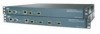
access points per port due to bandwidth constraints. The 4404-25, 4404-50, and 4404-100 models allow a total of 25, 50, or 100 access points to join the controller. Figure 1 shows the front panel layout of the 4400 series controller. Figure 1 Front Panel Layout 155837 LINK ACT SERVICE CONSOLE - Cisco 4404 | Quick Start Guide - Page 5
data transmission over the service port. Solid green indicates power supply # is operational. Solid red indicates an undervoltage condition detected on one of the DC/DC converters. Off indicates normal operation. This LED behavior may also be defined by the controller software. Solid green followed - Cisco 4404 | Quick Start Guide - Page 6
Contents Each access point package contains the following items: • Cisco 4400 series wireless LAN controller and power cord • Mounting hardware kit • Translated Safety Warnings for Cisco 4400 Series Wireless LAN Controllers • This guide • Cisco product registration and Cisco documentation feedback - Cisco 4404 | Quick Start Guide - Page 7
before you can install the controller: • Wireless LAN controller hardware - Controller with factory-supplied power cord and mounting hardware - Network, operating system service network, and access point cables as required • Command-line interface (CLI) console - VT-100 terminal emulator on CLI - Cisco 4404 | Quick Start Guide - Page 8
IP address, such as 1.1.1.1, used by all Cisco wireless LAN controller Layer 3 security and mobility managers). • A Cisco wireless LAN controller mobility group name, if required. • An 802.11 network name (SSID) for WLAN 1. This is the default SSID that the access points use when they join with the - Cisco 4404 | Quick Start Guide - Page 9
controller weighs 15.2 lbs (6.95 kg). For safety, two or more people must work together to perform the rack mount installation. • Install the SFP modules as described in the 1000BASE-SX, 1000BASE-LX, and 1000BASE-T SFP Module Quick Start Guide. • If you have purchased an extra power supply module - Cisco 4404 | Quick Start Guide - Page 10
have more than one power supply connection. All connections must be removed to de-energize the unit. Statement 1028 Connecting the Controller's Console Port Before you can configure the controller for basic operations, you need to connect it to a PC that uses a VT-100 terminal emulator (such as - Cisco 4404 | Quick Start Guide - Page 11
operating system software initialization (code download and POST verification) and basic configuration as shown in the following sample bootup display: Bootloader 3.4.0.0. (Feb 2 2006 - 19:14:47) Motorola PowerPC ProcessorID=00000000 Rev. PVR=80200020 Cisco Systems INC., 4400 Wireless LAN Switch - Cisco 4404 | Quick Start Guide - Page 12
image 3. Manually update images 4. Change active boot image 5. Clear Configuration Please enter your choice: Note Enter 1 to run the current software, enter 2 to run the previous software, or enter 5 to run the current software and set the controller configuration to factory defaults. Do not - Cisco 4404 | Quick Start Guide - Page 13
RFID Tag Tracking: ok Starting Power Supply and Fan Status Monitoring Service: ok Starting WLAN Control Protocol (WCP): wcpSysInit: Out of factory boot: Initialize ports and IP address for interfaces wcpSysInit: Setting IP address for MGMT interface OK wcpSysInit: Setting LAG for MGMT interface OK - Cisco 4404 | Quick Start Guide - Page 14
24 ASCII characters for each. The default administrative username and password are admin and admin, respectively. If you want the controller's service-port interface to obtain an IP address from a DHCP server, enter DHCP. If you do not want to use the service port or if you want to assign a static - Cisco 4404 | Quick Start Guide - Page 15
address, such as 1.1.1.1. Note The virtual interface is used to support mobility management, DHCP relay, and embedded Layer 3 security such as guest web authentication and VPN termination. All controllers within a mobility group must be configured with the same virtual interface IP address. Step - Cisco 4404 | Quick Start Guide - Page 16
basic functionality of the controller and allows access points that have joined the controller to enable their radios. Step 11 Enter yes to allow clients to assign their own IP address or no to make clients request an IP address from a DHCP server. Step 12 To configure a RADIUS server now, enter - Cisco 4404 | Quick Start Guide - Page 17
current date and time on the controller before allowing the access points to connect to it. Verifying Interface Settings and Port Operation Follow these steps to verify that your interface configurations have been set properly and the controller's ports are operational. Step 1 Enter show interface - Cisco 4404 | Quick Start Guide - Page 18
the Cisco Wireless LAN Controller Configuration Guide for more information. Step 2 Enter show port summary. The following information appears, showing the status of the controller's distribution system ports, which serve as the data path between the controller and Cisco lightweight access points - Cisco 4404 | Quick Start Guide - Page 19
to the switch's service port and the appropriate cable to connect the PC to the management network. Connecting Access Points After you have configured the controller, use Category-5, Category-5e, Category-6, or Category-7 Ethernet cables to connect Cisco lightweight access points to the network - Cisco 4404 | Quick Start Guide - Page 20
these steps to install a power supply unit. Step 1 Locate the empty power supply slot on the controller's back panel. See Figure 3. Figure 3 Controller Power Supply Slots 142297 Slot 1 Slot 2 Note The power supply units are hot swappable. Step 2 Step 3 Step 4 Use a Phillips screwdriver to - Cisco 4404 | Quick Start Guide - Page 21
Hz electrical outlet. Make sure that both power supply units are turned on. Installing a VPN Termination Module VPN termination modules provide extra processing power needed to support the termination of client VPN sessions on the controller. You can order these modules and install them in all 4400 - Cisco 4404 | Quick Start Guide - Page 22
two power supply units, remove both power cords. Step 2 Locate the VPN termination module slot on the rear panel of the controller. See Figure 5. Figure 5 VPN Termination Module Slots 146191 1 2 1 VPN termination module slot 1 2 VPN termination module slot 0 Step 3 Step 4 Step 5 Use a standard - Cisco 4404 | Quick Start Guide - Page 23
hardware warranty and various services that you can use during the warranty period. Your formal Warranty Statement, including the warranties and license agreements applicable to Cisco software, is available on Cisco.com. Follow these steps to access and download the Cisco Information Packet and your - Cisco 4404 | Quick Start Guide - Page 24
document. c. Click Go. The Cisco warranty page appears. d. Review the document online, or click the PDF icon to download and print the document in Adobe Portable Document Format (PDF). You can also contact the Cisco service and support website for assistance: http://www.cisco.com/cisco/web/support - Cisco 4404 | Quick Start Guide - Page 25
Product serial number Maintenance contract number 25 - Cisco 4404 | Quick Start Guide - Page 26
26 - Cisco 4404 | Quick Start Guide - Page 27
27 - Cisco 4404 | Quick Start Guide - Page 28
28 - Cisco 4404 | Quick Start Guide - Page 29
29 - Cisco 4404 | Quick Start Guide - Page 30
30 - Cisco 4404 | Quick Start Guide - Page 31
31 - Cisco 4404 | Quick Start Guide - Page 32
trademarks. Third party trademarks mentioned are the property of their respective owners. The use of the word partner does not imply a partnership relationship between Cisco and any other company. (1005R) © 2008 Cisco Systems, Inc. All rights reserved. Printed in the USA on recycled paper containing
-
 1
1 -
 2
2 -
 3
3 -
 4
4 -
 5
5 -
 6
6 -
 7
7 -
8
-
9
-
10
-
11
-
12
-
13
-
14
-
15
-
16
-
17
-
18
-
19
-
20
-
21
-
22
-
23
-
24
-
25
-
26
-
27
-
28
-
29
-
30
-
31
-
32
 |
 |

Q
UICK
S
TART
G
UIDE
Cisco 4400 Series Wireless LAN Controllers
INCLUDING LICENSE AND WARRANTY
1
About this Guide
2
Introduction to the Controller
3
Unpacking and Preparing the Controller for Operation
4
Using the Startup Wizard
5
Obtaining Documentation and Submitting a Service Request
6
Cisco 90-Day Limited Hardware Warranty Terms
1
About this Guide
This guide is designed to help you install and minimally configure your Cisco 4400 Series
Wireless LAN Controller. This guide covers the following controller models: 4402-25,
4402-50, 4404-25, 4404-50, and 4404-100.