Cisco AIR-ANT5145V-R User Guide
Cisco AIR-ANT5145V-R Manual
 |
View all Cisco AIR-ANT5145V-R manuals
Add to My Manuals
Save this manual to your list of manuals |
Cisco AIR-ANT5145V-R manual content summary:
- Cisco AIR-ANT5145V-R | User Guide - Page 1
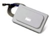
Aironet 4.5-dBi Low Profile Omnidirectional Antenna (AIR-ANT5145V-R) This document describes the Cisco Aironet 4.5-dBi Diversity Omnidirectional Antenna (AIR-ANT5145V-R), and provides instructions for mounting it. The antenna operates in the 5-GHz frequency range and is designed for use indoors - Cisco AIR-ANT5145V-R | User Guide - Page 2
36 in. (91.4 cm) Plenum rated UV stable LMR-185 2 RP-TNC Male 5 in. (12.7 cm) 3 in. (7.6 cm) 0.75 oz (21.2 g) -22°F - 158°F (-30°C - 70°C) -40°F - 185°F (-40°C - 85°C) Yes Indoor, office E-Plane Pattern Cisco Aironet 4.5-dBi Low Profile Omnidirectional Antenna (AIR-ANT5145V-R) 2 78-16467-03 - Cisco AIR-ANT5145V-R | User Guide - Page 3
5-GHz Cisco Aironet radio device that utilizes reverse polarity Neil Councilman (RP-TNC) connectors. Installation Guidelines Because the antenna transmits and receives radio signals, they are susceptible to RF obstructions and common sources of interference that can reduce throughput and range of - Cisco AIR-ANT5145V-R | User Guide - Page 4
3 Mounting bracket Figure 2 shows how the antenna mounting bracket is attached to a suspend ceiling T-rail using the attached clips. Figure 2 Antenna Mounting Bracket Attached Mounting Clip Location 146340 Cisco Aironet 4.5-dBi Low Profile Omnidirectional Antenna (AIR-ANT5145V-R) 4 78-16467-03 - Cisco AIR-ANT5145V-R | User Guide - Page 5
cable through its respective access hole. Grasp the ceiling T-rail as closely as possible to the mounting bracket while aligning the antenna with the retaining tabs. Snap the antenna over the retaining tabs. 78-16467-03 Cisco Aironet 4.5-dBi Low Profile Omnidirectional Antenna (AIR-ANT5145V-R) 5 - Cisco AIR-ANT5145V-R | User Guide - Page 6
fastened to the antenna mounting bracket, remove them. Choose a location in which to install the antenna. Remove the adjacent ceiling panels on each side of the T-rail on which the antenna is to be installed. Cisco Aironet 4.5-dBi Low Profile Omnidirectional Antenna (AIR-ANT5145V-R) 6 78-16467-03 - Cisco AIR-ANT5145V-R | User Guide - Page 7
. Connect the antenna cables. Replace the ceiling panels. Figure 4 Attached Clip Mounting Details 5 146342 4 12 3 1 Antenna 2 Mounting bracket 3 Antenna connectors 3 4 4 Mounting clips 5 Ceiling T-rail 78-16467-03 Cisco Aironet 4.5-dBi Low Profile Omnidirectional Antenna (AIR-ANT5145V-R) 7 - Cisco AIR-ANT5145V-R | User Guide - Page 8
cable. The mating connector to the antenna is an appropriate RP-TNC jack. Obtaining Documentation and Submitting a Service Request For information on obtaining documentation, submitting a service request, and gathering additional information, see the monthly What's New in Cisco Product Documentation
-
 1
1 -
 2
2 -
 3
3 -
 4
4 -
 5
5 -
 6
6 -
 7
7 -
8
 |
 |

Corporate Headquarters:
© 2006 Cisco Systems, Inc. All rights reserved.
Cisco Systems, Inc., 170 West Tasman Drive, San Jose, CA 95134-1706
USA
Cisco Aironet 4.5-dBi Low Profile
Omnidirectional Antenna (AIR-ANT5145V-R)
This document describes the Cisco Aironet 4.5-dBi Diversity Omnidirectional Antenna
(AIR-ANT5145V-R), and provides instructions for mounting it. The antenna operates in the 5-GHz
frequency range and is designed for use indoors.
The following information is provided in this document.
•
Technical Specifications, page 2
•
System Requirements, page 3
•
Installation Guidelines, page 3
•
Safety Instructions, page 3
•
Installing the Antenna, page 4
•
Obtaining Documentation and Submitting a Service Request, page 8