Cisco IPS-4240-K9 User Guide
Cisco IPS-4240-K9 - Intrusion Protection Sys 4240 Manual
 |
UPC - 746320950679
View all Cisco IPS-4240-K9 manuals
Add to My Manuals
Save this manual to your list of manuals |
Cisco IPS-4240-K9 manual content summary:
- Cisco IPS-4240-K9 | User Guide - Page 1
Installing Cisco Intrusion Prevention System Appliances and Modules 5.0 Americas Headquarters Cisco Systems, Inc. 170 West Tasman Drive San Jose, CA 95134-1706 USA http://www.cisco.com Tel: 408 526-4000 800 553-NETS (6387) Fax: 408 527-0883 Customer Order Number: DOC=7816124 Text Part Number: 78- - Cisco IPS-4240-K9 | User Guide - Page 2
, and figures included in the document are shown for illustrative purposes only. Any use of actual IP addresses in illustrative content is unintentional and coincidental. Installing Cisco Intrusion Prevention System Appliances and Modules 5.0 © 2005-2008 Cisco Systems, Inc. All rights reserved. - Cisco IPS-4240-K9 | User Guide - Page 3
1-14 Correcting the Time on the Sensor 1-16 Installation Preparation 1-16 Site and Safety Guidelines 1-17 Site Guidelines 1-17 Rack Configuration Guidelines 1-18 Electrical Safety Guidelines 1-18 Power Supply Guidelines 1-19 Installing Cisco Intrusion Prevention System Appliances and Modules 5.0 iii - Cisco IPS-4240-K9 | User Guide - Page 4
the Compact Flash Device 3-17 Removing the Compact Flash Device 3-17 Replacing the Compact Flash Device 3-18 Removing and Installing the 4FE Card 3-19 Removing the 4FE Card 3-20 Installing the 4FE Card 3-22 Installing Cisco Intrusion Prevention System Appliances and Modules 5.0 iv 78-16124-01 - Cisco IPS-4240-K9 | User Guide - Page 5
Assemblies in the Rack 4-28 Installing IPS-4240 and IPS-4255 5-1 Introducing IPS-4240 and IPS-4255 5-1 Front and Back Panel Features 5-2 Specifications 5-4 Accessories 5-5 Rack Mounting 5-6 Installing IPS-4240 and IPS-4255 5-7 Installing Cisco Intrusion Prevention System Appliances and Modules 5.0 v - Cisco IPS-4240-K9 | User Guide - Page 6
13 Cisco IOS Software 7-14 Powering IDSM-2 Up and Down 7-15 Catalyst Software 7-15 Cisco IOS Software 7-15 Installing NM-CIDS 8-1 Specifications 8-1 Software and Hardware Requirements 8-2 Hardware Architecture 8-3 Front Panel Features 8-4 Installing Cisco Intrusion Prevention System Appliances and - Cisco IPS-4240-K9 | User Guide - Page 7
Service Programs for IPS Products 10-7 Obtaining and Installing the License Key 10-8 Using IDM 10-8 Using the CLI 10-9 Cisco IPS Active Update Bulletins 10-11 Accessing IPS Documentation 10-12 Cisco Security Center 10-13 Contents 78-16124-01 Installing Cisco Intrusion Prevention System Appliances - Cisco IPS-4240-K9 | User Guide - Page 8
Contents Installing Cisco Intrusion Prevention System Appliances and Modules 5.0 viii 78-16124-01 - Cisco IPS-4240-K9 | User Guide - Page 9
Preface This guide describes how to install appliances and modules that support Cisco IPS 5.0. It includes a glossary that contains expanded acronyms and pertinent IPS terms. It is part of the documentation set for Cisco Intrusion Prevention System 5.0. Use this guide in conjunction with the - Cisco IPS-4240-K9 | User Guide - Page 10
Series Appliance Sensor • Installing and Using Cisco Intrusion Prevention System Device Manager 5.0 • Configuring the Cisco Intrusion Prevention System Sensor Using the Command Line Interface 5.0 • Cisco Intrusion Prevention System Command Reference 5.0 Installing Cisco Intrusion Prevention System - Cisco IPS-4240-K9 | User Guide - Page 11
as a Really Simple Syndication (RSS) feed and set content to be delivered directly to your desktop using a reader application. The RSS feeds are a free service and Cisco currently supports RSS Version 2.0. 78-16124-01 Installing Cisco Intrusion Prevention System Appliances and Modules 5.0 xi - Cisco IPS-4240-K9 | User Guide - Page 12
Obtaining Documentation and Submitting a Service Request Preface Installing Cisco Intrusion Prevention System Appliances and Modules 5.0 xii 78-16124-01 - Cisco IPS-4240-K9 | User Guide - Page 13
Traffic The sensor can operate in either promiscuous or inline mode. Figure 1-1 on page 1-2 shows how you can deploy a combination of sensors operating in both inline (IPS) and promiscuous (IDS) modes to protect your network. 78-16124-01 Installing Cisco Intrusion Prevention System Appliances and - Cisco IPS-4240-K9 | User Guide - Page 14
-TCP-based services, no action is taken. Additionally, TCP resets are not guaranteed to tear down an offending session because of limitations in the TCP protocol. On IDS-4250-XL, TCP resets are sent through the TCP reset interface. Installing Cisco Intrusion Prevention System Appliances and Modules - Cisco IPS-4240-K9 | User Guide - Page 15
traffic rather than the actual forwarded packet. The advantage of operating in promiscuous mode is that the IPS does not affect the packet flow with the forwarded traffic. The disadvantage of operating in 78-16124-01 Installing Cisco Intrusion Prevention System Appliances and Modules 5.0 1-3 - Cisco IPS-4240-K9 | User Guide - Page 16
.1q headers. Note The TCP resets need 802.1q headers to tell which VLAN the resets should be sent on. • When a network tap is used for monitoring a connection. Note Taps do not allow incoming traffic from the sensor. Installing Cisco Intrusion Prevention System Appliances and Modules 5.0 1-4 78 - Cisco IPS-4240-K9 | User Guide - Page 17
GigabitEthernet0/0 GigabitEthernet0/1 N/A All 2/02/1 GigabitEthernet0/0 GigabitEthernet0/1 0/70/8 GigabitEthernet0/2 0/00/1 0/00/2 0/00/3 0/10/2 0/10/3 0/20/3 Management0/0 78-16124-01 Installing Cisco Intrusion Prevention System Appliances and Modules 5.0 1-5 - Cisco IPS-4240-K9 | User Guide - Page 18
Cisco IPS software, see Obtaining Cisco IPS Software, page 10-1. Caution Installing the most recent software (version 5.0) on unsupported sensors may yield unpredictable results. We do not support software installed on unsupported platforms. Installing Cisco Intrusion Prevention System Appliances - Cisco IPS-4240-K9 | User Guide - Page 19
IDS appliance models are legacy models and are not supported in this document: • NRS-2E • NRS-2E-DM • NRS-2FE • NRS-2FE-DM • NRS-TR • NRS-TR-DM • NRS-SFDDI • NRS-SFDDI-DM • NRS-DFDDI • NRS-DFDDI-DM • IDS-4220-E • IDS-4220-TR • IDS-4230-FE Installing Cisco Intrusion Prevention System Appliances and - Cisco IPS-4240-K9 | User Guide - Page 20
see Supported Sensors, page 1-6. You can use the CLI, IDM, or ASDM to configure the appliance. For the list of IPS documents and how to access them, refer to Documentation Roadmap for Cisco Intrusion Prevention System 5.0. You can configure the appliance to respond to recognized signatures as - Cisco IPS-4240-K9 | User Guide - Page 21
In enable mode, type the following configuration, where # is the line number of the port to be configured: config t line # login transport input all stopbits 1 flowcontrol hardware speed 9600 exit exit wr mem 78-16124-01 Installing Cisco Intrusion Prevention System Appliances and Modules 5.0 1-9 - Cisco IPS-4240-K9 | User Guide - Page 22
an IDS-4215, IPS-4240, or IPS-4255, go to Step 3. Otherwise, for all other supported appliances, to direct all output to the terminal server, log in to the CLI and type the following commands: sensor# configure terminal sensor(config)# display-serial Output is directed to the serial port. Use the no - Cisco IPS-4240-K9 | User Guide - Page 23
Sensor Modules Introducing AIP-SSM The Cisco ASA Advanced Inspection and Prevention Security Services Module (AIP-SSM) is the IPS plug-in module in the Cisco ASA 5500 series adaptive security appliance (ASA). ASA software combines firewall, VPN concentrator, and intrusion detection and prevention - Cisco IPS-4240-K9 | User Guide - Page 24
of network traffic. See Software and Hardware Requirements, page 8-2 for a list of supported routers. Only one NM-CIDS is supported per router. Figure 1-4 on page 1-13 shows the router in a branch office environment. 1-12 Installing Cisco Intrusion Prevention System Appliances and Modules 5.0 78 - Cisco IPS-4240-K9 | User Guide - Page 25
recommend NTP time synchronization. You can configure either NM-CIDS itself or the router it is installed in to use NTP time synchronization. For more information, see Time Sources and the Sensor, page 1-14. 78-16124-01 Installing Cisco Intrusion Prevention System Appliances and Modules 5.0 1-13 - Cisco IPS-4240-K9 | User Guide - Page 26
sensors: • For appliances - Use the clock set command to set the time. This is the default. For the procedure, refer to Manually Setting the Clock. - Use NTP You can configure the appliance and the switch. 1-14 Installing Cisco Intrusion Prevention System Appliances and Modules 5.0 78-16124-01 - Cisco IPS-4240-K9 | User Guide - Page 27
of AIP-SSM could be incorrect if the time zone and/or summertime settings do not match between AIP-SSM and ASA. 78-16124-01 Installing Cisco Intrusion Prevention System Appliances and Modules 5.0 1-15 - Cisco IPS-4240-K9 | User Guide - Page 28
you configure the sensor as installing sensors, follow these steps: Step 1 Step 2 Step 3 Step 4 Review the safety precautions outlined in Regulatory Compliance and Safety Information for the Cisco Intrusion Prevention System 4200 Series Appliance Sensor. To familiarize yourself with the IPS - Cisco IPS-4240-K9 | User Guide - Page 29
power supplies, and in an ESD environment. It contains the following topics: • Site Guidelines, page 1-17 • Rack Configuration Guidelines, page 1-18 • Electrical Safety Guidelines, page 1-18 • Power . 78-16124-01 Installing Cisco Intrusion Prevention System Appliances and Modules 5.0 1-17 - Cisco IPS-4240-K9 | User Guide - Page 30
and product usage instructions. • Install the sensor in compliance with local and national electrical codes as listed in Regulatory Compliance and Safety Information for the Cisco Intrusion Prevention System 4200 Series Appliance Sensor. • The sensor models equipped with AC-input power supplies are - Cisco IPS-4240-K9 | User Guide - Page 31
work surface and wrist strap. Note Disposable wrist straps, typically those included with an upgrade part, are designed for one time use. 78-16124-01 Installing Cisco Intrusion Prevention System Appliances and Modules 5.0 1-19 - Cisco IPS-4240-K9 | User Guide - Page 32
TX and 10/100/1000Base-TX Connectors Sensors support 10/100/1000Base-TX ports. You must use at least a Category 5 cable for 100/1000Base-TX operations. You can use a Category 3 cable for 10Base-TX operations. 1-20 Installing Cisco Intrusion Prevention System Appliances and Modules 5.0 78-16124-01 - Cisco IPS-4240-K9 | User Guide - Page 33
Note Some sensors support 10/100Base-TX (IDS-4210, IDS-4215, and the optional 4FE card) while others support 10/100/1000Base-TX (IDS-4235, IDS-4250-TX, IPS-4240, and IPS-4255). This only applies to the copper appliances. The fiber appliances support 1000Base-SX only. The 10/100/1000Base-TX ports use - Cisco IPS-4240-K9 | User Guide - Page 34
colored wire at the other end of the cable. • Rolled-The colored wires are in the opposite sequence at either end of the cable. 1-22 Installing Cisco Intrusion Prevention System Appliances and Modules 5.0 78-16124-01 - Cisco IPS-4240-K9 | User Guide - Page 35
Chapter 1 Introducing the Sensor RJ-45 to DB-9 or DB-25 Table 1-3 lists the cable pinouts for RJ-45 to DB-9 or GND GND RxD DSR CTS RJ-45 Pin 8 7 6 5 4 3 2 1 DB-9 /DB-25 Pin 8 6 2 5 5 3 4 7 Cable Pinouts 78-16124-01 Installing Cisco Intrusion Prevention System Appliances and Modules 5.0 1-23 - Cisco IPS-4240-K9 | User Guide - Page 36
Cable Pinouts Chapter 1 Introducing the Sensor 1-24 Installing Cisco Intrusion Prevention System Appliances and Modules 5.0 78-16124-01 - Cisco IPS-4240-K9 | User Guide - Page 37
inline (IPS) mode. This chapter contains the following sections: • Front and Back Panel Features and Indicators, page 2-2 • Upgrading the Memory, page 2-3 • Installing IDS-4210, page 2-5 • Installing the Accessories, page 2-7 78-16124-01 Installing Cisco Intrusion Prevention System Appliances and - Cisco IPS-4240-K9 | User Guide - Page 38
2-1 Front Panel Indicators Indicator Power System fault Hard-disk drive activity port; blinks when activity occurs on this channel. Lights up when the LAN2 connector is linked to an Ethernet port; blinks when activity occurs on this channel. Installing Cisco Intrusion Prevention System Appliances - Cisco IPS-4240-K9 | User Guide - Page 39
and Safety Information for the Cisco Intrusion Prevention System 4200 Series Appliance Sensor. To upgrade the memory, follow these steps: Step 1 Step 2 Log in to the CLI. Prepare the appliance to be powered off: sensor# reset powerdown Wait for the power down message before continuing with - Cisco IPS-4240-K9 | User Guide - Page 40
reconnect the power. Step 11 Power on the sensor and make sure the new memory total is correct. Note If the memory total does not reflect the added DIMMs, repeat Steps 1 through 4 to ensure the DIMMs are seated correctly in the socket. Installing Cisco Intrusion Prevention System Appliances and - Cisco IPS-4240-K9 | User Guide - Page 41
allowed to install, replace, or service this equipment. Statement 1030 Caution Follow proper safety procedures when performing these steps by reading the safety warnings in Regulatory Compliance and Safety Information for the Cisco Intrusion Prevention System 4200 Series Appliance Sensor. Note If - Cisco IPS-4240-K9 | User Guide - Page 42
see Obtaining Cisco IPS Software, page 10-1. You are now ready to configure intrusion detection on the appliance. For More Information • For the procedure for using HTTPS to log in to IDM, refer to Logging In to IDM. • For the procedures for configuring intrusion prevention on your sensor, refer to - Cisco IPS-4240-K9 | User Guide - Page 43
• Documentation and software - Cisco IDS recovery/upgrade CD - Cisco Documentation CD - Cisco Intrusion Prevention System Documentation Roadmap 5.0 - Regulatory Compliance and Safety Information for the Cisco Intrusion Prevention System 4200 Series Appliance Sensor Installing and Removing the - Cisco IPS-4240-K9 | User Guide - Page 44
Phillips screwdriver • Masking tape or felt-tip pen to mark the mounting holes to be used To install the center mount brackets in a two-post, open-frame relay rack, follow these steps: Step posts (Figure 2-3). Installing Cisco Intrusion Prevention System Appliances and Modules 5.0 2-8 78-16124-01 - Cisco IPS-4240-K9 | User Guide - Page 45
bracket assembly kit) and tools to install the front mount brackets in a two-post, open-frame relay rack: • Two chassis support brackets • Two rack-mounting brackets • SCSI LVD ONLY DRIVE 0 DRIVE 1 55150 78-16124-01 Installing Cisco Intrusion Prevention System Appliances and Modules 5.0 2-9 - Cisco IPS-4240-K9 | User Guide - Page 46
or frequency will lower the load rating. The chassis support brackets are meant to support the weight of only one IDS-4210. To install the front mount brackets, follow these steps: Step 1 channel bar. 2-10 Installing Cisco Intrusion Prevention System Appliances and Modules 5.0 78-16124-01 - Cisco IPS-4240-K9 | User Guide - Page 47
per second, 800 HTTP transactions per second, average packet size of 445 bytes, and system running Cisco IPS 5.0 software. The sensing interfaces and the command and control interface are all 10/100BASE-TX. 78-16124-01 Installing Cisco Intrusion Prevention System Appliances and Modules 5.0 3-1 - Cisco IPS-4240-K9 | User Guide - Page 48
chassis port labels to software port names, refer to Figure 3-2. The built-in Ethernet ports have three indicators per port and the 4FE card has two indicators per port. Figure 3-3 on page 3-3 shows the back panel indicators. Installing Cisco Intrusion Prevention System Appliances and Modules - Cisco IPS-4240-K9 | User Guide - Page 49
port is running in 10-Mbps mode. Specifications Table 3-3 lists the specifications for IDS-4215. Table 3-3 IDS-4215 Specifications Dimensions and Weight Height Width Depth Weight Form factor Expansion Power 78-16124-01 Installing Cisco Intrusion Prevention System Appliances and Modules 5.0 3-3 - Cisco IPS-4240-K9 | User Guide - Page 50
to install, replace, or service this equipment. Statement 1030 IDS-4215 accessories kit contains the following: • DB25F/RJ45F adaptor • DB9F/RJ45F adaptor • Rubber mounting feet • Rack mounting kit-screws, washers, and metal bracket Installing Cisco Intrusion Prevention System Appliances and - Cisco IPS-4240-K9 | User Guide - Page 51
devices, install the stabilizers before mounting or servicing the unit in the rack. If you are installing the 4FE card in IDS-4215, do not install the mounting brackets until after you have installed the 4FE card. 78-16124-01 Installing Cisco Intrusion Prevention System Appliances and Modules - Cisco IPS-4240-K9 | User Guide - Page 52
brackets to the holes near the front of IDS-4215. CInItrSusCionODeItDectSion-4Se2n1so5r 104185 Step 2 Attach IDS-4215 to the equipment rack . POWER ACT NETWORK CInItrSusCionODeItDectSion-4Se2n1so5r 104186 Installing Cisco Intrusion Prevention System Appliances and Modules 5.0 3-6 78-16124-01 - Cisco IPS-4240-K9 | User Guide - Page 53
safety warnings in Regulatory Compliance and Safety Information for the Cisco Intrusion Prevention System 4200 Series Appliance Sensor. To install IDS-4215 on the network, follow these steps: Step 1 Step 2 Step 3 Position IDS-4215 on the network. Attach the power cord to IDS-4215 and plug it into - Cisco IPS-4240-K9 | User Guide - Page 54
, see Initializing the Sensor, page 9-2. Upgrade IDS-4215 to the most recent Cisco IPS software. For the procedure, see Obtaining Cisco IPS Software, page 10-1. You are now ready to configure intrusion prevention on IDS-4215. Installing Cisco Intrusion Prevention System Appliances and Modules - Cisco IPS-4240-K9 | User Guide - Page 55
to IDM. • For the procedures for configuring intrusion prevention on your sensor, refer to the following documents: - Installing and Using Cisco Intrusion Prevention System Device Manager 5.0 - Configuring the Cisco Intrusion Prevention System Sensor Using the Command Line Interface 5.0 Upgrading - Cisco IPS-4240-K9 | User Guide - Page 56
4215 reboots when the update is complete. Caution Do not remove power to IDS-4215 during the update process, otherwise the upgrade can get corrupted. If this occurs, IDS-4215 will be unusable and require an RMA. 3-10 Installing Cisco Intrusion Prevention System Appliances and Modules 5.0 78-16124 - Cisco IPS-4240-K9 | User Guide - Page 57
. To remove the chassis cover, follow these steps: Step 1 Step 2 Log in to the CLI. Prepare IDS-4215 to be powered off: sensor# reset powerdown Wait for the power down message before continuing with Step 3. 78-16124-01 Installing Cisco Intrusion Prevention System Appliances and Modules 5.0 3-11 - Cisco IPS-4240-K9 | User Guide - Page 58
panel back one inch. 104180 POWER ACT NETWORK Step 8 Pull the top panel up and put it in a safe place. CISCO IDS-4215 Intrusion Detection Sensor POWER ACT NETWORK CISCO IDS-4215 Intrusion Detection Sensor 3-12 Installing Cisco Intrusion Prevention System Appliances and Modules 5.0 104181 78 - Cisco IPS-4240-K9 | User Guide - Page 59
the front, making sure that the top panel tabs fit under the chassis back panel and the back panel tabs fit under the top panel. POWER ACT NETWORK CISCO IDS-4215 Intrusion Detection Sensor 104183 78-16124-01 Installing Cisco Intrusion Prevention System Appliances and Modules 5.0 3-13 - Cisco IPS-4240-K9 | User Guide - Page 60
for the Cisco Intrusion Prevention System 4200 Series Appliance Sensor. This section describes how to remove and replace the IDE hard-disk drive. It contains the following topics: • Removing the Hard-Disk Drive, page 3-15 • Replacing the Hard-Disk Drive, page 3-16 3-14 Installing Cisco Intrusion - Cisco IPS-4240-K9 | User Guide - Page 61
powered off: sensor# reset powerdown Wait for the power down message before continuing with Step 3. Note You can also power down IDS-4215 using IDM. Step 3 Step 4 Step 5 Step 6 Step 7 Power off IDS-4215. Remove the power Installing Cisco Intrusion Prevention System Appliances and Modules 5.0 3-15 - Cisco IPS-4240-K9 | User Guide - Page 62
Working in an ESD Environment, page 1-19. Align the hard-disk drive connector with the two guide pins on the riser card. Hard drive 87961 Step 3 Step 4 Step 5 Push the hard- the Chassis Cover, page 3-13. 3-16 Installing Cisco Intrusion Prevention System Appliances and Modules 5.0 78-16124-01 - Cisco IPS-4240-K9 | User Guide - Page 63
to install, replace, or service this equipment. Statement 1030 Caution Follow proper safety procedures when removing and replacing the compact flash by reading the safety warnings in Regulatory Compliance and Safety Information for the Cisco Intrusion Prevention System 4200 Series Appliance Sensor - Cisco IPS-4240-K9 | User Guide - Page 64
Removing and Replacing the Compact Flash Device Chapter 3 Installing IDS-4215 Step 8 Grasp the compact flash device and carefully remove . For more information, see Working in an ESD Environment, page 1-19. 3-18 Installing Cisco Intrusion Prevention System Appliances and Modules 5.0 78-16124-01 - Cisco IPS-4240-K9 | User Guide - Page 65
service this equipment. Statement 1030 Caution Follow proper safety procedures when installing and removing the 4FE card by reading the safety warnings in Regulatory Compliance and Safety Information for the Cisco Intrusion Prevention System 4200 Series Appliance Sensor. 78-16124-01 Installing - Cisco IPS-4240-K9 | User Guide - Page 66
card to the back cover plate. Loosen the two captive screws from the back cover on the left and put the back cover aside. 3-20 Installing Cisco Intrusion Prevention System Appliances and Modules 5.0 78-16124-01 - Cisco IPS-4240-K9 | User Guide - Page 67
-4215 Removing and Installing the 4FE Card Step 9 Grasp the 4FE card and pull it out of the slot and through the 12 Replace the chassis cover. For the procedure, see Replacing the Chassis Cover, page 3-13. 78-16124-01 Installing Cisco Intrusion Prevention System Appliances and Modules 5.0 3-21 - Cisco IPS-4240-K9 | User Guide - Page 68
, the end of the card connector extends past the end of the slot. This does not affect the use or operation of the card. 3-22 Installing Cisco Intrusion Prevention System Appliances and Modules 5.0 78-16124-01 - Cisco IPS-4240-K9 | User Guide - Page 69
the new interfaces (FastEthernet1/0, FastEthernet1/1, FastEthernet1/2, and FastEthernet1/3). For the CLI procedure, refer to Configuring Interfaces. For the IDM procedure, refer to Configuring Interfaces. 78-16124-01 Installing Cisco Intrusion Prevention System Appliances and Modules 5.0 3-23 - Cisco IPS-4240-K9 | User Guide - Page 70
Removing and Installing the 4FE Card Chapter 3 Installing IDS-4215 3-24 Installing Cisco Intrusion Prevention System Appliances and Modules 5.0 78-16124-01 - Cisco IPS-4240-K9 | User Guide - Page 71
IDS-4235 is based on the following conditions: 2500 new TCP connections per second, 2500 HTTP transactions per second, average packet size of 445 bytes, system running Cisco IPS 5.0 sensor software. 78-16124-01 Installing Cisco Intrusion Prevention System Appliances and Modules 5.0 4-1 - Cisco IPS-4240-K9 | User Guide - Page 72
of 595 bytes, system running Cisco IPS 5.0 software. Front-Panel Features and Indicators Figure 4-1 on page 4-3 shows the controls, indicators, and connectors located behind the bezel on the front panel of IDS-4235 and IDS-4250. Installing Cisco Intrusion Prevention System Appliances and Modules - Cisco IPS-4240-K9 | User Guide - Page 73
NICs light up when the NICs are in use. The green hard-disk drive activity indicator flashes when the hard-disk drive is in use. Power button The power button lights up when the system power is on. 78-16124-01 Installing Cisco Intrusion Prevention System Appliances and Modules 5.0 4-3 - Cisco IPS-4240-K9 | User Guide - Page 74
/0 Mouse connector (unused) Serial connector (Com1) 132363 Redundant power (optional) Main power Video connector Keyboard connector System status indicator connector System identification button Installing Cisco Intrusion Prevention System Appliances and Modules 5.0 4-4 78-16124-01 - Cisco IPS-4240-K9 | User Guide - Page 75
is earlier than A04 on IDS-4235 or IDS-4250, you must upgrade the BIOS before you install Cisco IPS 5.0 software. Caution Do not apply this BIOS upgrade to appliance models other than IDS-4235 and IDS-4250. 78-16124-01 Installing Cisco Intrusion Prevention System Appliances and Modules 5.0 4-5 - Cisco IPS-4240-K9 | User Guide - Page 76
to configure the reset port to be in the same VLAN. Note If the two XL ports are access ports for different VLANs, you can only configure the reset port for one of these VLANs. You can use dot1q trunk ports to overcome this limitation. Installing Cisco Intrusion Prevention System Appliances and - Cisco IPS-4240-K9 | User Guide - Page 77
in Regulatory Compliance and Safety Information for the Cisco Intrusion Prevention System 4200 Series Appliance Sensor. To install IDS-4235 and IDS-4250 on the network, follow these steps: Step 1 Step 2 Step 3 Position the appliance on the network. Attach the power cord to IDS-4235 and plug it in - Cisco IPS-4240-K9 | User Guide - Page 78
the BIOS upgrade before installing Cisco IPS 5.0 on the appliance. For the procedure, see Upgrading the BIOS, page 4-5. Step 6 Initialize the appliance. For the procedure, see Initializing the Sensor, page 9-2. Installing Cisco Intrusion Prevention System Appliances and Modules 5.0 4-8 78-16124 - Cisco IPS-4240-K9 | User Guide - Page 79
IDS-4235 and IDS-4250 Installing the Accessories Step 7 Upgrade the appliance to the most recent Cisco IPS software. For the procedure, see Obtaining Cisco IPS Software, page 10-1. You are now ready to configure intrusion prevention on the appliance. For More Information • For the procedure - Cisco IPS-4240-K9 | User Guide - Page 80
on the appliance. To remove the bezel, press the left side tab and pull. Installing the Power Supply You can install a second, redundant power supply and power-supply Cisco Intrusion Prevention System 4200 Series Appliance Sensor. 4-10 Installing Cisco Intrusion Prevention System Appliances - Cisco IPS-4240-K9 | User Guide - Page 81
or touch the connectors on the PDB or power supplies. Step 10 Slide the power supply toward the PDB until the power-supply edge connector is fully seated in the PDB connector (see Figure 4-4 on page 4-12). 78-16124-01 Installing Cisco Intrusion Prevention System Appliances and Modules 5.0 4-11 - Cisco IPS-4240-K9 | User Guide - Page 82
4250-SX-INT=) You can install one or two SX cards in the IDS-4250. • TX card (10/100/1000TX sensing interface, part number, IDS-4250-TX-INT=) You can install the TX card in the upper PCI slot in the IDS-4250. 4-12 Installing Cisco Intrusion Prevention System Appliances and Modules 5.0 78-16124-01 - Cisco IPS-4240-K9 | User Guide - Page 83
the fiber port on the Cisco Intrusion Prevention System 4200 Series Appliance Sensor. Note None of the PCI cards are supported as a command and control interface. To install the PCI card, follow these steps: Step 1 Step 2 Log in to the CLI. Prepare the appliance to be powered off: sensor# reset - Cisco IPS-4240-K9 | User Guide - Page 84
the firmware version is upgraded and the problem is not seen again. Note You will not experience this problem if you order IDS-4250-XL-with the XL card already installed-because it is rebooted at the factory. 4-14 Installing Cisco Intrusion Prevention System Appliances and Modules 5.0 78-16124-01 - Cisco IPS-4240-K9 | User Guide - Page 85
site can then install the configured drive. Caution Follow proper safety procedures when removing and replacing the hard-disk drive by reading the safety warnings in Regulatory Compliance and Safety Information for the Cisco Intrusion Prevention System 4200 Series Appliance Sensor. Caution Do - Cisco IPS-4240-K9 | User Guide - Page 86
the power button. Remove the front bezel. For the procedure, see Installing and Removing the Bezel, page 4-10. Open the hard-disk drive handle to release the drive. Slide the hard-disk drive out until it is free of the drive bay. 4-16 Installing Cisco Intrusion Prevention System Appliances and - Cisco IPS-4240-K9 | User Guide - Page 87
• Rack Kit Contents, page 4-18 • Installing the Slide Assemblies, page 4-18 • Installing the Appliance in the Rack, page 4-20 • Installing the Cable-Management Arm, page 4-21 • Routing the Cables, page 4-25 78-16124-01 Installing Cisco Intrusion Prevention System Appliances and Modules 5.0 4-17 - Cisco IPS-4240-K9 | User Guide - Page 88
the vertical rails. Step 5 Install two 10-32 x 0.5-inch flange-head Phillips screws in the mounting flange's top and bottom holes to secure the slide assembly to the front vertical rail (see Figure 4-6 on page 4-19). 4-18 Installing Cisco Intrusion Prevention System Appliances and Modules 5.0 78 - Cisco IPS-4240-K9 | User Guide - Page 89
bracket flange until the mounting holes align with their respective holes on the back vertical rail. Install three 10-32 x 0.5-inch flange-head Phillips screws in the mounting flange's holes to of the rack. 78-16124-01 Installing Cisco Intrusion Prevention System Appliances and Modules 5.0 4-19 - Cisco IPS-4240-K9 | User Guide - Page 90
release latch moves forward and then snaps back as the shoulder screw passes into the front slot. Note Use the appliance release latch when you want to remove the appliance from the slide assemblies. 4-20 Installing Cisco Intrusion Prevention System Appliances and Modules 5.0 78-16124-01 - Cisco IPS-4240-K9 | User Guide - Page 91
the rack cabinet, as viewed from the back. Tip If you are installing several appliances in the rack, consider installing the cable management arms on alternating sides of the rack for ease in cable routing. 78-16124-01 Installing Cisco Intrusion Prevention System Appliances and Modules 5.0 4-21 - Cisco IPS-4240-K9 | User Guide - Page 92
arm and supports the weight of the arm with its load of installed cables. Note The two-post rack kit has two stop blocks: one for right-side mounting, and one for left-side mounting. You can only install the proper stop block. 4-22 Installing Cisco Intrusion Prevention System Appliances and - Cisco IPS-4240-K9 | User Guide - Page 93
the arm. Route the status-indicator end of the cable assembly through the cable-management arm, and install the indicator in its slot at the back end of the cable-management arm (see Figure 4-9 on page 4-24). 78-16124-01 Installing Cisco Intrusion Prevention System Appliances and Modules 5.0 4-23 - Cisco IPS-4240-K9 | User Guide - Page 94
4-10 on page 4-25). Bend the power cords back beside the power receptacle housing and form a tight loop. Install the strain-relief tie-wrap loosely around the looped power cord (see Figure 4-10 on page 4-25). 4-24 Installing Cisco Intrusion Prevention System Appliances and Modules 5.0 78-16124-01 - Cisco IPS-4240-K9 | User Guide - Page 95
connectors on the appliance back panel. For details on the cable connections, see Installing IDS-4235 and IDS-4250, page 4-7. Route the power and I/O cable-management arm to prevent damage to the cables. 78-16124-01 Installing Cisco Intrusion Prevention System Appliances and Modules 5.0 4-25 - Cisco IPS-4240-K9 | User Guide - Page 96
the cables in place as the appliance is moved in and out of the rack. Replace the rack doors. Note Refer to the procedures for replacing the rack doors in the documentation provided with the rack cabinet. 4-26 Installing Cisco Intrusion Prevention System Appliances and Modules 5.0 78-16124-01 - Cisco IPS-4240-K9 | User Guide - Page 97
cable-management arm • One status-indicator cable assembly • Two stop blocks • Eight 12-24 x 0.5-inch pan-head Phillips screws • Releaseable tie wraps 78-16124-01 Installing Cisco Intrusion Prevention System Appliances and Modules 5.0 4-27 - Cisco IPS-4240-K9 | User Guide - Page 98
rear center-mounting brackets to the rack with two 12-24 x 0.5-inch pan-head Phillips screws (Figure 4-12 on page 4-29). Repeat Steps 1 and 2 to install the left side assembly in the rack. 4-28 Installing Cisco Intrusion Prevention System Appliances and Modules 5.0 78-16124-01 - Cisco IPS-4240-K9 | User Guide - Page 99
IDS-4250 Figure 4-12 Slide Assemblies for Center-Mount Configuration Installing the Accessories 78105 Flush-Mount Installation To install the flush-mount brackets, follow these steps: Step on page 4-30). 78-16124-01 Installing Cisco Intrusion Prevention System Appliances and Modules 5.0 4-29 - Cisco IPS-4240-K9 | User Guide - Page 100
Steps 8 and 9 to install the right slide assembly in the rack. Use and 11/32-inch wrench or nut driver to fully tighten the nuts on the mounting brackets on both slide assemblies that you tightened with your fingers. 4-30 Installing Cisco Intrusion Prevention System Appliances and Modules 5.0 78 - Cisco IPS-4240-K9 | User Guide - Page 101
Chapter 4 Installing IDS-4235 and IDS-4250 Installing the Accessories Figure 4-14 Installing the Slide Assemblies for Flush-Mount Configuration 78108 78-16124-01 Installing Cisco Intrusion Prevention System Appliances and Modules 5.0 4-31 - Cisco IPS-4240-K9 | User Guide - Page 102
Installing the Accessories Chapter 4 Installing IDS-4235 and IDS-4250 4-32 Installing Cisco Intrusion Prevention System Appliances and Modules 5.0 78-16124-01 - Cisco IPS-4240-K9 | User Guide - Page 103
per second, 6000 HTTP transactions per second, average packet size of 445 bytes, and the system running Cisco IPS 5.0 software. The 600-Mbps performance is traffic combined from all four sensing interfaces. 78-16124-01 Installing Cisco Intrusion Prevention System Appliances and Modules 5.0 5-1 - Cisco IPS-4240-K9 | User Guide - Page 104
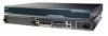
5-1 shows the front view of IPS-4240 and IPS-4255. Figure 5-1 IPS-4240/IPS-4255 Front Panel Features PWR STATUS FLASH Cisco IPS 4240 series Intrusion Prevention Sensor 114003 Power Flash Status Table 5-1 describes the front panel indicators on IPS-4240 and IPS-4255. Table 5-1 Front Panel - Cisco IPS-4240-K9 | User Guide - Page 105
5 Installing IPS-4240 and IPS-4255 Front and Back Panel Features 114002 Figure 5-2 shows the back view of the IPS-4240 and IPS-4255. Figure 5-2 IPS-4240 and IPS-4255 Back Panel Features GigabitEthernet0/0 External compact Serial Management0/0 flash device console (not used) port Power - Cisco IPS-4240-K9 | User Guide - Page 106
Chapter 5 Installing IPS-4240 and IPS-4255 Specifications Table 5-3 lists the specifications for IPS-4240 and IPS-4255. Table 5-3 IPS-4240 and IPS-4255 Specifications Dimensions and Weight Height 1.75 in. (4.45 cm) Width 17.5 in. (44.45 cm) Depth 14.5 in. (36.83 cm) Weight 20.0 lb - Cisco IPS-4240-K9 | User Guide - Page 107
. Statement 1030 IPS-4240 and IPS-4255 accessories kit contains the following: • DB25 connector • DB9 connector • Rack mounting kit-screws, washers, and metal bracket • RJ45 console cable • Two 6-ft Ethernet cables 78-16124-01 Installing Cisco Intrusion Prevention System Appliances and Modules - Cisco IPS-4240-K9 | User Guide - Page 108
Psreevrieenstion Sensor 114016 Note The top hole on the left bracket is a banana jack you can use for ESD grounding purposes when you are servicing the system. You can use the two threaded holes to mount a ground lug to ground the chassis. Installing Cisco Intrusion Prevention System Appliances - Cisco IPS-4240-K9 | User Guide - Page 109
or service this equipment. Statement 1030 Caution Follow proper safety procedures when performing these steps by reading the safety warnings in Regulatory Compliance and Safety Information for the Cisco Intrusion Prevention System 4200 Series Appliance Sensor. To install IPS-4240 and IPS-4255 on - Cisco IPS-4240-K9 | User Guide - Page 110
/0, GigabitEthernet0/1, GigabitEthernet0/2, and GigabitEthernet0/3 (from right to left) are sensing ports. • Management0/0 is the command and control port. Power on the appliance. Initialize the appliance. Installing Cisco Intrusion Prevention System Appliances and Modules 5.0 5-8 78-16124-01 - Cisco IPS-4240-K9 | User Guide - Page 111
-4240 and IPS-4255 Installing IPS-4240 and IPS-4255 Step 9 For the procedure, see Initializing the Sensor, page 9-2. Upgrade the appliance with the most recent Cisco IPS software. For the procedure, see Obtaining Cisco IPS Software, page 10-1. You are now ready to configure intrusion prevention - Cisco IPS-4240-K9 | User Guide - Page 112
Installing IPS-4240 and IPS-4255 Chapter 5 Installing IPS-4240 and IPS-4255 5-10 Installing Cisco Intrusion Prevention System Appliances and Modules 5.0 78-16124-01 - Cisco IPS-4240-K9 | User Guide - Page 113
maximum Memory Specifications Table 6-2 lists the memory specifications for AIP-SSM. Table 6-2 AIP-SSM Memory Specifications Model AIP-SSM-10 AIP-SSM-20 CPU 2.0 GHz Celeron 2.4 GHz Pentium 4 DRAM 1.0 GB 2.0 GB 78-16124-01 Installing Cisco Intrusion Prevention System Appliances and Modules - Cisco IPS-4240-K9 | User Guide - Page 114
) Description The system has power. The system is booting. The system has passed power-up diagnostics. There is Ethernet link. There is Ethernet activity. There is network activity. There is network activity. Installing Cisco Intrusion Prevention System Appliances and Modules 5.0 6-2 78 - Cisco IPS-4240-K9 | User Guide - Page 115
USB2 USB1 119642 LINK 3 SPD LINK 2 SPD LINK 1 SPD LINK 0 SPD FLASH POWER STATUS ACTIVE VPN FLASH Step 4 Insert AIP-SSM through the slot opening. MGMT USB2 see Initializing the Sensor, page 9-2. 78-16124-01 Installing Cisco Intrusion Prevention System Appliances and Modules 5.0 6-3 - Cisco IPS-4240-K9 | User Guide - Page 116
to IDM. • For the procedures for configuring intrusion prevention on your sensor, refer to the following documents: - Installing and Using Cisco Intrusion Prevention System Device Manager 5.0 - Configuring the Cisco Intrusion Prevention System Sensor Using the Command Line Interface 5.0 Verifying - Cisco IPS-4240-K9 | User Guide - Page 117
properly installed, the POWER indicator is solid green and the STATUS indicator is flashing green. Or you can verify installation using the show module command. For the procedure, see Verifying the Status of AIP-SSM, page 6-4. 78-16124-01 Installing Cisco Intrusion Prevention System Appliances and - Cisco IPS-4240-K9 | User Guide - Page 118
Installation and Removal Instructions Chapter 6 Installing AIP-SSM Installing Cisco Intrusion Prevention System Appliances and Modules 5.0 6-6 78-16124-01 - Cisco IPS-4240-K9 | User Guide - Page 119
contains the following sections: • Specifications, page 7-1 • Software and Hardware Requirements, page 7-2 • Supported IDSM-2 Configurations, page 7-2 • Using the TCP Reset Interface, page 7-3 • Front Panel Features, page 7-3 • Installation and Removal Instructions, page 7-4 • Enabling Full Memory - Cisco IPS-4240-K9 | User Guide - Page 120
IDSM-2 cannot block with Cisco IOS-style VACLs. Caution The Supervisor 1A with PFC2 combination is not supported. Supervisor 2 alone (without PFC2 or MSFC2) is not supported by Catalyst software or Cisco IOS software. Installing Cisco Intrusion Prevention System Appliances and Modules 5.0 7-2 78 - Cisco IPS-4240-K9 | User Guide - Page 121
completely. Removing the module without going through a shutdown procedure can corrupt the application partition on the module and result in data loss. 78-16124-01 Installing Cisco Intrusion Prevention System Appliances and Modules 5.0 7-3 - Cisco IPS-4240-K9 | User Guide - Page 122
allowed to install, replace, or service this equipment. Statement 1030 Slot Assignments Note The Catalyst 6509-NEB switch has vertical slots numbered 1 to 9 from right to left. Install IDSM-2 with the component side facing to the right. Installing Cisco Intrusion Prevention System Appliances and - Cisco IPS-4240-K9 | User Guide - Page 123
information about which slots are reserved for the supervisor engine or other modules. Step 3 Remove the installation screws (use a screwdriver, if necessary) that secure the filler plate to the desired slot. 78-16124-01 Installing Cisco Intrusion Prevention System Appliances and Modules 5.0 7-5 - Cisco IPS-4240-K9 | User Guide - Page 124
11 12 13 14 15 16 17 18 19 20 21 22 23 24 24 PORT 100FX LINK LINK LINK LINK LINK LINK LINK LINK LINK LINK LINK LINK LINK LINK to support it. Caution Do not touch the printed circuit boards or connector pins on IDSM-2. Installing Cisco Intrusion Prevention System Appliances and - Cisco IPS-4240-K9 | User Guide - Page 125
19 20 21 22 23 24 24 PORT 100FX LINK LINK LINK LINK LINK installation screws Step 8 Using the thumb and forefinger of each hand, simultaneously pivot in both ejector levers to fully seat IDSM-2 in the backplane connector. 78-16124-01 Installing Cisco Intrusion Prevention System Appliances - Cisco IPS-4240-K9 | User Guide - Page 126
- Configuring the Cisco Intrusion Prevention System Sensor Using the Command Line Interface 5.0 Verifying Installation Verify that the switch acknowledges IDSM-2 and has brought it online. To verify the installation, follow these steps: Step 1 Step 2 Log in to the console. For Catalyst software - Cisco IPS-4240-K9 | User Guide - Page 127
. 2.0 cat6k> (enable) Step 3 For Cisco IOS software: router# show module Mod Ports Card Type Model Serial No. 1 48 48 port 10/100 mb RJ-45 ethernet WS-X6248-RJ board WS-SVC-IDSUPG . 2.0 Ok 78-16124-01 Installing Cisco Intrusion Prevention System Appliances and Modules 5.0 7-9 - Cisco IPS-4240-K9 | User Guide - Page 128
the IDSM-2 CLI and enter reset powerdown. Note The reset powerdown command performs a shut down but does not remove power from IDSM-2. To remove power from IDSM-2, use the set module power down module_number command. 7-10 Installing Cisco Intrusion Prevention System Appliances and Modules 5.0 78 - Cisco IPS-4240-K9 | User Guide - Page 129
1029 78-16124-01 For More Information • For more information on ESD-controlled environments, see Site and Safety Guidelines, page 1-17. • For the procedure for resetting IDSM-2, see Resetting IDSM-2, page 7-13. Installing Cisco Intrusion Prevention System Appliances and Modules 5.0 7-11 - Cisco IPS-4240-K9 | User Guide - Page 130
. console> (enable) The set boot device command can either contain cf:1 or hdd:1. Reset IDSM-2. The full memory test runs. Note A full memory test takes more time to complete than a partial memory test. 7-12 Installing Cisco Intrusion Prevention System Appliances and Modules 5.0 78-16124-01 - Cisco IPS-4240-K9 | User Guide - Page 131
Step 1 Step 2 Step 3 Log in to the console. Enter privileged mode: console> enable Reset IDSM-2 to the application partition or the maintenance partition: console> (enable) reset module_number [hdd:1 | cf:1] 78-16124-01 Installing Cisco Intrusion Prevention System Appliances and Modules 5.0 7-13 - Cisco IPS-4240-K9 | User Guide - Page 132
device variable. Example: router# hw-module module 8 reset Device BOOT variable for reset = Warning: Device list is not verified. Proceed with reload of module? [confirm] % reset issued for module 8 router# 7-14 Installing Cisco Intrusion Prevention System Appliances and Modules 5.0 78-16124-01 - Cisco IPS-4240-K9 | User Guide - Page 133
the switch CLI, follow these steps: Step 1 Step 2 Step 3 Log in to the console. Enter configure terminal mode: router# configure terminal Power up IDSM-2: router(config)# power enable module module_number 78-16124-01 Installing Cisco Intrusion Prevention System Appliances and Modules 5.0 7-15 - Cisco IPS-4240-K9 | User Guide - Page 134
Powering IDSM-2 Up and Down Step 4 Power down IDSM-2: router(config)# no power enable module module_number Chapter 7 Installing IDSM-2 7-16 Installing Cisco Intrusion Prevention System Appliances and Modules 5.0 78-16124-01 - Cisco IPS-4240-K9 | User Guide - Page 135
Chapter 7 Installing IDSM-2 Powering IDSM-2 Up and Down 78-16124-01 Installing Cisco Intrusion Prevention System Appliances and Modules 5.0 7-17 - Cisco IPS-4240-K9 | User Guide - Page 136
install and remove it. Note In Cisco IOS documentation, NM-CIDS is referred to as the Cisco IDS network module. Note NM-CIDS does not support inline (IPS) mode. It can only be configured for promiscuous (IDS) mode. This chapter contains the following sections: • Specifications, page 8-1 • Software - Cisco IPS-4240-K9 | User Guide - Page 137
Cisco 2600XM series Cisco 2691 Cisco 3620 Cisco 3631 Cisco 3640, Cisco 3640A Cisco 3660 Cisco 3725 Cisco 3745 NM-CIDS No Yes Yes No No No Yes Yes Yes Note The supported Cisco series routers only support one NM-CIDS per chassis. 78-16124-01 Installing Cisco Intrusion Prevention System Appliances - Cisco IPS-4240-K9 | User Guide - Page 138
Chapter 8 Installing NM-CIDS Table 8-3 lists the hardware specifications for NM-CIDS. Table 8-3 Hardware Requirements Feature Processor Default SDRAM Maximum DSRAM NM-CIDS Fast Ethernet 0 119517 Installing Cisco Intrusion Prevention System Appliances and Modules 5.0 8-3 78-16124-01 - Cisco IPS-4240-K9 | User Guide - Page 139
can become vulnerable to attacks. For the procedure for assigning the IP address to gain access to the console and for setting up a loopback address, refer to Configuring Cisco IDS Interfaces on the Router. 78-16124-01 Installing Cisco Intrusion Prevention System Appliances and Modules 5.0 8-4 - Cisco IPS-4240-K9 | User Guide - Page 140
NM-CIDS This section describes how to install NM-CIDS off line and using OIR support, and contains the following topics: • Installing NM-CIDS Offline, page 8-6 • Installing NM-CIDS Using OIR Support, page 8-8 Installing Cisco Intrusion Prevention System Appliances and Modules 5.0 8-5 78-16124-01 - Cisco IPS-4240-K9 | User Guide - Page 141
procedures, ensure that power is removed from the DC circuit. To ensure that all power is OFF, locate the circuit breaker on the panel board that services the DC circuit, switch or flat-blade screwdriver. 78-16124-01 Installing Cisco Intrusion Prevention System Appliances and Modules 5.0 8-6 - Cisco IPS-4240-K9 | User Guide - Page 142
intrusion prevention on your sensor, refer to the following documents: - Installing and Using Cisco Intrusion Prevention System Device Manager 5.0 - Configuring the Cisco Intrusion Prevention System Sensor Using the Command Line Interface 5.0 Installing Cisco Intrusion Prevention System Appliances - Cisco IPS-4240-K9 | User Guide - Page 143
indicators light up, and that the Active/Ready indicators on the front panel also light up. Initialize NM-CIDS. For the procedure, see Initializing the Sensor, page 9-2. 78-16124-01 Installing Cisco Intrusion Prevention System Appliances and Modules 5.0 8-8 - Cisco IPS-4240-K9 | User Guide - Page 144
following documents: - Installing and Using Cisco Intrusion Prevention System Device Manager 5.0 - Configuring the Cisco Intrusion Prevention System Sensor Using the Command Line Interface 5.0 Removing NM-CIDS This section describes how to remove NM-CIDS offline or using OIR support, and contains - Cisco IPS-4240-K9 | User Guide - Page 145
Open Wait for the shutdown message before continuing with Step 2: %SERVICEMODULE-5-SHUTDOWN2:Service module IDS-Sensor1/0 shutdown complete Unplug the command and control network interface cable from NM-CIDS. 78-16124-01 Installing Cisco Intrusion Prevention System Appliances and Modules 5.0 8-10 - Cisco IPS-4240-K9 | User Guide - Page 146
router is not fully configured with network modules, make sure that blank panels fill the unoccupied chassis slots to provide proper airflow as shown in Figure 8-3. Figure 8-3 Blank Network Module Panel 1 1 H6552 8-11 Installing Cisco Intrusion Prevention System Appliances and Modules 5.0 78 - Cisco IPS-4240-K9 | User Guide - Page 147
to use this configuration. If you type yes, the configuration is saved. If you type no, the configuration is not saved and the process begins again. There is no default for this prompt; you must type either yes or no. 78-16124-01 Installing Cisco Intrusion Prevention System Appliances and Modules - Cisco IPS-4240-K9 | User Guide - Page 148
in and assign a new password to the user who forgot the password. Or, if you have created the service account for support purposes, you can have TAC create a password. For more information, refer to Creating the Service Account. Installing Cisco Intrusion Prevention System Appliances and Modules - Cisco IPS-4240-K9 | User Guide - Page 149
continue. Specify the hostname. The hostname is a case-sensitive character string up to 64 characters. Numbers, "_" and "-" are valid, but spaces are not acceptable. The default is sensor. 78-16124-01 Installing Cisco Intrusion Prevention System Appliances and Modules 5.0 9-3 - Cisco IPS-4240-K9 | User Guide - Page 150
also known as DST. If your location does not use Summertime, go to Step n. c. Choose recurring, date, or disable to specify how you want to configure summertime settings. The default is recurring. Installing Cisco Intrusion Prevention System Appliances and Modules 5.0 9-4 78-16124-01 - Cisco IPS-4240-K9 | User Guide - Page 151
). The default is 0. n. Type yes to modify the system time zone. o. Specify the standard time zone name. The zone name is a character string up to 24 characters long. p. Specify the standard time offset. The default is 0. 78-16124-01 Installing Cisco Intrusion Prevention System Appliances and - Cisco IPS-4240-K9 | User Guide - Page 152
X.509 certificate (needed by TLS): sensor# show tls fingerprint MD5: C4:BC:F2:92:C2:E2:4D:EB:92:0F:E4:86:53:6A:C6:01 SHA1: 64:9B:AC:DE:21:62:0C:D3:57:2E:9B:E5:3D:04:8F:A7:FD:CD:6F:27 Installing Cisco Intrusion Prevention System Appliances and Modules 5.0 9-6 78-16124 - Cisco IPS-4240-K9 | User Guide - Page 153
the most recent service pack and signature update. For information on how to obtain the most recent software, see Obtaining Cisco IPS Software, page 10-1. The Readme explains how to apply the most recent software update. You are now ready to configure your sensor for intrusion prevention. For More - Cisco IPS-4240-K9 | User Guide - Page 154
:A7:FD:CD:6F:27 Write down the certificate fingerprints. You will need these to check the authenticity of the certificate when connecting to this sensor with a web browser. Installing Cisco Intrusion Prevention System Appliances and Modules 5.0 9-8 78-16124-01 - Cisco IPS-4240-K9 | User Guide - Page 155
signature updates. To download software on Cisco.com, follow these steps: Step 1 Step 2 Step 3 Log in to Cisco.com. From the Support drop-down menu, choose Download Software. Under Select a Software Product Category, choose Security Software. 78-16124-01 Installing Cisco Intrusion Prevention - Cisco IPS-4240-K9 | User Guide - Page 156
your computer. Follow the instructions in the Readme to install the update. Note Major and minor updates, service packs, recovery files, signature and signature engine updates are the same for all sensors. System image files are unique per platform. IPS Software Versioning This section describes - Cisco IPS-4240-K9 | User Guide - Page 157
upgrades contain all previous minor features, service pack fixes, and signature updates since the last major version, and the new minor features being released. The minor upgrade requires the major version. 78-16124-01 Installing Cisco Intrusion Prevention System Appliances and Modules 5.0 10-3 - Cisco IPS-4240-K9 | User Guide - Page 158
on how to install the files. For instructions on how to access these files on Cisco.com, see Obtaining Cisco IPS Software, page 10-1. Table 10-1 Platform-Independent Release Examples Release Signature update1 Service pack2 Minor version3 Major version4 Supported Target Frequency Identifier - Cisco IPS-4240-K9 | User Guide - Page 159
to Upgrading the Sensor. If you configured Auto Update for your sensor, copy the 5.0 upgrade file to the directory on the server that your sensor polls for updates. Refer to Configuring Automatic Upgrades. 78-16124-01 Installing Cisco Intrusion Prevention System Appliances and Modules 5.0 10 - Cisco IPS-4240-K9 | User Guide - Page 160
IPS Products, page 10-7. Trial license keys are also available. If you cannot get your sensor licensed because of problems with your contract, you can obtain a 60-day trial license that supports signature updates that require licensing. 10-6 Installing Cisco Intrusion Prevention System Appliances - Cisco IPS-4240-K9 | User Guide - Page 161
IPS, you must purchase a SMARTnet contract: Note SMARTnet provides operating system updates, access to Cisco.com, access to TAC, and hardware replacement NBD on site. • ASA5510-K8 • ASA5510-DC-K8 • ASA5510-SEC-BUN-K9 • ASA5520-K8 78-16124-01 Installing Cisco Intrusion Prevention System Appliances - Cisco IPS-4240-K9 | User Guide - Page 162
with administrator privileges. Choose Configuration > Licensing. The Licensing pane displays the status of the current license. If you have already installed your license, you can click Download to save it if needed. 10-8 Installing Cisco Intrusion Prevention System Appliances and Modules 5.0 78 - Cisco IPS-4240-K9 | User Guide - Page 163
. • destination-url-The location of the destination file to be copied. It can be a URL or a keyword. • license-key-The subscription license file. • license_file_name-The name of the license file you receive. 78-16124-01 Installing Cisco Intrusion Prevention System Appliances and Modules 5.0 10-9 - Cisco IPS-4240-K9 | User Guide - Page 164
be sent by e-mail to the e-mail address you specified. Save the license key to a system that has a web server, FTP server, or SCP server. Log in to the CLI using an account with administrator privileges. 10-10 Installing Cisco Intrusion Prevention System Appliances and Modules 5.0 78-16124-01 - Cisco IPS-4240-K9 | User Guide - Page 165
Software Cisco IPS Active Update Bulletins Step 5 Copy the license key to the sensor: sensor# copy scp://[email protected]://tftpboot/dev.lic license-key Password: ******* Step 6 Verify the sensor is licensed: sensor# show version Application Partition: Cisco Intrusion Prevention System - Cisco IPS-4240-K9 | User Guide - Page 166
-Takes you to the software download site. • Reference Guides-Contains command references. • Design-Contains design guide and tech notes. • Install and Upgrade-Contains hardware installation and regulatory guides. 10-12 Installing Cisco Intrusion Prevention System Appliances and Modules 5.0 78 - Cisco IPS-4240-K9 | User Guide - Page 167
of information for individual signatures, including signature ID, type, structure, and description. You can access the signature search at this URL: http://tools.cisco.com/MySDN/Intelligence/searchSignatures.x 78-16124-01 Installing Cisco Intrusion Prevention System Appliances and Modules 5.0 10 - Cisco IPS-4240-K9 | User Guide - Page 168
Cisco Security Center Chapter 10 Obtaining Software 10-14 Installing Cisco Intrusion Prevention System Appliances and Modules 5.0 78-16124-01 - Cisco IPS-4240-K9 | User Guide - Page 169
. Specifically, an IPS event type; it is written to the Event Store as an evidsAlert. In general, an alert is an IPS message that indicates a network exploit in progress or a potential security problem occurrence. Also known as an alarm. 78-16124-01 Installing Cisco Intrusion Prevention System - Cisco IPS-4240-K9 | User Guide - Page 170
the power distribution buses inside a chassis. A software release that must be installed before a follow-up release such as a service pack or signature update can be installed. Major and minor version upgrades are base version releases. GL-2 Installing Cisco Intrusion Prevention System Appliances - Cisco IPS-4240-K9 | User Guide - Page 171
with the sensor used for configuring and controlling the sensor applications. The interface on the sensor that communicates with the IPS manager and other network devices. This interface has an assigned IP address. 78-16124-01 Installing Cisco Intrusion Prevention System Appliances and Modules - Cisco IPS-4240-K9 | User Guide - Page 172
Address of a network device that is receiving data. DFP Deny Filters Processor. Handles the deny attacker functions. It maintains a list of denied source IP addresses. DIMM. Dual In-line Memory Modules. GL-4 Installing Cisco Intrusion Prevention System Appliances and Modules 5.0 78-16124-01 - Cisco IPS-4240-K9 | User Guide - Page 173
to the Event Store that represents an alert. F false negative false positive A signature is not fired when offending traffic is detected. Normal traffic or a benign action causes a signature to fire. 78-16124-01 Installing Cisco Intrusion Prevention System Appliances and Modules 5.0 GL-5 - Cisco IPS-4240-K9 | User Guide - Page 174
.3 specification. Router support the original size of the packet. See FRP. Fragment Reassembly Processor. Reassembles fragmented IP datagrams. It is also responsible for normalization of IP fragments when the sensor Installing Cisco Intrusion Prevention System Appliances and Modules 5.0 78-16124-01 - Cisco IPS-4240-K9 | User Guide - Page 175
application that lets you configure and manage your sensor. The web server for IDM resides on the sensor. You can access it through Netscape or Internet Explorer web browsers. IPS Intrusion Prevention System. A system that alerts the user to the presence of an intrusion on the network through - Cisco IPS-4240-K9 | User Guide - Page 176
of individual IP session information. Remote access, back door Trojan, ICMP tunneling software. When the computer is infected, the malicious code creates an ICMP tunnel that can be used to send small payload ICMP replies GL-8 Installing Cisco Intrusion Prevention System Appliances and Modules - Cisco IPS-4240-K9 | User Guide - Page 177
NM-CIDS are IPS modules. See sensing interface. Multilayer Switch Feature Card. An optional card on a Catalyst 6000 supervisor engine that performs L3 routing for the switch. Microsoft Remote Procedure Call. 78-16124-01 Installing Cisco Intrusion Prevention System Appliances and Modules 5.0 GL - Cisco IPS-4240-K9 | User Guide - Page 178
insertion and removal. Feature that permits you to add, replace, or remove cards without interrupting the system power, entering console commands, or causing other software or interfaces to shutdown. GL-10 Installing Cisco Intrusion Prevention System Appliances and Modules 5.0 78-16124-01 - Cisco IPS-4240-K9 | User Guide - Page 179
ACL entries, and where it places entries after all deny entries for the addresses being blocked. Power-On Self Test. Set of hardware diagnostics that runs on a hardware device when that device is powered up. 78-16124-01 Installing Cisco Intrusion Prevention System Appliances and Modules 5.0 GL-11 - Cisco IPS-4240-K9 | User Guide - Page 180
of the risk associated with a particular event on the network. RSM Router Switch Module. A router module that is installed in a Catalyst 5000 switch. It functions exactly like a standalone router. GL-12 Installing Cisco Intrusion Prevention System Appliances and Modules 5.0 78-16124-01 - Cisco IPS-4240-K9 | User Guide - Page 181
. Packets flow through a pipeline of processors fed by a producer designed to collect packets from the network interfaces on the sensor. Sensorapp is the standalone executable that runs Analysis Engine. 78-16124-01 Installing Cisco Intrusion Prevention System Appliances and Modules 5.0 GL-13 - Cisco IPS-4240-K9 | User Guide - Page 182
management protocol used almost exclusively in TCP/IP networks. SNMP provides a means to monitor and control network devices, and to manage configurations, statistics collection, performance, and security. GL-14 Installing Cisco Intrusion Prevention System Appliances and Modules 5.0 78-16124-01 - Cisco IPS-4240-K9 | User Guide - Page 183
a general signature. It typically further defines a broad scope signature. surface mounting Refers to attaching rubber feet to the bottom of a sensor when it is installed on a flat layer of the OSI model. 78-16124-01 Installing Cisco Intrusion Prevention System Appliances and Modules 5.0 GL-15 - Cisco IPS-4240-K9 | User Guide - Page 184
as port 1 with Catalyst software, and is not visible to the user in Cisco IOS software. The TCP reset action is only appropriate as an action selection on those signatures that are associated with a TCP-based service. Telnet Standard terminal emulation protocol in the TCP/IP protocol stack - Cisco IPS-4240-K9 | User Guide - Page 185
to modify an existing signature. U UDI Unique Device Identifier. Provides a unique identity for every Cisco product. The UDI is composed of the PID, VID, and SN. The UDI is stored in the Cisco IPS ID PROM. 78-16124-01 Installing Cisco Intrusion Prevention System Appliances and Modules 5.0 GL - Cisco IPS-4240-K9 | User Guide - Page 186
to them. In other words, multiple virtual sensors running on the same appliance, each configured with different signature behavior and traffic feeds. IPS 5.x supports only one virtual sensor. Hidden, self-replicating section of computer software, usually malicious logic, that propagates by infecting - Cisco IPS-4240-K9 | User Guide - Page 187
and X.25 are examples of WANs. A component of the IPS. Wireshark is a free network protocol analyzer for UNIX and Windows information for each packet. Wireshark has several powerful features, including a rich display filter language Installing Cisco Intrusion Prevention System Appliances and Modules - Cisco IPS-4240-K9 | User Guide - Page 188
Glossary GL-20 Installing Cisco Intrusion Prevention System Appliances and Modules 5.0 78-16124-01 - Cisco IPS-4240-K9 | User Guide - Page 189
surface mounting 3-5 IDS-4235 front panel 4-2 indicators 4-3 IDS-4250 front panel 4-2 indicators 4-3 installing XL cards 4-13 managers 1-8 models 1-8 restrictions 1-9 setting up a terminal server 1-9 SPAN 1-8 78-16124-01 Installing Cisco Intrusion Prevention System Appliances and Modules 5.0 IN-1 - Cisco IPS-4240-K9 | User Guide - Page 190
software 10-1 downloading software updates 10-6 IPS software 10-1 software downloads 10-1 Cisco.com account 10-6 Cisco IOS software IDSM-2 enabling full memory tests 7-13 resetting 7-14 Cisco Security Center described 10-13 URL 10-13 Cisco Services for IPS service contract 10-7 supported - Cisco IPS-4240-K9 | User Guide - Page 191
3-16 installing 3-7 rack mounting 3-6 ROMMON upgrade 3-9 specifications 3-3 surface installing 4-10 removing 4-10 described 4-1 front panel (figure) 4-2 indicators 4-2 installing power supply 4-10 procedure 4-7 SCSI hard-disk drives 4-17 Installing Cisco Intrusion Prevention System Appliances - Cisco IPS-4240-K9 | User Guide - Page 192
(Catalyst OS) 7-15 powering up (Cisco IOS) 7-15 removing 7-10 requirements 7-2 resetting Catalyst software 7-13 Cisco IOS software 7-14 shutdown button 7-3 command 7-3 described 7-10 slot assignments 7-5 SPAN 1-12 specifications 7-1 status indicator 7-3 supported configurations 7-2 time sources 1-14 - Cisco IPS-4240-K9 | User Guide - Page 193
8-6 power supply 4-10 SCSI hard-disk drives 4-17 sensor license 10-8 SX card 4-12 XL cards 4-13 interface support (table) 1-5 IPS-4240 accessories 5-5 back panel figure 5-3 indicators 5-3 described 5-1 features 5-2 front panel figure 5-2 indicators 5-2 installing 5-7 rack mounting 5-6 specifications - Cisco IPS-4240-K9 | User Guide - Page 194
IPS mode 1-1 license 10-8 models 1-6 network topology 1-6 NTP time synchronization 1-14 power supply guidelines 1-19 preparing for installation 1-16 rack configuration guidelines 1-18 recovering the system image 10-6 reimaging 10-6 setup command 9-1, 9-2 site guidelines 1-17 supported 1-6 TCP reset - Cisco IPS-4240-K9 | User Guide - Page 195
10-13 using TCP reset interface 1-4 Index V VLAN access control list see VACLs VACLs IDSM-2 1-12 verifying IDSM-2 installation 7-8 sensor initialization 9-7 sensor setup 9-7 X XL cards fiber ports 4-14 installing 4-13 78-16124-01 Installing Cisco Intrusion Prevention System Appliances and Modules - Cisco IPS-4240-K9 | User Guide - Page 196
Index IN-8 Installing Cisco Intrusion Prevention System Appliances and Modules 5.0 78-16124-01
-
 1
1 -
 2
2 -
 3
3 -
 4
4 -
 5
5 -
 6
6 -
 7
7 -
8
-
9
-
10
-
11
-
12
-
13
-
14
-
15
-
16
-
17
-
18
-
19
-
20
-
21
-
22
-
23
-
24
-
25
-
26
-
27
-
28
-
29
-
30
-
31
-
32
-
33
-
34
-
35
-
36
-
37
-
38
-
39
-
40
-
41
-
42
-
43
-
44
-
45
-
46
-
47
-
48
-
49
-
50
-
51
-
52
-
53
-
54
-
55
-
56
-
57
-
58
-
59
-
60
-
61
-
62
-
63
-
64
-
65
-
66
-
67
-
68
-
69
-
70
-
71
-
72
-
73
-
74
-
75
-
76
-
77
-
78
-
79
-
80
-
81
-
82
-
83
-
84
-
85
-
86
-
87
-
88
-
89
-
90
-
91
-
92
-
93
-
94
-
95
-
96
-
97
-
98
-
99
-
100
-
101
-
102
-
103
-
104
-
105
-
106
-
107
-
108
-
109
-
110
-
111
-
112
-
113
-
114
-
115
-
116
-
117
-
118
-
119
-
120
-
121
-
122
-
123
-
124
-
125
-
126
-
127
-
128
-
129
-
130
-
131
-
132
-
133
-
134
-
135
-
136
-
137
-
138
-
139
-
140
-
141
-
142
-
143
-
144
-
145
-
146
-
147
-
148
-
149
-
150
-
151
-
152
-
153
-
154
-
155
-
156
-
157
-
158
-
159
-
160
-
161
-
162
-
163
-
164
-
165
-
166
-
167
-
168
-
169
-
170
-
171
-
172
-
173
-
174
-
175
-
176
-
177
-
178
-
179
-
180
-
181
-
182
-
183
-
184
-
185
-
186
-
187
-
188
-
189
-
190
-
191
-
192
-
193
-
194
-
195
-
196
 |
 |

Americas Headquarters
Cisco Systems, Inc.
170 West Tasman Drive
San Jose, CA 95134-1706
USA
Tel: 408 526-4000
800 553-NETS (6387)
Fax: 408 527-0883
Installing Cisco Intrusion Prevention
System Appliances and Modules 5.0
Customer Order Number: DOC=7816124
Text Part Number: 78-16124-01