Cobra PRO 2500W PRO 2500W Manual
Cobra PRO 2500W Manual
 |
View all Cobra PRO 2500W manuals
Add to My Manuals
Save this manual to your list of manuals |
Cobra PRO 2500W manual content summary:
- Cobra PRO 2500W | PRO 2500W Manual - Page 1
1|Page ©2020 Cobra Electronics Corporation Version A - Cobra PRO 2500W | PRO 2500W Manual - Page 2
12 PRO 1500W INSTALLATION INSTRUCTIONS 13 PRO 2500W & 3000W INSTALLATION INSTRUCTIONS 16 TURNING YOUR INVERTER ON AND OFF 19 CHANGING THE LOW VOLTAGE ALARM SETTING 20 COBRA REMOTE ON/OFF CONTROLLER WITH FAST CHARGE USB 21 OPERATING INDICATORS ...22 OPERATING LIMITS...23 TROUBLESHOOTING GUIDE - Cobra PRO 2500W | PRO 2500W Manual - Page 3
. If your product should require factory service, please go to www.cobra.com/support and follow the instructions. WHAT'S IN THE BOX • PRO Power Inverter (1500W, 2500W or 3000W) • (2) 48-inch #4AWG Power Cables (PRO 1500W) • (4) 48-inch #4AWG Power Cables (PRO 2500W) • (4) 48-inch #2AWG Power Cables - Cobra PRO 2500W | PRO 2500W Manual - Page 4
CONTROLS AND CONNECTIONS PRO 1500W Features 4|Page - Cobra PRO 2500W | PRO 2500W Manual - Page 5
in kilowatts (kW), Power in Watts (W) and Error Codes I. USB-C Fast Charge port (5V/9V/15W)* J. USB-A Fast Charge port (5V/9V/15W)* K. Port for Cobra Remote On/Off Controller with Fast Charge USB (Sold Separately)* L Power Button M. Power Cables N. Inverter Terminal Protector Boots - Cobra PRO 2500W | PRO 2500W Manual - Page 6
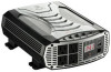
PRO 2500W and 3000W Features 6|Page - Cobra PRO 2500W | PRO 2500W Manual - Page 7
Separately)* L Power Button M. Power Cables N. Inverter Terminal Protector Boots O. Cobra Remote On/Off Controller with Fast Charge USB (Sold Separately)* *Included with PRO 3000W/Sold Separately from PRO 2500W ** = Fast Charge works only on devices capable of supporting a charge up to 10W 7|Page - Cobra PRO 2500W | PRO 2500W Manual - Page 8
Cobra power inverter, please read these general precautions and warnings. Caution and Warning Statements Special attention must be paid to the CAUTION and WARNING statements in the manual inverter; it contains no user-serviceable parts. Attempting to service unit could cause electrical shock. NOTE - Cobra PRO 2500W | PRO 2500W Manual - Page 9
DC output (less than 30 volts), the inverter will have no problem powering the adapter safely. Cobra PRO Output Waveform Some very sensitive electronic equipment may not operate satisfactory on . For detailed specifications go to Specifications section of this manual, starting on page 25. 9|Page - Cobra PRO 2500W | PRO 2500W Manual - Page 10
AC appliance or device by 10. 2. Cables to connect your inverter to the vehicle battery. These come with your PRO Inverter and provide a length of 48". DETERMINING THE POWER REQUIREMENTS FOR YOUR PRO INVERTER Before you turn on your power inverter and plug in an appliance or device, you will want to - Cobra PRO 2500W | PRO 2500W Manual - Page 11
the continuous AC load Wattage by 10. For example, the continuous load of the PRO 3000W Power Inverter is 3000 Watts. The current (Amps) is: 3000/10 of mounting hardware. Use only corrosive resistant screws (not included) Mounting Instructions: 1. Make sure the inverter is OFF. 2. Check for wires, - Cobra PRO 2500W | PRO 2500W Manual - Page 12
from ring terminal and install fuse. Use (1) 150 Amp ANL fuse or equivalent for the PRO 1500W, (2) 150 Amp ANL fuses or equivalent for the PRO 2500W, or (2) ANL 200 Amp ANL fuses or equivalent for the PRO 3000W power inverter. Do not use aluminum wire. Aluminum has about one-third more resistance - Cobra PRO 2500W | PRO 2500W Manual - Page 13
PRO 1500W INSTALLATION INSTRUCTIONS: These instructions are specific for Negative Ground 12 Volt Systems. In from ring terminal and install fuse. Use a 150 Amp ANL fuse or equivalent for the PRO 1500W inverter. 5. Disconnect the battery clamp connector at the negative (-) battery terminal. 6. - Cobra PRO 2500W | PRO 2500W Manual - Page 14
before making this connection. All power connections to your Cobra inverter must be Positive to Positive and Negative to Negative battery as possible. We recommend (1) 150 Amp ANL fuse or equivalent for the PRO 500W power inverter. The specific fuse ampere rating should be sized to allow operation - Cobra PRO 2500W | PRO 2500W Manual - Page 15
PRO 1500W INSTALLATION 15 | P a g e - Cobra PRO 2500W | PRO 2500W Manual - Page 16
PRO 2500W & 3000W INSTALLATION INSTRUCTIONS These instructions are specific for Negative Ground 12 Volt Systems. In fuse. Use (2) 150 Amp ANL fuses or equivalent for PRO 2500W or (2) 200 Amp ANL fuses or equivalent for the PRO 3000W power inverters. 5. Disconnect the battery clamp connector at the - Cobra PRO 2500W | PRO 2500W Manual - Page 17
before making this connection. All power connections to your Cobra inverter must be Positive to Positive and Negative to recommend (2) 150 Amp ANL fuses or equivalent for PRO 2500W or (2) 200 Amp ANL fuses or equivalent for the PRO 3000W power inverter. The specific fuse ampere rating should - Cobra PRO 2500W | PRO 2500W Manual - Page 18
PRO 2500W AND 3000W INSTALLATION 18 | P a g e - Cobra PRO 2500W | PRO 2500W Manual - Page 19
before attempting to turn it on (see page 11). PRO1500W/2500W POWER INVERTER BASIC OPERATION 1. Press the POWER button to turn on your inverter . 2. When powered on the Input Voltage LED is green. PRO 3000W POWER INVERTER BASIC OPERATION 1. Connect the Remote On/Off Controller in the - Cobra PRO 2500W | PRO 2500W Manual - Page 20
Voltage Alarm setting for professional trucks. If using a Cobra Pro Power Inverter with other vehicle types such as a car, van or RV, run time can be extended by changing the default Low Voltage Alarm to the alternate setting at 10.5 Volts. Instructions to change the Low Voltage Alarm setting are as - Cobra PRO 2500W | PRO 2500W Manual - Page 21
is included with the Cobra PRO 3000W Power Inverter. All PRO Inverters come equipped with an RJ-45 jack labeled "REMOTE" for compatibility with the Cobra Remote On/Off Controller inverter is out of reach. Operating instructions and details start on page 26. *Sold Separately. Can be purchased on www - Cobra PRO 2500W | PRO 2500W Manual - Page 22
is disabled, an alarm will sound then you will get the following display. To restore to normal inverter operation, first unplug faulty appliance. Then, manually reset the power inverter by turning it OFF then ON. NOTE: Internal inverter temperature can rise due to being operated in a high heat - Cobra PRO 2500W | PRO 2500W Manual - Page 23
OPERATING LIMITS Power Output Your PRO Series power inverter can operate on its full rated output for about 60 minutes. The inverter must cool for 15 minutes before it can resume - Cobra PRO 2500W | PRO 2500W Manual - Page 24
TROUBLESHOOTING GUIDE Problem/Symptom Low output voltage No output voltage No output voltage aŌer prolonged use No output voltage, "Protect" indicator lighted No output voltage No output voltage - Cobra PRO 2500W | PRO 2500W Manual - Page 25
Temperature, Short Circuit, Reverse Polarity, Over/Under Voltage and GFCI PRO 2500W CPI2500W 13.0V DC 115V AC, 60Hz, 21.7A, 2500W Modified Sine Wave (MSW) 2500 Watt 5000 Watt 90% < or debris. Product Service For any questions about operating or installing this new Cobra product, please go to www - Cobra PRO 2500W | PRO 2500W Manual - Page 26
Remote On/Off Controller with Fast Charge USB (Model CPIALCDG1) When used with your Cobra Power Inverter, the Cobra Remote On/Off Controller with Fast Charge USB provides convenience to turn your power inverter on or off from anywhere inside your vehicle and simultaneously - Cobra PRO 2500W | PRO 2500W Manual - Page 27
G. Keyhole Mount H. RJ-45 Remote Control Cable Jack I. RJ-45 Remote Control Cable J. Clip Mont K. M3.5 Screws * = Fast Charge works only on devices capable of supporting a charge up to 10W 27 | P a g e - Cobra PRO 2500W | PRO 2500W Manual - Page 28
4-Point Mounting System Whether you own a standard vehicle, RV, Professional Truck, or Camper, Cobra gives you (4) Mounting options to remotely turn your inverter on and off as well as charge your devices from anywhere in your vehicle: + See Mounting Template on page 34 + 28 | P a g e - Cobra PRO 2500W | PRO 2500W Manual - Page 29
29 | P a g e - Cobra PRO 2500W | PRO 2500W Manual - Page 30
REMOTE DISPLAY MESSAGING Standby Mode When you plug in the Remote On/Off Controller with Fast Charge USB and press the power button to ON, the display will show AC Output (Watts being used) and the DC Input (Battery Volts). The images below show the messaging on the LCD display when the remote is - Cobra PRO 2500W | PRO 2500W Manual - Page 31
DC Input High Voltage Alarm The alarm will sound when the battery is at 15.0V. AC Output Short The alarm will sound and the inverter will shut down when the AC output is shorted. ... AC Output Overload The alarm will sound and the inverter will shut down AC output exceeds the inverter limits. - Cobra PRO 2500W | PRO 2500W Manual - Page 32
to recharge your car battery If none of these solutions fix the problem you are having, please contact Product Service and Support online at www.cobra.com/support or call 1-800-543-1608 SPECIFICATIONS Specifications: COBRA REMOTE ON/OFF CONTROLLER Model CPIALCDG1 USB-A Output Port 5V/2A/10W - Cobra PRO 2500W | PRO 2500W Manual - Page 33
as a duplicated copy of a sales receipt. You must pay any initial shipping charges required to ship the product for warranty service, but the return charges will be at Cobra's expense, if the product is repaired or replaced under warranty. This warranty gives you specific legal rights, and you may - Cobra PRO 2500W | PRO 2500W Manual - Page 34
This template should measure 3.35". Please ensure that this measurement is checked on your print-out for accuracy before making your cuts and installing. 34 | P a g e
-
 1
1 -
 2
2 -
 3
3 -
 4
4 -
 5
5 -
 6
6 -
 7
7 -
8
-
9
-
10
-
11
-
12
-
13
-
14
-
15
-
16
-
17
-
18
-
19
-
20
-
21
-
22
-
23
-
24
-
25
-
26
-
27
-
28
-
29
-
30
-
31
-
32
-
33
-
34
 |
 |

1 |
Page
©2020 Cobra Electronics Corporation
Version A