CyberPower RMCARD400 User Manual
CyberPower RMCARD400 Manual
 |
View all CyberPower RMCARD400 manuals
Add to My Manuals
Save this manual to your list of manuals |
CyberPower RMCARD400 manual content summary:
- CyberPower RMCARD400 | User Manual - Page 1
Manual Remote Management Card RMCARD400 RMCARD401 The Remote Management Card allows a UPS system and environmental sensor to be managed, monitored, and configured. Copyright © 2023 Cyber Power Systems, Inc. All rights reserved. 1 K01-E0000043-00 - CyberPower RMCARD400 | User Manual - Page 2
TABLE OF CONTENTS Introduction ...3 Installation Guide 6 Web Interface ...9 Command Line Interface 35 Reset to Factory Default Setting / Recover from a Lost Password 55 RMCARD Firmware Upgrade 56 Save and Restore Configuration Settings 60 Troubleshooting 63 Conformance Approvals 64 Appendix - CyberPower RMCARD400 | User Manual - Page 3
/v6, SNMPv1/v3, HTTP/HTTPs, TCP/IP, UDP, DHCP, NTP, DNS, SMTP, SMTPS, SSH, Telnet, FTP and Syslog protocol Support Email Secure Authentication Protocols: SSL, TLS Support External Authentication Protocols: RADIUS, LDAP, LDAPS, 802.1X, Windows AD SNMP MIB available for free download User upgradeable - CyberPower RMCARD400 | User Manual - Page 4
Inspect the Remote Management Card upon receipt. The package should contain the following: CyberPower Remote Management Card RJ45/DB9 Serial Port Connection Cable Quick Start Guide Spare Jumper 4 - CyberPower RMCARD400 | User Manual - Page 5
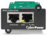
Front Panel RMCARD400 RMCARD400 1 2 Universal Link Tx/Rx 3 4 RMCARD401 2 RMCARD40 1 1 5 Universal Link Tx/R x USB 3 1. Universal Port 2. Ethernet Port 3. Tx/Rx Indicator 4. Link Indicator 5. USB Port 4 LED Status Indicators Link LED Off On (Yellow) On (Green) Tx/Rx LED Off On ( - CyberPower RMCARD400 | User Manual - Page 6
Installation Guide Step 1. Hardware Installation Note: The CyberPower Remote Management Card is hot-swappable, so you do not need to turn off the UPS to install it. - CyberPower RMCARD400 | User Manual - Page 7
Step 2. Configure the IP address for the CyberPower Remote Management Card Note: These instructions are for Windows OS. For other OS please refer to Appendix 4. Method 1: Using the Power Device Network Utility 2 1. Install the Power Device Network Utility available - CyberPower RMCARD400 | User Manual - Page 8
not successful, for example, if the IP address change is unsuccessful you will see a warning message. Attempt to make the desired changes again. If the problem persists, please see the Troubleshooting section for help. 8 - CyberPower RMCARD400 | User Manual - Page 9
current UPS battery capacity. Load Graph of the load of UPS as a percentage of available Watts. Remaining Runtime Length of time the UPS can support its load on battery power. System Data Name The name given to the UPS. Location Location description given to the UPS. Contact The person to - CyberPower RMCARD400 | User Manual - Page 10
Item Envir Data Name Location Recent Device Events Definition The name of the environmental sensor. The location of the environmental sensor. A list of device events that recently occurred. The maximum number of events is 5. [UPS] The following items can be displayed/configured through the UPS - CyberPower RMCARD400 | User Manual - Page 11
Item Non-Critical Load (NCL) Energy Battery Status Charge Mode Charge Check Remaining Capacity Remaining Runtime Voltage System Status Temperature Maintenance Breaker Definition The present status of NCL outlets. Device energy meter reading in units of kWh. *Click "Reset" will clear Energy value to - CyberPower RMCARD400 | User Manual - Page 12
Firmware Version The revision number of the UPS LCD firmware Battery Replacement Date The date that the batteries were last replaced. This must be set manually after the batteries have been replaced or when the unit is first installed. If this date has not been set, it is recommended that it - CyberPower RMCARD400 | User Manual - Page 13
thresholds, the UPS will switch to Normal operation. This mode will significantly increase UPS system efficiency. Determines whether to allow the UPS to enter Manual Bypass Mode. If this option is enabled, the UPS will be forced to enter Bypass Mode. Note: The UPS may automatically enter Bypass Mode - CyberPower RMCARD400 | User Manual - Page 14
to function when the selected condition occurs. Refer to the UPS manual for further information about advanced UPS dry relay functions. The Dry using battery power. (2) Low Battery: The battery capacity is too low to support the connected computers to shut down. (3) Alarm: The UPS is issuing the - CyberPower RMCARD400 | User Manual - Page 15
command is available in Utility Power Failure Mode. It puts the UPS in sleep mode until power is restored. Note: Some UPS models may not support this command. Resets the pending action to turn the UPS off. Turns the UPS on. 15 - CyberPower RMCARD400 | User Manual - Page 16
by the outlet configuration (varies by UPS model). Device Name Device Name assigned to this outlet. Note: Only Critical Outlet Bank switchable UPS support on/off control for the Critical Outlet Bank. [UPS->Diagnostics] The UPS/Diagnostics page provides the ability to verify UPS batteries are in - CyberPower RMCARD400 | User Manual - Page 17
Item Last Test Date Runtime Estimation Definition The date of the most recent battery test. The Runtime Estimation function discharges the UPS batteries from the battery capacity, at the time the estimate is requested, to near zero capacity with the current load. The results of the runtime - CyberPower RMCARD400 | User Manual - Page 18
is on. WoL Lists WoL Remote List When the option with PowerPanel® Remote is enabled, it will list PPB Remote PC IP/MAC here. WoL Manual List Wake on Lan manual list. Note: The PowerPanel® Remote computer's BIOS settings need to support WoL and be configured accordingly. 18 - CyberPower RMCARD400 | User Manual - Page 19
[UPS->PowerPanel® List] Display the Information of the connected PowerPanel® Business. The connection is established by PowerPanel® Business. The listed will be removed if disconnected for 1 hour. Item Definition Configuration Max Remote Shutdown Time The max time that all the connected Remote - CyberPower RMCARD400 | User Manual - Page 20
[Envir] Following items can be displayed/configured through the Envir page. Note that Envir Tab only appears when an ENVIROSENSOR is connected to the RMCARD. [Envir->Status] Display the basic information of the environmental sensor and contact closure inputs. Item Information Name Location - CyberPower RMCARD400 | User Manual - Page 21
. Capacity (%): The percentage of the current UPS battery capacity. Remaining Runtime: The estimated duration of time that the UPS can support the connected load in battery mode. Temperature (°C or °F): The current temperature of the environmental sensor. Humidity (%RH): The current humidity - CyberPower RMCARD400 | User Manual - Page 22
[Logs->Maintenance] settings. The application provides information on how many events are recorded before it is full. Item Event Logs Clear All Logs The Number of Events Save Event Logs Status Records Recording Interval Clear All Records Remaining Time Save Status Records Energy Records Recording - CyberPower RMCARD400 | User Manual - Page 23
Type the message that will send to Syslog server. [System->General->Time] Display the system date and time and allow users to set it manually or by using the NTP (Network Time Protocol) server. Item Current Settings System Time Configuration Time Zone DST Configuration Date Format Using NTP server - CyberPower RMCARD400 | User Manual - Page 24
[System->Security->Management] Set for login authentication and software authentication. Item Login Authentication Local Account RADIUS, Local Account RADIUS Only LDAP, Local Account LDAP Only Software Authentication Secret Phrase Admin/Viewer Manager IP Definition Use local account Administrator - CyberPower RMCARD400 | User Manual - Page 25
[System->Security->Local Account] This page is used to configure the login account. Item Administrator Viewer Definition Administrator has full access to read/write configuration settings. Viewer has restricted access to read only. Change Administrator account: 1. Enter User Name 2. Enter - CyberPower RMCARD400 | User Manual - Page 26
[System->Security->LDAP Configuration] After setting the proper LDAP server, the Remote Management Card can use user name and password that set on the LDAP server to login. Item LDAP Server LDAP Server LDAP SSL Port User Base DN Login Attribute LDAP Authentication Authentication Mode LDAP - CyberPower RMCARD400 | User Manual - Page 27
used in IEEE 802.1X portbased network access control. The RMCARD supports EAP-TLS as an authentication method which requires the user to upload Network Service->TCP/IPv4] Display the current TCP/IPv4 settings. Set DHCP and DNS server settings. Item Current Configuration DHCP Manual Definition - CyberPower RMCARD400 | User Manual - Page 28
Address Auto-configuration, Stateless DHCPv6 or Stateful DHCPv6. The IPv6 address is assigned manually. Enter the IPv6 address directly when the Manual setting is selected [System->Network Service->SNMPv1 Service] Allow users to use a NMS and configure the appropriate SNMPv1 settings. Item SNMPv1 - CyberPower RMCARD400 | User Manual - Page 29
Allow Access SNMPv3 Access Control User Name Authentication Protocol Authentication Password Privacy Protocol Privacy Password IP Address Definition Set the SNMPv3 service to either Enable or Disable. The name to identify SNMPv3 user. The field must be 1 to 31 characters in length. The hash type - CyberPower RMCARD400 | User Manual - Page 30
them. Access Item Allow Access Http Settings Http Port Https Settings Https Port Certificate Status Definition Enable the access to HTTP or HTTPS service. The HTTPS supports encryption algorithm list as follow: AES (256/128 bits) Camellia (256/128 bits) DES (168 bits) The TCP/IP port of the - CyberPower RMCARD400 | User Manual - Page 31
to specific syslog server. (An available Syslog server is necessary). SMS: Send a short message to a specific mobile phone number (An available SMS service provider is needed). Delay: The event will be sent if the condition persists for at least x seconds. Note: Delay configuration currently for UPS - CyberPower RMCARD400 | User Manual - Page 32
v3 is supported. The listed TRAP receivers will be notified when device Events occur. To add a new receiver, click To modify or delete an existing receiver, click the IP address or name of that receiver. To check if the traps can be received correctly, [System->Notifications->SMS Service] Short - CyberPower RMCARD400 | User Manual - Page 33
provider is required before using the E-mail to deliver the messages via SMS providers. Select the Using E-mail option in the Service Provider field. Insert E_PHONE_NUMBER as recipient's mobile phone number and the E_PHONE_MESSAGE as event message, described by the SMS provider specification. Fill - CyberPower RMCARD400 | User Manual - Page 34
"Save" button to save all diagnostic information to a file. The saved information includes Event Logs, suggested to have this information saved when contacting CyberPower Technical Support for assistance. 34 - CyberPower RMCARD400 | User Manual - Page 35
Command Line Interface How to log on Users can log on to the command line interface through either console network access (Telnet or SSH) or local access (Serial port). 1. Network access to the command line interface When user logs in with the admin username and admin password through Telnet or - CyberPower RMCARD400 | User Manual - Page 36
menu. Step 4. Enter the menu. name and password of the RMCARD at the Authentication Note: Serial connection can only access Command Line Mode and cannot support Menu Mode. How to use the Command Line Interface While using the command line interface, you can also do the following: 1. To close the - CyberPower RMCARD400 | User Manual - Page 37
Command Descriptions ups Description: Show the information about UPS, input, output. And use master switch to control UPS. Option info input output Argument show show show Description Display UPS information Display UPS input information Display UPS output information Example 1: To view UPS - CyberPower RMCARD400 | User Manual - Page 38
upscfg Description: Show and configure UPS supply power, UPS sensitivity, UPS high voltage threshold, UPS low voltage threshold, UPS bypass condition, UPS bypass high threshold, UPS bypass low threshold, UPS recharge delay, UPS recharge capacity, UPS working mode, and UPS return delay. Option show - CyberPower RMCARD400 | User Manual - Page 39
selected, the UPS will be forbidden to enter Bypass mode to protect the powered equipment. 0 ~ 600 bypass-Determines whether to allow the UPS to enter Manual Bypass mode. If this option is enabled, the UPS will be forced to enter Bypass mode. When the utility power restores, the UPS will start - CyberPower RMCARD400 | User Manual - Page 40
upsbatt Description: Show information of battery, and execute the battery test and battery runtime calibration. Option show test cal rdyyyy rdmm rddd Argument start | stop Description Display all battery information for this UPS Execute the - CyberPower RMCARD400 | User Manual - Page 41
Example 1: To define timezone offset as Central Standard Time CyberPower > datectl timezone Central Example 2: To define the date as March 21, 2015 CyberPower > datectl yyyy 2015 mm 3 dd 21 Example 3: To define the time as 13:45:12 CyberPower > datectl time 13:45:12 ntp Description: Show and - CyberPower RMCARD400 | User Manual - Page 42
sys Description: Show and configure identification of RMCARD, reset RMCARD. Option show name location contact Argument Example 1: To view all information of system CyberPower > sys show Name: RMCARD400 Location: Server Room Contact: Admainistrator - CyberPower RMCARD400 | User Manual - Page 43
auth Description: Show and configure authentication for login. Option show type secretphrase timeout Argument local | radiuslocal | radiusonly | ldaplocal | ldaponly 1~10 Description Display all login information for RMCARD local-User to login Remote Management Card with - CyberPower RMCARD400 | User Manual - Page 44
mgrip Description: Show and configure the primary/secondary manager IP, username, password of admin/device user. Option show pri sec secacc Argument enable | disable Description Display all admin or device information for this RMCARD Set primary manager - CyberPower RMCARD400 | User Manual - Page 45
Example 2: To view secondary radius server information CyberPower > radius sec show Server IP: 192.168.30.58 Server Secret: testsecret2 Server Port: 1508 Enter the following command to add Radius server information configuration with a single command: radius add - CyberPower RMCARD400 | User Manual - Page 46
.33 tcpip6 Description: Show and configure status of IPv6 router control, IPv6 manual IP. Option Argument Description show Display all IPv6 information for RMCARD access enable | disable Enable or disable IPv6 service. routerctrl enable | disable The IPv6 address is assigned through the - CyberPower RMCARD400 | User Manual - Page 47
snmpv1 Description: Show and configure status of SNMPv1. Option Argument Description show Display SNMPv1 status for RMCARD index Select SNMPv1 community index. set Modify SNMPv1 community information. access enable | disable Enable or disable SNMPv1. - CyberPower RMCARD400 | User Manual - Page 48
snmpv3 Description: Show and configure status of SNMPv3. Option Argument Description show Display SNMPv3 status for RMCARD index Select SNMPv3 user index. set Modify SNMPv3 user information. access enable | disable Enable or disable SNMPv3 name - CyberPower RMCARD400 | User Manual - Page 49
Example 8: To change the privacy protocol of second SNMPv3 user to aes and set its privacy password as test_privkey_123456 CyberPower > snmpv3 index 2 priv aes privkey test_privkey_123456 Example 9: To change the privacy password of first SNMPv3 user to test_privkey_123456 CyberPower > snmpv3 index - CyberPower RMCARD400 | User Manual - Page 50
Argument Description show Display all web information for RMCARD access http-Enable the access to http service. http | https | disable https-Enable the access to https service. disable-Disable web service httpport The TCP/IP port of the Hypertext Transfer Protocol (HTTP) (80 by - CyberPower RMCARD400 | User Manual - Page 51
for RMCARD access telnet | ssh | disable telnet-Enable the access to Telnet ssh-Enable the access to SSH disable-Disable console service telnet enable-Enable Telnet. disable-Disable Telnet. enable-Enable SSH. ssh disable-Disable SSH - CyberPower RMCARD400 | User Manual - Page 52
eventlog Description: View and clear the eventlog of RMCARD and UPS. Option Argument Description show Displays the list of events and a brief description of each event along with the date and time stamp. clear Clear the existing event logs. Example 1: CyberPower > eventlog show 12/11/2015 03 - CyberPower RMCARD400 | User Manual - Page 53
syslog Description: Show and configure information of SYSLOG server. Option Argument Description show Display all syslog information for RMCARD s1 s2 s3 show s4 Display syslog server information for 1 to 4 servers. add Add syslog server then input syslog server IP /Port appear later on. - CyberPower RMCARD400 | User Manual - Page 54
Example 3: To view syslog information of server 3 CyberPower > syslog s3 show IP: 192.168.30.15 Port: 101 Example 4: To view syslog information of server 4 CyberPower > syslog s4 show IP: 192.168.26.93 Port: 358 Enter the following command to perform all parameters configuration with a single - CyberPower RMCARD400 | User Manual - Page 55
Reset to Factory Default Setting / Recover from a Lost Password To reset the CyberPower Remote Management Card to its factory default setting (including web log-in user name and password), please following these steps: RMCARD400/401 RESET JUMPER 1. Remove the card from the UPS without turning the - CyberPower RMCARD400 | User Manual - Page 56
RMCARD Firmware Upgrade By upgrading the firmware, you can obtain both the new features and updates/ improvements to existing functionality. FTP service needs to be Enabled before attempting [System->About] page on the web user interface of the RMCARD. There is one file to update in order - CyberPower RMCARD400 | User Manual - Page 57
Method 2: Using Power Device Network Utility 2 Install the CyberPower Power Device Network Utility 2 available for download at www. CyberPower.com. 1. After installation completes, run the Device Network Utility 2. The main window of the Power Device Network Utility 2 program is shown in Figure - CyberPower RMCARD400 | User Manual - Page 58
6. If the firmware upgrade is implemented, you will see the Result in the main window, as shown in Figure 7. Figure 7. Firmware upgrade success in the main window. Method 3: Using Secure Copy (SCP) command Use the following steps to update firmware via SCP. For Windows Users: 1. Download any PuTTY - CyberPower RMCARD400 | User Manual - Page 59
For Linux, MacOS and Unix Users: 1. Install the related distribution of an SSH or SCP client, for example Openssh client. 2. Open the Terminal and change the path to where the firmware file is saved. 3. Enter the following Command to perform firmware update: scp @< IP address of - CyberPower RMCARD400 | User Manual - Page 60
3. If the firmware upgrade is implemented, you will see the Result in the main window, as shown in Figure 9. Figure 9. Firmware upgrade success in the main window. Save and Restore Configuration Settings Method 1: Using Web Interface You can easily save and restore the device configuration to your - CyberPower RMCARD400 | User Manual - Page 61
Method 2: Using Secure Copy (SCP) command Use the following steps to restore configuration via SCP. For Windows Users: 1. Download any PuTTY Secure Copy client (PSCP) utility. 2. Save the configuration file and the PSCP Utility in the same folder. 3. Open the Command Line Interface and change the - CyberPower RMCARD400 | User Manual - Page 62
4. After executing the command, a message may appear asking if you trust the host. To continue type "y 5. On the next screen enter the RMCARD password. Please wait until the progress indicator displays 100%. The system will automatically log out and reboot after the transfer is complete. 62 - CyberPower RMCARD400 | User Manual - Page 63
Troubleshooting Problem Solution 1. Check the LED status, it is normal when the yellow and green LEDs are both on. Unable to configure the Remote Management Card using - CyberPower RMCARD400 | User Manual - Page 64
case the user will be required to correct the interference at his own expense. Any special accessories needed for compliance must be specified in the instruction. This device complies with part 15 of the FCC Rules. Operation is subject to the following two conditions: (1) This device may not cause - CyberPower RMCARD400 | User Manual - Page 65
Appendix 1: IP Address Identification for CyberPower Remote Management Card Overview is unique. The same address cannot be used twice. In order to assign an IP address to the CyberPower Remote Management Card, you must determine the range of the available IP addresses, and then choose an unused IP - CyberPower RMCARD400 | User Manual - Page 66
2. Select an IP Address for the CyberPower Remote Management Card Verify the IP Addresses for the computer and the Remote Management Card belong to the same subnet. Refer to the above network information, the possible IP Address for the Remote Management Card could be 192.168.20.* (* hereafter - CyberPower RMCARD400 | User Manual - Page 67
File: VENDOR BEGIN-VENDOR ATTRIBUTE ATTRIBUTE VALUE VALUE VALUE END-VENDOR Cyber 3808 Cyber Cyber-Service-Type Cyber-Outlets Cyber-Service-Type Cyber-Service-Type Cyber-Service-Type Cyber 1 integer 2 string Admin 1 Viewer 2 Outlet 3 LDAP & Windows AD Add one of the attributes - CyberPower RMCARD400 | User Manual - Page 68
an upgrade success window will show up after upgrade has completed. 5. Turn on the UPS via [UPS->Master Switch]. Method 2: Using FTP Command FTP service needs to be Enabled before attempting to execute a Firmware Upgrade. Use the following steps to upgrade the firmware via FTP: 1. Turn off the UPS - CyberPower RMCARD400 | User Manual - Page 69
secret phrase, as shown in Figure 9. Note: The default secret phrase is Figure 11. RMCARD System>Authentication web UI. Note: PowerPanel® Business software supports automated graceful shutdown of VMware ESX/ESXi hosts as well as other virtualization platforms such as Microsoft Hyper-V and Citrix. 69 - CyberPower RMCARD400 | User Manual - Page 70
Obtain IP Address for Linux Operating System The instructions in the IP address for the CyberPower Remote Management section is for Windows OS. For Linux Operating System, please use PowerPanel® Business Remote software to - CyberPower RMCARD400 | User Manual - Page 71
2. Change Remote Management Card from Normal Operation to Backup Operation After connect to the Terminal, please r change to Backup Mode operation. Note: You automatically and remain in Normal Operation. 3. Upload kernel file with FTP command Use the following steps to update the kernel: 1. Download - CyberPower RMCARD400 | User Manual - Page 72
Cyber Power Systems, Inc. www.cyberpower.com For USA and Canada: 4241 12th Ave East, Suite 400 Shakopee, MN 55379 Toll-free: (877) 297-6937 For all other regions: Please visit our website for local contact information. Copyright © 2023 Cyber Power Systems, Inc. All rights reserved. K01-E0000043-00
-
 1
1 -
 2
2 -
 3
3 -
 4
4 -
 5
5 -
 6
6 -
 7
7 -
8
-
9
-
10
-
11
-
12
-
13
-
14
-
15
-
16
-
17
-
18
-
19
-
20
-
21
-
22
-
23
-
24
-
25
-
26
-
27
-
28
-
29
-
30
-
31
-
32
-
33
-
34
-
35
-
36
-
37
-
38
-
39
-
40
-
41
-
42
-
43
-
44
-
45
-
46
-
47
-
48
-
49
-
50
-
51
-
52
-
53
-
54
-
55
-
56
-
57
-
58
-
59
-
60
-
61
-
62
-
63
-
64
-
65
-
66
-
67
-
68
-
69
-
70
-
71
-
72
 |
 |

Manual
Remote Management Card
RMCARD400
RMCARD401
The Remote Management Card allows a UPS system and environmental
sensor to be managed, monitored, and configured.
Copyright © 2023 Cyber Power Systems, Inc. All rights reserved.
K01-E0000043-00