D-Link DES-3010PA Product Manual
D-Link DES-3010PA - Switch Manual
 |
UPC - 790069288401
View all D-Link DES-3010PA manuals
Add to My Manuals
Save this manual to your list of manuals |
D-Link DES-3010PA manual content summary:
- D-Link DES-3010PA | Product Manual - Page 1
- D-Link DES-3010PA | Product Manual - Page 2
Audience...7 D-Link DES-3010PA Installation Guide 8 Device Description ...9 Viewing the Device ...10 Device Front Panel ...10 Ports Description ...11 10/100Base-TX Fast Ethernet Ports...11 1000Base-T Gigabit Ethernet Ports...11 SFP Port ...11 DB-9 Console Port...12 Cable Specifications ...13 LED - D-Link DES-3010PA | Product Manual - Page 3
...36 Receiving an IP Address from a DHCP Server 36 Receiving an IP Address from a BOOTP Server 36 Security Management and Password Configuration 37 Startup Procedures ...41 Startup Menu Procedures ...41 Software Download and Reboot ...42 D-Link DES-3010PA EWS User Guide 46 Getting Started - D-Link DES-3010PA | Product Manual - Page 4
Private VLANs ...118 Configuring GARP ...120 Defining GARP ...120 Defining GVRP ...122 Configuring IP Information 124 Configuring IP Interfaces ...124 Defining IP Addresses ...125 Defining Default Gateways ...128 Configuring DHCP ...129 Configuring ARP ...131 Configuring Domain Name Servers 133 - D-Link DES-3010PA | Product Manual - Page 5
D-Link DES-3010FA/GA User Guide Configuring Quality of Service 187 VPT Classification Information ...187 CoS Services ...188 Configuring Quality of Service General Settings 189 Defining QoS Settings...189 Defining Bandwidth Settings ...191 Modifying QoS Interface Settings ...192 Defining Queue - D-Link DES-3010PA | Product Manual - Page 6
RMON Alarms ...249 Appendix A, Device Specifications & Features 251 Hardware Specifications ...251 DES-3010PA Features...252 Appendix B, Troubleshooting ...258 Problem Solving ...258 Troubleshooting Solutions...258 Contacting D-Link Technical Support 261 Warranty ...288 Product Registration ...292 - D-Link DES-3010PA | Product Manual - Page 7
the D-Link DES-3010PA User Guide, and includes the following sections: • D-Link DES-3010PA User Guide Overview • Intended Audience D-Link DES-3010PA User Guide Overview This user guide is divided into the following sections to provide concise information for installing, configuring, and managing the - D-Link DES-3010PA | Product Manual - Page 8
history events, and port and LAG utilization statistics. • Appendix A, Troubleshooting - Provides basic troubleshooting for installing the device. • Appendix B, Specifications and Features - Provides basic hardware and feature descriptions of the device. Intended Audience This guide is intended for - D-Link DES-3010PA | Product Manual - Page 9
D-Link DES-3010PA Installation Guide Page 8 - D-Link DES-3010PA | Product Manual - Page 10
Device Description Section 1. Device Description This section contains a description of the D-Link DES-3010PA, and contains the following topics: • Viewing the Device • Ports Description • Cable Specifications • LED Definitions • Cable, Port, and Pinout Information • Physical Dimensions Page 9 - D-Link DES-3010PA | Product Manual - Page 11
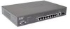
D-Link DES-3010PA User Guide Viewing the Device The D-Link DES-3010PA Fast Ethernet Switch is an 10 port managed switch. The device contains 8 network ports on the front panel for network connectivity, a fiber Gigabit port and a Gigabit Small Form-factor Pluggable (SFP) port to provide an uplink to - D-Link DES-3010PA | Product Manual - Page 12
Back Panel The following figure illustrates the D-Link DES-3010 PA back panel. Figure 2: D-Link DES-3010PA Back Panel Device Description Ports Description The D-Link DES-3010PA back panel is configured as follows. • RPS Connector - Redundant Power Supply (RPS) DC interface. • Power Connector - D-Link DES-3010PA | Product Manual - Page 13
D-Link DES-3010PA User Guide Figure 3: Inserting a GBIC into the Device DB-9 Console Port The DB-9 port is an asynchronous serial console port supporting the RS-232 electrical specification. The port is used to connect the device to a console managing the device. This interface configuration is as - D-Link DES-3010PA | Product Manual - Page 14
following table contains the various cable specification for the DES-3010PA: Table 1: DES-3010PA Cable Specifications Cable Type 10Base-TX 100Base-TX for 1000BASE-ZX Single-mode fiber module (80km) : Table 2: DES-3010PA Cable Lengths Cable Type Fiber 1000Base-T 100Base-TX 10Base-TX Description - D-Link DES-3010PA | Product Manual - Page 15
D-Link DES-3010PA User Guide LED Definitions The device front panels contain Light Emitting Diodes (LED) that indicate the device status. The different LED types are as follows: • Port LEDs - Indicate each port status. • System LEDs - Indicating the device power supply status. Port LEDs 10/100Base- - D-Link DES-3010PA | Product Manual - Page 16
Off Green Off Description A link is established on the port. There is data transmission on the port. No link is established on the port. A 100 Mbps link is established on the port. A 1000 Mbps or 10 Mbps link is established on the port. A 1000 Mbps link is established on the port. A 100 Mbps or 10 - D-Link DES-3010PA | Product Manual - Page 17
D-Link DES-3010PA User Guide SFP Port LEDs The following figure illustrates the SFP port LED. Figure 6: SFP Port LED The SFP ports has one LEDs for Link / Activity. The LED indications are described in the following table: Table 5: SFP Port LED Indications Port Description Link/Activity LED LED - D-Link DES-3010PA | Product Manual - Page 18
the front panel. For each station, the appropriate mode (Half/Full Duplex, Auto Negotiation) is set. The default is Auto Negotiation. Pin Connections for the 10/100/1000 Ethernet Interface The switching port can connect to stations wired in standard RJ-45 Ethernet station mode using straight cables - D-Link DES-3010PA | Product Manual - Page 19
D-Link DES-3010PA User Guide Table 7: RJ-45 Pin Connections for 10/100/1000 Base-T Pin Use 4 TxRx 2- 5 TxRx 3+ 6 TxRx 3- 7 TxRx 4+ 8 TxRx 4- Physical Dimensions The device has the following physical - D-Link DES-3010PA | Product Manual - Page 20
Mounting Device Section 2. Mounting Device This section contains information for installing the device, and includes the following sections: • Preparing for Installation • Installing the Device • Connecting the Device • Rack Installation • Wall Installation Page 19 - D-Link DES-3010PA | Product Manual - Page 21
DLINK DES-3010PA User Guide Preparing for Installation This section provides an explanation for preparing the installation site, and includes the following topics: • Installation Precautions • Site Requirements • Unpacking Installation Precautions Warnings • The surface on which the switch is placed - D-Link DES-3010PA | Product Manual - Page 22
all packing material. 6. Inspect the product for damage. Report any damage immediately. If any item is found missing or damaged, please contact your local D-Link reseller for a replacement. Rack Installation The device can be mounted in an EIA standard-sized, 19-inch rack, which can be placed in - D-Link DES-3010PA | Product Manual - Page 23
DLINK DES-3010PA User Guide Installing the Device The device can be installed on a flat surface or mounted in a rack. This section includes the following topics: • Desktop or Shelf Installation • Rack Installation Desktop or Shelf Installation When installing the switch on a desktop or shelf, the - D-Link DES-3010PA | Product Manual - Page 24
Mounting Device Installing the Device Notes • Disconnect all cables from the unit before mounting the device in a rack or cabinet. • When mounting multiple devices into a rack, mount the devices from the bottom up. To install the device in a rack, perform the following: 1. Place the supplied rack- - D-Link DES-3010PA | Product Manual - Page 25
DLINK DES-3010PA User Guide Figure 11: Mounting Device in a Rack 5. Secure the unit to the rack with the rack screws (not provided). Fasten the lower pair of screws before - D-Link DES-3010PA | Product Manual - Page 26
Mounting Device Installing the Device Wall Installation The device can also be mounted on a wall inside a wiring closet. To mount the device on a wall, perform the following: 1. Mark two holes 100mm apart on the wall. 2. Drill holes into the wall where the marks have been made. The hole diameter and - D-Link DES-3010PA | Product Manual - Page 27
DLINK DES-3010PA User Guide Figure 13: Mounting the device on the wall Connecting the Device This section describes how to connect the device, and includes the following sections: • Connecting the Switch to a Terminal • AC Power Connection Connecting the Switch the appropriate port to connect to - D-Link DES-3010PA | Product Manual - Page 28
2, the arrow keys function properly in HyperTerminal's VT100 emulation. Go to www.microsoft.com for information on Windows 2000 service packs. 3. Connect the cable to the console port on the device front panel. AC Power Connection To connect the power supply perform the following: 1. Using a 5-foot - D-Link DES-3010PA | Product Manual - Page 29
D-Link DES-3010PA User Guide Section 3. Starting and Configuring the Device This section describes initial device configuration and includes the following topics: • Configuring the Terminal • Installation Procedure • Booting the Device • - D-Link DES-3010PA | Product Manual - Page 30
follows: 1. Connect the Chassis serial port to the switch module. The baud rate automatically boots on Windows 2000 service packs. Installation Port Default Settings The following table describes the device port default settings. Table 8: Port Default Setting Function Port speed and mode Port - D-Link DES-3010PA | Product Manual - Page 31
Link DES-3010PA User Guide Booting the Device The assumed bootup information is as follows: • The device is delivered with a default configuration. • The default user name is admin • The default POST (see the last lines) indicates that no problems were encountered during boot. During boot, the - D-Link DES-3010PA | Product Manual - Page 32
be managed either from the already connected Serial port or remotely through an interface defined during the initial configuration. During the initial configuration, you can: • Configure a user name, a password, and the highest privilege level of 15. • Configure the static IP address and the default - D-Link DES-3010PA | Product Manual - Page 33
D-Link DES-3010PA User Guide • The default gateway IP address. • The SNMP community. Static IP Address and Subnet Mask IP interfaces can be configured on each port of the device. After entering the configuration command, it is recommended to check if a port was configured with the IP address by - D-Link DES-3010PA | Product Manual - Page 34
default gateway were properly assigned, execute the following command and examine its output: console # - ip interface Gateway IP Address Activity status 192.168.1.1 Active IP address 192.168.1.123/24 Interface ----------VLAN 1 Type -----Static User Name A user name is used to manage - D-Link DES-3010PA | Product Manual - Page 35
Link DES-3010PA User Guide Note The device is delivered with no community strings configured. The community-string, community-access, and IP address string allows authorized management stations to retrieve MIB objects, while the private string allows authorized management stations to retrieve and - D-Link DES-3010PA | Product Manual - Page 36
Starting and Configuring the Device Configuration Overview Contact: System Location: This completes the initial configuration of the device from a local terminal. The configured parameters enable further device configuration from any remote location. Page 35 - D-Link DES-3010PA | Product Manual - Page 37
D-Link DES-3010PA User Guide Advanced Configuration This section provides information about dynamic allocation of IP addresses and security management based on the authentication, authorization, and accounting (AAA) mechanism, and includes the following topics: • Receiving an IP Address from a DHCP - D-Link DES-3010PA | Product Manual - Page 38
. The device is now configured with an IP address. Security Management and Password Configuration System security is handled through the AAA (Authentication, Authorization, and Accounting) mechanism that manages user access rights, privileges, and management methods. AAA uses both local and remote - D-Link DES-3010PA | Product Manual - Page 39
D-Link DES-3010PA User Guide can be assigned privilege level 15 without a password, it is recommended to always assign a password. If there is no specified password, privileged users can access the web interface with any password. Page 38 - D-Link DES-3010PA | Product Manual - Page 40
commands: console(config)# aaa authentication login default line console(config)# aaa authentication enable default line console(config)# line console console(config-line)# login authentication default console(config-line)# enable authentication default console(config-line)# password george When - D-Link DES-3010PA | Product Manual - Page 41
D-Link DES-3010PA User Guide console(config)# ip http authentication local console(config)# username admin password user1 level 15 Configuring an initial HTTPS Password To configure an initial HTTPS password, enter the following commands: console(config)# ip https authentication local console(config - D-Link DES-3010PA | Product Manual - Page 42
technical support personnel only and are not disclosed in this document. The Startup menu can be entered when booting the device. A user input Test PASS BOOT Software Version 1.0.0.03 Built 09-Mar-2006 19:33:13 DLink 3010 Switch based on 88E6218 with ARM946E-S. 32MByte SDRAM. I-Cache 8 KB. D-Cache - D-Link DES-3010PA | Product Manual - Page 43
D-Link DES-3010PA User Guide Note When selecting an option from the Startup menu, time must be taken into account. If no selection is made within 35 seconds (default), the device times out. This default value can be changed through the CLI. Only technical support personnel can use Diagnostics Mode. - D-Link DES-3010PA | Product Manual - Page 44
management methods. Software Download through TFTP Server This section contains instructions the reserved memory so that it is possible to switch between images if required. On the next boot, TFTP server: 1. Ensure that an IP address is configured on one of the device ports and pings can be sent to - D-Link DES-3010PA | Product Manual - Page 45
Link DES-3010PA User Guide user has no control over the boot image copies. To download a boot image through the TFTP server: 1. Ensure that an IP address is configured on one of the device ports Download through XModem This section contains instructions for downloading device software (system and - D-Link DES-3010PA | Product Manual - Page 46
is not specified within 20 seconds, the command times out. To download a software image file using XModem: 1. Enter the command console# xmodem:image. The switch is ready to receive the file via the XModem protocol. 2. Specify the path of the source file to begin the transfer process. The following - D-Link DES-3010PA | Product Manual - Page 47
D-Link DES-3010PA User Guide D-Link DES-3010PA EWS User Guide Page 46 - D-Link DES-3010PA | Product Manual - Page 48
network management system. The D-Link Embedded Web Interface configures, monitors, and troubleshoots network devices from a remote web browser. The D-Link Embedded Web user interface, and includes the following topics: • Starting the D-Link Embedded Web Interface • Understanding the D-Link Embedded - D-Link DES-3010PA | Product Manual - Page 49
D-Link DES-3010PA User Guide Starting the D-Link Embedded Web Interface This section contains information on starting the D-Link Embedded Web interface. To access the D-Link user interface: 1. Open an Internet browser. 2. Ensure that pop-up blockers are disabled. If pop-up blockers are enabled, edit - D-Link DES-3010PA | Product Manual - Page 50
Getting Started Starting the D-Link Embedded Web Interface Figure 15: D-Link Embedded Web Interface Home Page Page 49 - D-Link DES-3010PA | Product Manual - Page 51
D-Link DES-3010PA User Guide Understanding the D-Link Embedded Web Interface The D-Link Embedded Web Interface Home Page contains the following views: • Port LED Indicators - Located at the top of the home page, the port LED indicators provide a visual representation of the ports on the D-Link front - D-Link DES-3010PA | Product Manual - Page 52
view all the components under a specific feature. Provides a graphic of the device on which D-Link Web Interface runs. Provide access to Link user interface buttons, including both management buttons and task icons. • Using the D-Link Embedded Web Interface Management Buttons - Provides instructions - D-Link DES-3010PA | Product Manual - Page 53
D-Link DES-3010PA User Guide Table 10: D-Link Web Interface Configuration Buttons Button Button Name Test Query Table 11: Ta b D-Link Web Interface Information Tabs Tab Name Help Logout Description Performs cable tests. Queries the device table. Description Opens the online help. Opens the - D-Link DES-3010PA | Product Manual - Page 54
User-defined information can be added to specific D-Link Web Interface pages, by opening a new Add page. To add information to tables or D-Link Web Interface pages: 1. Open a D-Link . Modifying Configuration Information 1. Open the D-Link Embedded Web Interface page. 2. Select a - D-Link DES-3010PA | Product Manual - Page 55
D-Link DES-3010PA User Guide Figure 19: IP Interface Settings Page 4. Modify the fields as required. 5. Click . The fields are modified, and the information is saved to the device. Deleting Configuration Information 1. Open The D-Link Embedded Web Interface page. 2. Select a table row. 3. - D-Link DES-3010PA | Product Manual - Page 56
configuration from being lost, save all changes from the running configuration file to the startup configuration file before resetting the device. For instructions, see "Copying Files" on page 203. To reset the device: 1. Click System > General > Reset. The Reset page opens. Figure 20: Reset Page - D-Link DES-3010PA | Product Manual - Page 57
D-Link DES-3010PA User Guide Figure 21: Reset Confirmation Message 3. Click . The device is reset, and a prompt for a user name and password is displayed. 4. Enter a user name and password to reconnect to the web interface. Page 56 - D-Link DES-3010PA | Product Manual - Page 58
Logging off from the Device 1. Click . The Logout Page opens. Figure 22: Logout Page Getting Started Logging off from the Device 2. Click . The D-Link Embedded Web Interface Home Page closes. Page 57 - D-Link DES-3010PA | Product Manual - Page 59
DLINK DES-3010PA User Guide Section 5. Managing Device Information The System Information Page contains parameters for configuring general device information, including the system name, location, contact, the system MAC Address, System Object ID, System Up Time, System IP and MAC addresses, and both - D-Link DES-3010PA | Product Manual - Page 60
Managing Device Information • Base MAC Address - Displays the device MAC address. • Hardware Version - Displays the installed device hardware version number. • Software Version - Displays the installed software version number. • Boot Version - Displays the current boot version running - D-Link DES-3010PA | Product Manual - Page 61
DLINK DES-3010PA User Guide Section 6. Managing Power over Ethernet Devices Power over Ethernet (PoE) provides power power from the device power supplies, for example IP phones. Powered Devices are connected to the device via Ethernet ports. This section includes the following topics: • Defining - D-Link DES-3010PA | Product Manual - Page 62
Managing Power over Ethernet Devices Defining PoE System Information Defining PoE - Indicates the percentage of power consumed before an alarm is generated. The field value is 1-99 percent. The default is 95 percent. • Traps - Indicate if PoE device traps are enabled. The possible field values are: - - D-Link DES-3010PA | Product Manual - Page 63
DLINK DES-3010PA User Guide 2. Define the System Usage Threshold field. 3. Check the Traps checkbox. 4. Click . The system PoE parameters are defined, and the device is updated. Page 62 - D-Link DES-3010PA | Product Manual - Page 64
Managing Power Ethernet Interface Page contains the following fields: • Port - Indicates the specific interface for which PoE parameters are defined, and the device interfaces, and to learn their classification. This is the default settings. - Never - Disables the Device Discovery protocol, and stops - D-Link DES-3010PA | Product Manual - Page 65
DLINK DES-3010PA User Guide - Fault - Indicates that the device has detected a fault on the powered device. For example, the powered device memory could not be read. • Priority Level - Determines the port priority if the power supply is low. For example, if the power supply is running at 99% usage, - D-Link DES-3010PA | Product Manual - Page 66
Managing Power over Ethernet Devices Defining PoE Interfaces • Overload Counter - Indicates the total power overload occurrences. • Short Counter - Indicates the total power shortage occurrences. • Denied Counter - - D-Link DES-3010PA | Product Manual - Page 67
Link DES-3010PA User Guide Section 7. Configuring Device Security This section provides access to security pages that contain fields for setting security parameters for ports, device management methods, users, and server security. This section contains the following topics: • Configuring Management - D-Link DES-3010PA | Product Manual - Page 68
Security This section provides information for configuring device management security. This section includes the following topics: • Configuring Authentication Methods • Configuring Passwords Configuring Authentication Methods This section provides information for configuring device authentication - D-Link DES-3010PA | Product Manual - Page 69
D-Link DES-3010PA User Guide Defining Access Profiles Access profiles are profiles and rules for accessing the device. Access to management functions can be limited to user groups. User groups are defined for interfaces according to IP addresses or IP subnets. Access profiles contain management - D-Link DES-3010PA | Product Manual - Page 70
. When the packet is matched to a rule, user groups are either granted permission or denied device management access. The rule number is essential to matching packets the device. The device supports SSH 2.0. - HTTP - Assigns HTTP access to the rule. If selected, users accessing the device using HTTP - D-Link DES-3010PA | Product Manual - Page 71
D-Link DES-3010PA User Guide - SNMP - Assigns SNMP access to the rule. If selected, users accessing the device using SNMP, meeting access profile criteria, are permitted or denied access to the device. • Interface - Defines the interface on which the access - D-Link DES-3010PA | Product Manual - Page 72
users can manage the switch module, and by which methods. Users can also be blocked from accessing the device. Rules are composed of filters including: • Rule Priority • Interface • Management Method • IP Address field values are: - Port - Attaches the rule to the selected port. - LAG - Attaches the - D-Link DES-3010PA | Product Manual - Page 73
D-Link DES-3010PA User Guide • Management Method - Defines the management method for which the rule is defined. Users with this access profile can access the device using the management method selected. The possible field values are: - All - Assigns all management methods to the rule. - Telnet - - D-Link DES-3010PA | Product Manual - Page 74
Figure 30: Add Profile Rule Page Configuring Device Security Configuring Management Security 3. Define the Access Profile Name, Priority, Management Method, Interface, Source IP Address, Network Mask or Prefix Length, and Action fields. 4. Click . The profile rule is added to the access profile, - D-Link DES-3010PA | Product Manual - Page 75
D-Link DES-3010PA User Guide Figure 31: Profile Rule Settings Page 3. Modify the fields. 4. Click . The profile rule is modified, and the device is updated. Page 74 - D-Link DES-3010PA | Product Manual - Page 76
methods are RADIUS and Local, and the RADIUS server is not available, then the user is authenticated locally. To define Authentication profiles: 1. Click System > Management Security > Authentication > Authentication Profiles. The Authentication Profile Page opens. Figure 32: Authentication Profile - D-Link DES-3010PA | Product Manual - Page 77
D-Link DES-3010PA User Guide • Remove - Removes the selected authentication profile(s). The possible field values are: - is updated. To modify an authentication profile: 1. Click System > Management Security > Authentication > Authentication Profiles. The Authentication Profile Page opens. - D-Link DES-3010PA | Product Manual - Page 78
Figure 34: Authentication Profile Settings Page Configuring Device Security Configuring Management Security 3. Select an authentication method from the Optional Methods list. 4. Click . The authentication method is selected, and the device is updated. Page 77 - D-Link DES-3010PA | Product Manual - Page 79
D-Link DES-3010PA User Guide Mapping Authentication Methods After authentication profiles are defined, they can be applied to management access methods. For example, console users can be authenticated by Authentication Profile List 1, while Telnet users are authenticated by Authentication Method - D-Link DES-3010PA | Product Manual - Page 80
Authentication first occurs locally. If authentication cannot be verified locally, the RADIUS server authenticates the management method. If the RADIUS server cannot authenticate the management method, the session is permitted. - RADIUS, Local, None - Authentication first occurs at the RADIUS server - D-Link DES-3010PA | Product Manual - Page 81
D-Link DES-3010PA User Guide Defining RADIUS Settings Remote Authorization Dial-In User Service (RADIUS) servers provide additional security for networks. RADIUS servers provide a centralized authentication method for web access. Default parameters are user-defined, and are applied to newly defined - D-Link DES-3010PA | Product Manual - Page 82
the query, or switching to the next server. The possible field values are 1-30. Three is the default value. • Dead Time - Defines the amount of time (in minutes) that a RADIUS server is bypassed for service requests. The range is 0-2000. The default is 0 minutes. • Source IP Address - Defines the - D-Link DES-3010PA | Product Manual - Page 83
DES-3010PA User Guide Figure 37: Add Radius Server Page 3. Define the Host IP Address, Priority, Authenticated Port, Timeout for Reply, Dead Time, and Usage Type fields. 4. Click . The RADIUS server is added, and the device is updated. To edit RADIUS Server Settings: 1. Click System > Management - D-Link DES-3010PA | Product Manual - Page 84
Figure 38: RADIUS Server Settings Page Configuring Device Security Configuring Management Security 3. Define the Priority, Source IP Address, Key String, Authentication Port, Timeout for Reply, Dead Time, and Usage Type fields. 4. Click . The RADIUS server settings are saved, and the device is - D-Link DES-3010PA | Product Manual - Page 85
D-Link DES-3010PA User Guide Configuring Passwords This section contains information for defining device passwords, and includes the following topics. • Defining Local Users • Defining Line Passwords • Defining Enable Passwords Defining Local Users Network administrators can define users, passwords, - D-Link DES-3010PA | Product Manual - Page 86
Page opens: Figure 40: Add Local User Page Configuring Device Security Configuring Management Security In addition to the fields in the Local User Page, the Add Local User Page contains the following fields: • Password - Defines the local user password. Local user passwords can contain up to 159 - D-Link DES-3010PA | Product Manual - Page 87
D-Link DES-3010PA User Guide Defining Line Passwords Network administrators can define line passwords in the Line Password Page. After the line password is defined, a management method is assigned to the password. The device can be accessed using the following methods: • Console • Telnet • Secure - D-Link DES-3010PA | Product Manual - Page 88
Defining Enable Passwords The Enable Password Page sets a local password for a particular access level. To enable passwords: 1. Click System > Management Security > Passwords > Enable Password. The Enable Password Page opens: Figure 42: Enable Password Page The Enable Password Page contains the - D-Link DES-3010PA | Product Manual - Page 89
D-Link DES-3010PA User Guide Configuring Network Security Network security manages both access control lists and locked ports. This section contains the following topics: • Network Security Overview • Defining Network Authentication Properties • Defining Port Authentication • Configuring Traffic - D-Link DES-3010PA | Product Manual - Page 90
. • Unauthenticated VLANS - Are available to users, even if the ports attached to the VLAN are defined as unauthorized. Defining Network Authentication Properties The Network Authentication Properties Page allows network managers to configure network authentication parameters. In addition, Guest - D-Link DES-3010PA | Product Manual - Page 91
D-Link DES-3010PA User Guide • Authentication Method - Specifies the authentication method used. The possible field values are: - None - No authentication method is used to authenticate the port. - RADIUS - Port authentication is performed via RADIUS server. - RADIUS, None - Port authentication is - D-Link DES-3010PA | Product Manual - Page 92
Configuring Device Security Configuring Network Security Defining Port Authentication The Port Authentication Page allows network managers to configure port-based authentication global parameters. To define the port-based authentication global properties: 1. Click Advanced Setup > Network Security > - D-Link DES-3010PA | Product Manual - Page 93
D-Link DES-3010PA User Guide • Enable Periodic Reauthentication - Permits immediate port reauthentication. The possible field values are: - Enable - Immediate port reauthentication is enabled. This is the default value. - Disable - Immediate port reauthentication is disabled. • Reauthentication - D-Link DES-3010PA | Product Manual - Page 94
Page Configuring Device Security Configuring Network Security 3. Modify the Admin Port Control, Enable Periodic Reauthentication, Quiet Period, Resending EAP, Supplicant Timeout, and Server Timeout fields. 4. Click . The port authentication settings are defined, and the device is updated. Page - D-Link DES-3010PA | Product Manual - Page 95
D-Link DES-3010PA User Guide Configuring Multiple Hosts The Multiple Host Page allows network managers to configure advanced port-based authentication settings for specific ports and VLANs. For more information on advanced port-based authentication, see "Advanced PortBased Authentication" on page 88 - D-Link DES-3010PA | Product Manual - Page 96
disabled. The default is 10 seconds. • Status - Indicates the host status. If there is an asterisk (*), the port is either not linked or is down address is not the supplicant MAC address. 2. Click . The Multiple Host Settings Page opens: Figure 47: Multiple Host Settings Page 3. Modify the Port - D-Link DES-3010PA | Product Manual - Page 97
Link DES-3010PA User Guide Defining Authentication Hosts The Authenticated Host Page contains a list of authenticated users. To define authenticated users User Name - Lists the supplicants that were authenticated, and are permitted on each port. • Port - Displays the port on this port (port is forced- - D-Link DES-3010PA | Product Manual - Page 98
on specific ports. Access to the locked port is limited to users with specific MAC addresses. These addresses are either manually defined on the port, or learned on that port up to the point when it is locked. When a packet is received on a locked port, and the packet D-Link source MAC address is - D-Link DES-3010PA | Product Manual - Page 99
D-Link DES-3010PA User Guide 1. Click Advanced Setup > Network Security > Traffic Control > Port Security. The Port Security Page opens. Figure 49: Port Security Page The Port Security Page contains the following fields: • Interface - The port or LAG name. • Interface Status - Indicates the host - D-Link DES-3010PA | Product Manual - Page 100
packets from an unknown source without learning the MAC address. - Discard - Discards packets from any unlearned source. This is the default value. - Shutdown - Discards packets from any unlearned source and shuts down the port. The port remains shut down until reactivated, or until the device - D-Link DES-3010PA | Product Manual - Page 101
D-Link DES-3010PA User Guide Enabling Storm Control Storm control limits the amount of Multicast and Broadcast frames accepted and forwarded by the device. When Layer 2 frames are forwarded, Broadcast and Multicast frames are flooded to all ports on the relevant VLAN. This occupies bandwidth, and - D-Link DES-3010PA | Product Manual - Page 102
which unknown packets are for- warded. The range is 0-1,000,000. The default value is zero. All values are rounded to the nearest 64Kbps. If the Page opens: Figure 52: Storm Control Settings Page 3. Modify the Port, Enable Broadcast Control, Broadcast Mode, and Broadcast Rate Threshold fields. - D-Link DES-3010PA | Product Manual - Page 103
D-Link DES-3010PA User Guide Section 8. Configuring Ports The Interface Configuration Page contains fields for defining port parameters. To define port parameters: 1. Click Basic Setup > Interface > Interface Configuration. The Interface Configuration Page opens. Figure 53: Interface Configuration - D-Link DES-3010PA | Product Manual - Page 104
The interface supports transmission between the device and its link partner in both directions simultaneously. - Half - The interface supports transmission between ) - Use for hubs and switches. • LAG - Indicates whether the port is part of a Link Aggregation (LAG). The Interface Configuration - D-Link DES-3010PA | Product Manual - Page 105
D-Link DES-3010PA User Guide 2. Click . The Port or LAG Interface Settings Page opens: Note In addition to the fields in the Interface Configuration Page, the Port or LAG Configuration Settings Page includes the field Reactivate Suspended Port or Reactivate Suspended Lag. Select this field to - D-Link DES-3010PA | Product Manual - Page 106
Interface - Displays the port number. • Port Type - Displays the port type. The possible field values are: - Copper - Indicates the port has a copper port connection. - Fiber - Indicates the port has a fiber optic port connection. • Description - Provides a user-defined port description To edit the - D-Link DES-3010PA | Product Manual - Page 107
D-Link DES-3010PA User Guide Figure 56: Interface Properties Page 3. Define the fields. 4. Click . The interface properties are modified, and the device is updated. Page 106 - D-Link DES-3010PA | Product Manual - Page 108
multiplies the bandwidth between the devices, increases port flexibility, and provides link redundancy. The device supports both static LAGs and Link Aggregation Control Protocol (LACP) LAGs. LACP LAGs negotiate aggregating ports' links with other LACP ports located on a different device. If the - D-Link DES-3010PA | Product Manual - Page 109
D-Link DES-3010PA User Guide Aggregating Ports Link Aggregated Groups optimize port usage by linking a group of ports together to form a single aggregated group. Link aggregated groups multiply the bandwidth between the devices, increase port flexibility, and provide link redundancy. The LAG - D-Link DES-3010PA | Product Manual - Page 110
Figure 58: LAG Membership Settings Page Aggregating Ports Aggregating Ports 3. Define the Port and LACP fields. 4. Click . The LAG membership settings are saved, and the device is updated. Page 109 - D-Link DES-3010PA | Product Manual - Page 111
Link DES-3010PA User Guide Configuring LACP Aggregate ports can be linked into link-aggregation port-groups. Each group is comprised of ports with the same speed, set to full-duplex operations. LAG ports can contain different media types if the ports are operating at the same speed. Aggregated links - D-Link DES-3010PA | Product Manual - Page 112
Figure 60: LACP Parameters Settings Page Aggregating Ports Configuring LACP 3. Edit the Port Priority and LACP Timeout fields. 4. Click . The LACP settings are saved, and the device is updated Page 111 - D-Link DES-3010PA | Product Manual - Page 113
Link DES-3010PA User Guide Section 10. Configuring VLANs VLANs are logical subgroups with a Local Area Network (LAN) which combine user be implemented. VLANs have no minimum number of ports, and can be created per unit, per device, Registration Protocol) allows network managers to define network nodes - D-Link DES-3010PA | Product Manual - Page 114
field values are: - Dynamic - The VLAN was dynamically created through GARP. - Static - The VLAN is user-defined. - Default - The VLAN is the default VLAN. • Authentication- Indicates whether unauthorized users can access a Guest VLAN. The possible field values are: - Enable - Enables unauthorized - D-Link DES-3010PA | Product Manual - Page 115
D-Link DES-3010PA User Guide 2. Click . The Add VLAN page opens: Figure 62: Add VLAN Page 3. Define the VLAN ID and VLAN Name fields. 4. Click . The VLAN ID is defined, and the device is updated. Page 114 - D-Link DES-3010PA | Product Manual - Page 116
field values are: - Dynamic - The VLAN was dynamically created through GARP. - Static - The VLAN is user-defined. - Default - The VLAN is the default VLAN. • Port - Indicates the port membership. • LAG - Indicates the LAG membership. • Untagged (Orange) - Indicates the interface is an untagged VLAN - D-Link DES-3010PA | Product Manual - Page 117
D-Link DES-3010PA User Guide • Exclude (Gray) - Excludes the interface from the VLAN. However, the interface can be added to the VLAN through GARP. • Forbidden (Red) - Denies the interface VLAN membership, even if GARP indicates the port is to be added. Defining VLAN Interface Settings The VLAN - D-Link DES-3010PA | Product Manual - Page 118
- Indicates the port is part of a PV Community VLAN. • Dynamic - Assigns a port to a VLAN based on the host source MAC address connected to the port. • PVID specific port is not a member. - Disable - Disables ingress filtering on the device. • Reserve VLAN - Indicates the VLAN selected by the user - D-Link DES-3010PA | Product Manual - Page 119
D-Link DES-3010PA User Guide Defining Private VLANs Private VLANs (PVLAN) increase network security by limiting inter-port communication within a VLAN. Private VLANs limit network traffic at the Layer 2 level. Network administrators define a Primary VLAN. Within the Primary VLAN there are Isolated - D-Link DES-3010PA | Product Manual - Page 120
Private VLAN - Contains a list of user-defined Private VLANs. The Private VLANs are defined in the Add Private VLAN page. • Isolated Ports - Indicates which VLAN to which isolated ports are assigned. • Community Ports - Adds a Community VLAN to which community ports are assigned. • Remove - Removes - D-Link DES-3010PA | Product Manual - Page 121
D-Link DES-3010PA User Guide Configuring GARP This section contains of devices interested in a given network attribute, such as VLAN or multicast address. When configuring GARP, ensure the following: • The leave time must be . • Interface - Displays the port or LAG on which GARP is enabled. Page 120 - D-Link DES-3010PA | Product Manual - Page 122
message sent/received, and cancelled by the Join message received. Leave time must be greater than or equal to three times the join time. The default value is 60 centiseconds. • Leave All Timer - Indicates the amount of time lapse, in centiseconds, that all devices wait before leaving the GARP state - D-Link DES-3010PA | Product Manual - Page 123
Link DES-3010PA User Guide Defining GVRP GARP VLAN Registration Protocol (GVRP) is specifically provided for automatic distribution of VLAN membership information among VLAN-aware bridges. GVRP allows VLAN-aware bridges to automatically learn VLANs to bridge ports divided into port and LAG - D-Link DES-3010PA | Product Manual - Page 124
Configuring VLANs Configuring GARP • Dynamic VLAN Creation - Indicates if Dynamic VLAN creation is enabled on the interface. The possible field values are: - Enable - Enables Dynamic VLAN creation on the interface. - Disable - Disables Dynamic VLAN creation on the interface. • GVRP Registration - - D-Link DES-3010PA | Product Manual - Page 125
D-Link DES-3010PA User Guide Section 11. Configuring IP Information This section provides information for defining device IP addresses, and includes the following topics: • Configuring IP Interfaces • Configuring Domain Name Servers Configuring IP Interfaces This section contains information for - D-Link DES-3010PA | Product Manual - Page 126
are forwarded to the default IP when frames are sent to a remote network. The configured IP address must belong to the same IP address subnet of one of the IP interfaces. To define an IP interface: 1. Click Basic Setup > IP Configuration > IP Addressing > IP Interface. The IP Interface Page opens - D-Link DES-3010PA | Product Manual - Page 127
D-Link DES-3010PA User Guide Figure 73: Add IP Interface Page 3. Define the IP Address, Network Mask or Prefix Length, and Interface fields. 4. Click . The IP configuration fields are saved, and the device is updated. To modify an IP interface: 1. Click Basic Setup > IP Configuration > IP - D-Link DES-3010PA | Product Manual - Page 128
Configuring IP Information Configuring IP Interfaces 3. Modify the IP Address, Network Mask or Prefix Length, and Interface fields. 4. Click . The IP Interface is modified, and the device is updated. Page 127 - D-Link DES-3010PA | Product Manual - Page 129
Link DES-3010PA User Guide Defining Default Gateways Packets are forwarded to the default IP when frames are sent to a remote network via the default gateway. The configured IP address must belong to the same subnet of one of the IP interfaces. To define a default gateway: 1. Click Basic Setup > IP - D-Link DES-3010PA | Product Manual - Page 130
> DHCP. The DHCP Page opens: Figure 76: DHCP Page The DHCP Page contains the following fields: • Interface - Displays the interface D-Link IP address which is connected to the device. • Host Name - Displays the system name. • Remove - Removes DHCP interfaces. The possible field values are - D-Link DES-3010PA | Product Manual - Page 131
D-Link DES-3010PA User Guide Figure 77: Add DHCP IP Interface Page 3. Define the Interface and Host Name fields. 4. Click . The DHCP interface is added, and the device is updated. Page 130 - D-Link DES-3010PA | Product Manual - Page 132
IP addresses into physical addresses, and maps the IP address to a MAC address. ARP allows a host to communicate with other hosts only when the IP address of its neighbors is known. To define ARP information: 1. Click Basic Setup > IP Configuration > IP Addressing The default value is Port - The port - D-Link DES-3010PA | Product Manual - Page 133
D-Link DES-3010PA User Guide • IP Address - Indicates the station IP address, which is associated with the MAC address filled in below. • MAC Address - Displays the station MAC address, which is associated in the ARP table with the IP address. • Status - Displays the ARP table entry type. Possible - D-Link DES-3010PA | Product Manual - Page 134
Domain Name Servers Configuring Domain Name Servers Domain Name System (DNS) converts user-defined domain names into IP addresses. Each time a domain name is assigned, the DNS service translates the name into a numeric IP address. For example, www.ipexample.com is translated into 192.87.56.2. DNS - D-Link DES-3010PA | Product Manual - Page 135
D-Link DES-3010PA User Guide Defining DNS Servers The DNS Server Page contains fields for enabling and activating specific DNS servers. To enable a DNS server: 1. Click Basic Setup > IP Configuration > Domain Name System > DNS Server. The DNS Server Page opens: Figure 80: DNS Server Page The DNS - D-Link DES-3010PA | Product Manual - Page 136
All in DNS Server Table. 2. Select Enable DNS. 3. Define the Default Domain Name and Active Server fields. 4. Click . The DNS server is enabled, and the device is updated. To add a new DNS Server: 1. Click Basic Setup > IP Configuration > Domain Name System > DNS Server. The DNS Server Page - D-Link DES-3010PA | Product Manual - Page 137
D-Link DES-3010PA User Guide Defining DNS Host Mapping The DNS Host Mapping Page provides information for defining default DNS domain names. To define DNS host mapping: 1. Click Basic Setup > IP Configuration > Domain Name System > Host Mapping. The DNS Host Mapping Page opens: Figure 82: DNS Host - D-Link DES-3010PA | Product Manual - Page 138
Figure 83: Add DNS Host Page Configuring IP Information Configuring Domain Name Servers 3. Define the Host Name and IP Address fields. 4. Click . The DNS host is added, and the device is updated. Page 137 - D-Link DES-3010PA | Product Manual - Page 139
D-Link DES-3010PA User Guide Section 12. Defining the Forwarding Database Packets addressed to destinations stored in either the Static or Dynamic databases are immediately forwarded to the port. The Dynamic MAC Address Table can be sorted by interface, VLAN, or MAC Address. MAC addresses are - D-Link DES-3010PA | Product Manual - Page 140
contains the following fields: • MAC Address - Displays the MAC address to which the entry refers. • VLAN ID - Displays the VLAN ID number to which the entry refers. • Interface - Displays the interface to which the entry refers: - Port - The specific port number to which the forwarding database - D-Link DES-3010PA | Product Manual - Page 141
Link DES-3010PA User Guide • Remove - Removes the entry. The possible field values are: - Checked - Removes the selected entry. - Unchecked - Maintains the current static forwarding database. Note To prevent static MAC addresses from being deleted when the device is reset, make sure that the port - D-Link DES-3010PA | Product Manual - Page 142
fields: • Aging Interval (secs)- Specifies the amount of time the MAC address remains in the Dynamic MAC Address table before it is timed out, if no traffic from the source is detected. The default value is 300 seconds. • Port - Specifies the interface for which the table is queried. There are two - D-Link DES-3010PA | Product Manual - Page 143
D-Link DES-3010PA User Guide 2. Define the fields. 3. Click . The Dynamic Address Aging field is defined, and the device is updated. To query the Dynamic MAC Address Table: 1. Click Advanced Setup > Forwarding Database > Dynamic Addresses. The Dynamic Addresses Page opens. 2. Select a port, MAC - D-Link DES-3010PA | Product Manual - Page 144
, resulting in increased traffic and reducing network efficiency. The device supports the following STP versions: • Classic STP - Provides a single Provides various load balancing scenarios. For example, if port A is blocked in one STP instance, the same port can be placed in the Forwarding State in - D-Link DES-3010PA | Product Manual - Page 145
Link DES-3010PA User Guide : - Classic STP - Enables Classic STP on the device. This is the default value. - Rapid STP - Enables Rapid STP on the device. - Multiple BPDU Handling - Determines how BPDU packets are managed when STP is disabled on the port or device. BPDUs are used to transmit spanning - D-Link DES-3010PA | Product Manual - Page 146
listening and learning state before forwarding packets. The default is 10 seconds. • Bridge ID - Identifies the Bridge priority and MAC address. • Root Bridge ID - Identifies the Root Bridge priority and MAC address. • Root Port - Indicates the port number that offers the lowest cost path from this - D-Link DES-3010PA | Product Manual - Page 147
D-Link DES-3010PA User Guide Defining STP on Interfaces Network administrators can assign STP settings to specific interfaces using the STP Interface Page. The Global LAGs section displays the STP information for Link Aggregated Groups. To assign STP settings to an interface: 1. Click Advanced Setup - D-Link DES-3010PA | Product Manual - Page 148
ID - Indicates the bridge priority and the MAC Address of the designated bridge. • Designated Port ID - Indicates the selected port D-Link priority and interface. • Designated Cost - Indicates the cost of the port participating in the STP topology. Ports with a lower cost are less likely to be - D-Link DES-3010PA | Product Manual - Page 149
D-Link DES-3010PA User Guide 4. Define the Fast Link, Enable Root Guard, Path Cost, Default Path Cost, and Priority fields. 5. Click . STP is enabled on the interface, and the device is updated. Page 148 - D-Link DES-3010PA | Product Manual - Page 150
- Provides an alternate path to the root switch from the root interface. - Backup - Provides a backup path to the designated port path toward the Spanning Tree leaves. Backup ports occur only when two ports are connected in a loop by a point-to-point link, or when a LAN has two or more connections - D-Link DES-3010PA | Product Manual - Page 151
D-Link DES-3010PA User Guide • Mode-Displays the current STP mode. The STP mode is selected in sent over the link. The link remains configured for communications until explicit LCP or NCP packets close the link, or until some external event occurs. This is the actual switch port link type. It may - D-Link DES-3010PA | Product Manual - Page 152
Figure 91: RSTP Settings Page Configuring Spanning Tree Defining Rapid Spanning Tree 3. Define the Interface, Point-to-Point Admin Status and Activate Protocol Migration fields. 4. Click . RSTP is defined for the interface, and the device is updated. Page 151 - D-Link DES-3010PA | Product Manual - Page 153
D-Link DES-3010PA User Guide Defining Multiple Spanning Tree Multiple Spanning Tree (MSTP) provides differing load balancing scenarios. For example, while port A is blocked in one STP instance, the same port can be placed in the Forwarding state in another STP instance. The MSTP Properties Page - D-Link DES-3010PA | Product Manual - Page 154
0-61440 • Designated Root Bridge ID - Indicates the ID of the bridge with the lowest path cost to the instance ID. • Root Port - Indicates the selected instance's root port. • Root Path Cost - Indicates the selected instance's path cost. • Bridge ID - Indicates the bridge ID of the selected instance - D-Link DES-3010PA | Product Manual - Page 155
D-Link DES-3010PA User Guide Figure 94: VLAN Instance Configuration Table 3. Define the Instance ID field. 4. Click . The MSTP Instances are assigned, and the device is updated. Page 154 - D-Link DES-3010PA | Product Manual - Page 156
MSTP on the interface. - Disabled - Disables MSTP on the interface. • Port State- Indicates whether the port is enabled for the specific instance. The possible field values are: - Enabled - Enables the port for the specific instance. - Disabled - Disables the port for the specific instance. Page 155 - D-Link DES-3010PA | Product Manual - Page 157
D-Link DES-3010PA User Guide • Type - Indicates whether the port is a Boundary or Master port. The possible field values are: - Boundary Port - Indicates that the port is a Boundary port. A Boundary port attaches MST bridges to LANs in an outlying region. If the port is a Boundary port, this field - D-Link DES-3010PA | Product Manual - Page 158
Figure 96: MSTP Interface Table Configuring Spanning Tree Defining Multiple Spanning Tree 3. Define the Port Priority and the Path Cost fields. 4. Click . The MSTP interface settings are defined, and the device is updated. Page 157 - D-Link DES-3010PA | Product Manual - Page 159
D-Link DES-3010PA User Guide Section 14. Configuring Multicast Forwarding This section contains the following topics: • Defining IGMP Snooping • Defining Multicast Bridging Groups • Defining Multicast Forward All Settings Page 158 - D-Link DES-3010PA | Product Manual - Page 160
and Multicast traffic. Ports requesting to join a specific Multicast group issue an IGMP report, specifying that Multicast group is accepting members. This results in the creation of the Multicast filtering database. To enable IGMP Snooping: 1. Click Multicast Support - D-Link DES-3010PA | Product Manual - Page 161
D-Link DES-3010PA User Guide • Auto Learn - Indicates if Auto Learn is enabled on the device. a Leave Timeout occurs, the switch notifies the Multicast device to stop sending traffic The Leave Timeout value is either user-defined, or an immediate leave value. The default timeout is 10 seconds. 2. - D-Link DES-3010PA | Product Manual - Page 162
groups to be created. The Multicast Group Page also assigns ports to a specific Multicast service address group. To define Multicast groups: 1. Click Advanced Setup > Multicast Support > Bridge Multicast > Multicast Group. The Multicast Group Page opens: Figure 99: Multicast Group Page The Multicast - D-Link DES-3010PA | Product Manual - Page 163
D-Link DES-3010PA User Guide The following table contains the IGMP port and LAG members management settings: Table 12: IGMP Port/LAG Members Table Control Settings Port Control D S F Blank Definition Dynamically joins ports/LAG to the Multicast group in the Current Row. Attaches the port to the - D-Link DES-3010PA | Product Manual - Page 164
a Multicast service. The following table summarizes the Multicast settings which can be assigned to ports in the Multicast Forward All Page. Table 13: Bridge Multicast Forward All Router/Port Control Settings Table Port Control D S Definition Attaches the port to the Multicast router or switch as - D-Link DES-3010PA | Product Manual - Page 165
D-Link DES-3010PA User Guide Table 13: Bridge Multicast Forward All Router/Port Control Settings Table Port Control F Blank Definition Forbidden. The port is not attached to a Multicast router or switch. 2. Select a VLAN in the VLAN ID drop-down box. 3. Define the VLAN port settings. 4. Click - D-Link DES-3010PA | Product Manual - Page 166
are used to manage the device. The variables are defined in the Management Information Base (MIB). The SNMP agent defines the MIB specification format, as well time information. • Key Management - Defines key generation, key updates, and key use. The device supports SNMP notification filters based on - D-Link DES-3010PA | Product Manual - Page 167
D-Link DES-3010PA User Guide Configuring SNMP Security This section contains information for configuring SNMP security parameters, and . The Engine ID must be defined before SNMPv3 is enabled. Select a default Engine ID that is comprised of an Enterprise number and the default MAC address. Page 166 - D-Link DES-3010PA | Product Manual - Page 168
= 1, the rest is IANA Enterprise number. - Fifth octet - Set to 3 to indicate the MAC address that follows. - Last 6 octets - MAC address of the device. 2. Define the Local Engine ID and Use Default fields. 3. Click . The SNMP global security parameters are set, and the device is updated. Page - D-Link DES-3010PA | Product Manual - Page 169
D-Link DES-3010PA User Guide Defining SNMP Views SNMP views provide or block access to device Views Page The SNMP Security Views Page contains the following fields: • View Name - Displays the user-defined views. The view name can contain a maximum of 30 alphanumeric characters. • Object ID Subtree - D-Link DES-3010PA | Product Manual - Page 170
Figure 104:Add SNMP View Page Configuring SNMP Configuring SNMP Security 3. Define the View Name field. 4. Define the view using and . 5. Define the View Type field. 6. Click . The view is defined, and the device is updated. Page 169 - D-Link DES-3010PA | Product Manual - Page 171
D-Link DES-3010PA User Guide Defining SNMP Group Profiles The SNMP Group Profile Page provides information for creating SNMP groups, and assigning SNMP access control privileges to SNMP groups. Groups allow network managers to assign access rights to specific device features, or feature aspects. To - D-Link DES-3010PA | Product Manual - Page 172
, and ensures that the SNMP message's origin is authenticated. - Privacy - Encrypts SNMP messages. • Operation - Defines the group access rights. The possible field values are: - Read - Management access is restricted to read-only, and changes cannot be made to the assigned SNMP view. - Write - D-Link DES-3010PA | Product Manual - Page 173
D-Link DES-3010PA User Guide Figure 107:SNMP Group Profile Settings Page 3. Modify the Group Name, Security Model, Security Level, and Operation fields. 4. Click . The SNMP group profile is modified, and the device is updated. Page 172 - D-Link DES-3010PA | Product Manual - Page 174
Membership. The SNMP Group Membership Page opens: Figure 108:SNMP Group Membership Page The SNMP Group Membership Page contains the following fields: • User Name - Contains a list of user-defined user names. The field range is up to 30 alphanumeric charac- ters. • Group Name - Contains a list of - D-Link DES-3010PA | Product Manual - Page 175
Link DES-3010PA User Guide - No Authentication - No user authentication is used. • Remove - Removes users from a specified group. The possible field values are: - Checked - Removes the selected user(s). - Unchecked - Maintains the user the group member 3. Define the User Name, Group Name, Engine ID, - D-Link DES-3010PA | Product Manual - Page 176
Figure 110: SNMP Group Membership Settings Page Configuring SNMP Configuring SNMP Security 3. Modify the Group Name, Engine ID, Authentication Method, Password, Authentication Key, and Privacy Key fields. 4. Click . The SNMP group membership is modified, and the device is updated. Page 175 - D-Link DES-3010PA | Product Manual - Page 177
D-Link DES-3010PA User Guide Defining SNMP Communities Access rights are managed by defining communities in the SNMP Communities Communities Basic Table contains the following fields: • Management Station - Displays the management station IP address for which the basic SNMP community is defined. - D-Link DES-3010PA | Product Manual - Page 178
as permissions to modify the community. • View Name - Contains a list of user-defined SNMP views. • Remove - Removes a community. The possible field values are Tables contains the following fields: • Management Station - Displays the management station IP address for which the advanced SNMP community - D-Link DES-3010PA | Product Manual - Page 179
D-Link DES-3010PA User Guide Figure 113: SNMP Community Settings Page 3. Modify the SNMP Management Station, Community String, and Basic or Advanced fields. 4. Click . The SNMP community is modified, and the device is updated. Page 178 - D-Link DES-3010PA | Product Manual - Page 180
Configuring SNMP Configuring SNMP Notifications Configuring SNMP Notifications This section contains information for configuring SNMP Notifications, and contains the following topics: • Defining SNMP Notification Global Parameters • Defining SNMP Notification Filters • Defining SNMP Notification - D-Link DES-3010PA | Product Manual - Page 181
D-Link DES-3010PA User Guide Defining SNMP Notification Global Parameters The SNMP Notification Properties Page contains parameters for defining SNMP notification parameters. To define SNMP notification global parameters: 1. Click System > - D-Link DES-3010PA | Product Manual - Page 182
OID is linked to a device feature or a portion of a feature. The SNMP Notification Filter Page also allows network managers to filter Page contains the following fields: • Filter Name - Contains a list of user-defined notification filters. • Object ID Subtree - Displays the OID for which - D-Link DES-3010PA | Product Manual - Page 183
D-Link DES-3010PA User Guide Figure 116: Add SNMP Notification Filter Page 3. Define the Filter Name, New Object Identifier Tree, and Filter Type fields. 4. Click . The SNMP notification filter is defined, and the device is updated. Page 182 - D-Link DES-3010PA | Product Manual - Page 184
information for defining filters that determine whether traps are sent to specific users, and the trap type sent. SNMP notification filters provide the following services: • Identifying Management Trap Targets • Trap Filtering • Selecting Trap Generation Parameters • Providing Access Control - D-Link DES-3010PA | Product Manual - Page 185
D-Link DES-3010PA User Guide SNMPv1,2c Notification Recipient The SNMPv1,2 cNotification Recipient table contains the following fields: • Recipients IP - Displays the IP address to which the traps are sent. • Notification Type - Displays the notification sent. The possible field values are: - Trap - - D-Link DES-3010PA | Product Manual - Page 186
- Displays the IP address to which the traps are sent. • Notification Type - Displays the type of notification sent. The possible field values are: - Trap - Indicates that traps are sent. - Inform - Indicates that informs are sent. • User Name - Displays the user to which SNMP notifications are sent - D-Link DES-3010PA | Product Manual - Page 187
D-Link DES-3010PA User Guide 3. Define the Recipient IP, Notification Type, SNMPV1,v2c or SNMPv3, UPD Port, Filter Name, TImeout, and Retries fields. 4. Click Page 3. Modify the Notification Type, SNMPV1,v2c or SNMPv3, UPD Port, Filter Name, TImeout, and Retries fields. 4. Click . The SNMP - D-Link DES-3010PA | Product Manual - Page 188
Quality of Service Quality of Service (QoS) specific values. All packets matching the userdefined specifications are classified together. • Action - Defines traffic management assignments are user-definable. Packets arriving untagged are assigned a default VPT value, which is set on a per-port basis. - D-Link DES-3010PA | Product Manual - Page 189
Link DES-3010PA User Guide CoS Services After packets are assigned to a specific egress queue, Class of Service (CoS) services , under SP, voice over IP (VoIP) traffic can be serviced before WRR queues. If the traffic flow is minimal, and SP queues do not occupy the whole bandwidth allocated to a port - D-Link DES-3010PA | Product Manual - Page 190
on predefined fields within the packet to determine the egress queue settings. To define the QoS settings: 1. Click Basic Setup > Quality of Service > General Settings > General Settings. The QoS General Settings Page opens. Figure 120:QoS General Settings Page The QoS General Settings Page displays - D-Link DES-3010PA | Product Manual - Page 191
D-Link DES-3010PA User Guide • Trust Mode - Defines which packet fields to use for classifying packets entering the device. When value. - DSCP - Classifies traffic based on the DSCP tag value. 2. Select Enable in the Quality of Service field. 3. Define the Trust Mode field. 4. Click . Quality of - D-Link DES-3010PA | Product Manual - Page 192
interface. Modifying queue scheduling affects the queue settings globally. To define the bandwidth settings: 1. Click Basic Setup > Quality of Service > General Settings > Bandwidth Settings. The Bandwidth Settings Page opens. Figure 121:Bandwidth Settings Page The Bandwidth Settings Page displays - D-Link DES-3010PA | Product Manual - Page 193
D-Link DES-3010PA User Guide Modifying QoS Interface Settings The QoS Interface Page allows network managers to modify the QoS settings assigned to a specific interface. To set the QoS interface settings: 1. Click System > QoS > General Settings > Interface Settings. The QoS Interface Page opens. - D-Link DES-3010PA | Product Manual - Page 194
Figure 123:Edit Interface Settings Page Configuring Quality of Service Defining Bandwidth Settings 3. Define the Disable Trust Mode, Default CoS, and Restore Defaults fields. 4. Click . The QoS Interface settings are modified, and the device is updated. Page 193 - D-Link DES-3010PA | Product Manual - Page 195
D-Link DES-3010PA User Guide Defining Queue Settings The Queue Page contains fields for defining the QoS queue forwarding types. To set the queue settings: 1. Click Basic Setup > Quality of Service > General Settings > Queue. The Queue Page opens. Figure 124:Queue Page The Queue Page contains the - D-Link DES-3010PA | Product Manual - Page 196
Page The CoS to Queue Page contains the following fields: • Class of Service - Specifies the CoS priority tag values, where zero is the lowest and mapped. Four traffic priority queues are supported. • Restore Defaults - Restores the device factory defaults for mapping CoS values to a forwarding - D-Link DES-3010PA | Product Manual - Page 197
Link DES-3010PA User Guide Mapping DSCP Values to Queues The DSCP to Queue Page contains fields for mapping DSCP settings to traffic queues. For example, a packet with a DSCP tag value of 3 can be assigned to queue 2. To map CoS values to queues: 1. Click Basic Setup > Quality of Service supported. - D-Link DES-3010PA | Product Manual - Page 198
Managing System Files Section 17. Managing System Files File maintenance includes both configuration file management as well as device access. This section contains the following topics: • File Management Overview • Downloading System Files • Uploading System Files • Copying Files Page 197 - D-Link DES-3010PA | Product Manual - Page 199
D-Link DES-3010PA User Guide File Management Overview The configuration file structure consists of the following configuration files: • Startup Configuration File - Contains the commands required to reconfigure the device to the same - D-Link DES-3010PA | Product Manual - Page 200
of files, firmware files and configuration files. The firmware files manage the device, Firmware Download - Indicates that the download is for firmware. If Firmware Download is selected, the Configuration Download fields are grayed out. • TFTP Server IP Address - Specifies the TFTP Server IP Address - D-Link DES-3010PA | Product Manual - Page 201
D-Link DES-3010PA User Guide - Boot Code - Downloads the Boot file. • Download to Master Only - Downloads If Configuration Download is selected, the Firmware Download fields are grayed out. • TFTP Server IP Address - Specifies the TFTP Server IP Address from which the configuration files are - D-Link DES-3010PA | Product Manual - Page 202
to the TFTP server. To upload a system file: 1. Click System > File Management > File Upload. The File Upload page opens: Figure 128:File Upload Page The the following fields: • Firmware Upload - Specifies that the software image file is uploaded. If Firmware Upload is selected, the Configuration - D-Link DES-3010PA | Product Manual - Page 203
D-Link DES-3010PA User Guide Software Image Upload The Software Image Upload section contains the following fields: • TFTP Server IP Address - Specifies the TFTP Server IP Address to which the Software Image is uploaded. • Destination File Name - Specifies the software image file path to which the - D-Link DES-3010PA | Product Manual - Page 204
Configuration. 3. Click . The file is copied. Restoring the Default Configuration File 1. Click System > File Management > Copy Files. The Copy Files Page opens. 2. Select Restore Configuration Factory Defaults. 3. Click . The factory defaults are restored, and the device is updated. Page 203 - D-Link DES-3010PA | Product Manual - Page 205
Link DES-3010PA User Guide Section 18. Managing System Logs This section provides information for managing system logs. The system logs enable viewing device events in real time, and recording the events for later usage. System Logs record and manage contact Customer Tech Support. This section - D-Link DES-3010PA | Product Manual - Page 206
Managing , File, and Server Logs are enabled. Console logs are enabled by default. The possible field values are: - Checked - Enables device logs. ports are not functioning, while the rest of the device ports remain functional. - Error - A device error has occurred, for example, if a single port - D-Link DES-3010PA | Product Manual - Page 207
D-Link DES-3010PA User Guide - Notice - Provides device information. - Informational - Provides device information. - Debug - Provides debugging messages. Note When a severity level is selected, all severity level choices above the selection - D-Link DES-3010PA | Product Manual - Page 208
Managing System Logs Viewing the Device Memory Logs Viewing the Device Memory Logs The Device Memory Log Page contains all system logs in a chronological order that - D-Link DES-3010PA | Product Manual - Page 209
D-Link DES-3010PA User Guide Viewing the FLASH Logs The Syslog Flash Page contains information about log entries saved to the log file in Flash, including the time the log - D-Link DES-3010PA | Product Manual - Page 210
Managing can be sent. • UDP Port - Defines the UDP port to which the server logs are sent. The possible range is 1 - 65535. The default value is 514. • Facility . The field default is Local 7. The possible field values are Local 0 - Local 7. • Description - Provides a user-defined server description - D-Link DES-3010PA | Product Manual - Page 211
D-Link DES-3010PA User Guide Section 19. Managing Device Diagnostics This section contains the following topics: • Configuring Port Mirroring • Viewing Integrated Cable Tests • Viewing Optical Transceivers • Viewing the CPU Utilization Page 210 - D-Link DES-3010PA | Product Manual - Page 212
and outgoing packets from one port to a monitoring port. Port mirroring can be used as a diagnostic tool as well as a debugging feature. Port mirroring also enables switch performance monitoring. Network administrators can configure port mirroring by selecting a specific port from which to copy all - D-Link DES-3010PA | Product Manual - Page 213
D-Link DES-3010PA User Guide - Active - Indicates the port is currently monitored. - Ready - Indicates the port is not currently monitored. • Remove - Removes the port mirroring session. The possible field values are: - Checked - Removes the selected port mirroring sessions. - Unchecked - Maintains - D-Link DES-3010PA | Product Manual - Page 214
Managing Device Diagnostics Viewing Integrated Cable Tests Viewing Integrated Displays the cable test results. Possible values are: - No Cable - Indicates that a cable is not connected to the port. - Open Cable - Indicates that a cable is connected on only one side. - Short Cable - Indicates that a - D-Link DES-3010PA | Product Manual - Page 215
D-Link DES-3010PA User Guide Viewing Optical Transceivers The Optical Transceiver page allows network managers to perform tests on Fiber Optic cables. Optical transceiver diagnostics can be performed only when the link is present. To test cables: • Click Advanced Setup > Diagnostics > Optical - D-Link DES-3010PA | Product Manual - Page 216
Managing Device Diagnostics Viewing the CPU Utilization Viewing the CPU Utilization The CPU Utilization Page contains information about the system's CPU utilization. To view the CPU - D-Link DES-3010PA | Product Manual - Page 217
D-Link DES-3010PA User Guide Section 20. Configuring System Time This section provides information for configuring system time parameters, including: • Configuring Daylight Savings Time • Configuring SNTP Page 216 - D-Link DES-3010PA | Product Manual - Page 218
local hardware clock. Daylight Savings Time can be enabled on the device. The following is a list of Daylight Savings Time start and end times in specific countries: • Albania - From the last weekend of March until the last weekend of October. • Australia - From the end of October until the end of - D-Link DES-3010PA | Product Manual - Page 219
D-Link DES-3010PA User Guide • Mexico - From the first Sunday in April at 02:00 to the last Sunday in October at 02:00. • Moldova - From the last weekend of - D-Link DES-3010PA | Product Manual - Page 220
specific date in a particular year or a recurring setting irrespective of the year. For a specific setting in a particular year complete the Daylight Savings area, and for a recurring setting, complete the Recurring area. The possible field values are: - USA - Enables switching switching user - D-Link DES-3010PA | Product Manual - Page 221
D-Link DES-3010PA User Guide • From - Indicates the time that DST begins in countries 30. 2. Define the Date, Local Time and Time Zone Offset fields. 3. To configure the device to automatically switch to DST, select Daylight Savings and select either USA, Euro- pean, or Other. If you select Other, - D-Link DES-3010PA | Product Manual - Page 222
supports the Simple Network Time Protocol (SNTP). SNTP assures accurate network device clock time synchronization up to the millisecond. Time synchronization is performed by a network SNTP server. The device operates only as an SNTP client, and cannot provide time services linked to IP address - D-Link DES-3010PA | Product Manual - Page 223
D-Link DES-3010PA User Guide This section contains the following topics: • Defining SNTP Global Settings • Defining SNTP Authentication • Defining SNTP Servers • Defining SNTP Interface Settings Page 222 - D-Link DES-3010PA | Product Manual - Page 224
following fields: • Poll Interval - Defines the interval (in seconds) at which the SNTP server is polled for Unicast information. The Poll Interval default is 1024 seconds. • Enable Receive Broadcast Servers Updates - Defines whether or not the device monitors the SNTP serv- ers for Broadcast server - D-Link DES-3010PA | Product Manual - Page 225
D-Link DES-3010PA User Guide Servers Updates, and Enable Receive Unicast Servers Updates fields are all enabled, the system time is set according to the Unicast server time information. The - D-Link DES-3010PA | Product Manual - Page 226
possible field values are: - Checked - Removes the selected Encryption Key ID(s). - Unchecked - Maintains the Encryption Key ID(s). This is the default value. 2. To enable SNTP Authentication, select Enable SNTP Authentication and click tion is defined, and the device is updated. . SNTP Authentica - D-Link DES-3010PA | Product Manual - Page 227
D-Link DES-3010PA User Guide To define SNTP authentication parameters: 1. Click . The Add SNTP Authentication page opens: Figure 143: Add SNTP Authentication 2. Define the Encryption Key ID, Authentication Key, and - D-Link DES-3010PA | Product Manual - Page 228
Servers Page The SNTP Servers Page contains the following fields: • SNTP Server - Displays user-defined SNTP server IP addresses. Up to eight SNTP servers can be defined. • Poll Interval - Indicates whether the SNTP server. - Unchecked - Maintains the SNTP server. This is the default value. Page 227 - D-Link DES-3010PA | Product Manual - Page 229
D-Link DES-3010PA User Guide 2. Click . The Add SNTP Server Page opens: Figure 145:Add SNTP Server Page 3. Define the SNTP Server, Enable Poll Interval, and Encryption Key ID fields. 4. Click . The SNTP Server is added, and the device is updated. Page 228 - D-Link DES-3010PA | Product Manual - Page 230
on which SNTP can be enabled. The possible field values are: - Port - Indicates the specific port number on which SNTP is enabled. - LAG - Indicates the specific LAG number on which SNTP is enabled. - VLAN - Indicates the specific VLAN number on which SNTP is enabled. • Receive Servers Updates - D-Link DES-3010PA | Product Manual - Page 231
D-Link DES-3010PA User Guide Figure 147: Add SNTP Interface Page 3. Define the Interface and Receive Server Updates fields. 4. Click . The SNTP interface is added, and the device is updated. Page 230 - D-Link DES-3010PA | Product Manual - Page 232
+ authentication settings: 1. Click System > Management Security > Authentication > TACACS+. The TACACS+ Page opens. Figure 148: TACACS+ Page The Default Parameters section contains the following fields: • Source IP Address - Defines the default device source IP address used for the TACACS+ session - D-Link DES-3010PA | Product Manual - Page 233
D-Link DES-3010PA User Guide • Key String - Defines the default authentication and encryption key for TACACS+ communication between the device and the TACACS+ server. • Timeout for Reply - Defines the default time that passes before the connection between the device and the TACACS+ times out. The - D-Link DES-3010PA | Product Manual - Page 234
3. Define the Host IP Address, Priority, Source IP Address, Key String, Authentication Port, Timeout for Reply, and Single Connection. 4. Click . The TACACS+ server is defined, and the device is updated. To edit a TACACS+ server settings: 1. Click System > Management Security >Authentication - D-Link DES-3010PA | Product Manual - Page 235
D-Link DES-3010PA User Guide Section 22. Viewing Statistics This section provides device statistics for RMON, interfaces, GVRP, EAP, and Etherlike statistics. This section contains the following topics: • Viewing Interface Statistics • Managing RMON Statistics Viewing Interface Statistics This - D-Link DES-3010PA | Product Manual - Page 236
- Indicates the device for which statistics are displayed. The possible field values are: - Port - Defines the specific port for which interface statistics are displayed. - LAG - Defines the specific LAG for which interface statistics are displayed. • Refresh Rate - Defines the amount of time - D-Link DES-3010PA | Product Manual - Page 237
D-Link DES-3010PA User Guide Transmit Statistics • Total Bytes (Octets) - Displays the number of octets transmitted from the selected interface. • Unicast Packets - Displays the number of Unicast packets transmitted from - D-Link DES-3010PA | Product Manual - Page 238
- Indicates the device for which statistics are displayed. The possible field values are: - Port - Defines the specific port for which Etherlike statistics are displayed. - LAG - Defines the specific LAG for which Etherlike statistics are displayed. • Refresh Rate - Defines the amount of time - D-Link DES-3010PA | Product Manual - Page 239
D-Link DES-3010PA User Guide Viewing GVRP Statistics The GVRP Statistics Page contains device statistics for GVRP • Interface-Specifies the interface type for which the statistics are displayed. - Port-Indicates port statistics are displayed. - LAG-Indicates LAG statistics are displayed. • Refresh - D-Link DES-3010PA | Product Manual - Page 240
. The GVRP statistics counters are cleared. Viewing EAP Statistics The EAP Statistics Page contains information about EAP packets received on a specific port. To view the EAP Statistics: • Click Advanced Setup > Interface Statistics > EAP. The EAP Statistics Page opens. Figure 154:EAP Statistics - D-Link DES-3010PA | Product Manual - Page 241
D-Link DES-3010PA User Guide The EAP Statistics Page contains the following fields: • Port-Indicates the port, which is polled port. • Last Frame Version - Indicates the protocol version number attached to the most recently received EAPOL frame. • Last Frame Source - Indicates the source MAC address - D-Link DES-3010PA | Product Manual - Page 242
Viewing Statistics Managing RMON Statistics Managing RMON Statistics This section contains the following topics: • . The possible field values are: - Port - Defines the specific port for which RMON statistics are displayed. - LAG - Defines the specific LAG for which RMON statistics are displayed. - D-Link DES-3010PA | Product Manual - Page 243
D-Link DES-3010PA User Guide - 60 Sec - Indicates that the RMON statistics are refreshed every 60 seconds. • Drop Events - Displays the number of dropped events that have occurred on the - D-Link DES-3010PA | Product Manual - Page 244
seconds the time that samplings are taken from the ports. The field range is 1-3600. The default is 1800 seconds (equal to 30 minutes). • Samples The default value is 50. • Current No. of Samples in List - Displays the current number of samples taken. • Owner - Displays the RMON station or user that - D-Link DES-3010PA | Product Manual - Page 245
D-Link DES-3010PA User Guide • Remove - Removes History Control entries. The possible field values are: - Checked - Removes the selected History Control entry. - Unchecked - Maintains the current History Control entries. 2. Click . - D-Link DES-3010PA | Product Manual - Page 246
Viewing Statistics Managing RMON Statistics Viewing the RMON History Table The RMON History Table Page contains interface specific statistical network the History Control Table page. • Owner - Displays the RMON station or user that requested the RMON information. The field range is 0-20 characters. • - D-Link DES-3010PA | Product Manual - Page 247
D-Link DES-3010PA User Guide • Oversize Packets - Displays the number of oversized packets (over 1518 octets) received on the interface since the device was last refreshed. • Fragments - Displays the number - D-Link DES-3010PA | Product Manual - Page 248
Viewing Statistics Managing RMON Statistics Configuring RMON Events This section includes the event occurred. • Time - Displays the time that the event occurred. • Owner - Displays the device or user that defined the event. • Remove - Removes a RMON event. The possible field values are: - Checked - - D-Link DES-3010PA | Product Manual - Page 249
D-Link DES-3010PA User Guide Viewing the RMON Events Logs The RMON Events Logs Page contains a list of RMON events. To view RMON event logs: • Click Advanced Setup > RMON > Events > - D-Link DES-3010PA | Product Manual - Page 250
Alarm Page contains the following fields: • Alarm Entry - Indicates a specific alarm. • Counter Name - Displays the selected MIB variable. • Interface - Displays interface for which RMON statistics are displayed. The possible field values are: - Port - Displays the RMON statistics for the selected - D-Link DES-3010PA | Product Manual - Page 251
D-Link DES-3010PA User Guide • Startup Alarm - Displays the trigger that activates the alarm generation. Rising is defined by crossing the threshold from a low-value threshold to a higher-value threshold. • Interval - Defines the alarm interval time in seconds. • Owner - Displays the device or user - D-Link DES-3010PA | Product Manual - Page 252
topics: • Hardware Specifications • DES-3010PA Features Hardware Specifications This section contains the DES-3010PA hardware specifications: Ports provides 24-Port 10/100Mbps + 2 Combo Copper/SFP (100BASE-FX/1000BASE-X Fiber ports) + 2 1000 Mbps Copper L2 Management Switch CPU DDRAM 64MB Max - D-Link DES-3010PA | Product Manual - Page 253
Link DES-3010PA User Guide DES-3010PA Features This appendix describes the device features. The system supports the following features: Feature Auto Negotiation Automatic MAC Addresses Aging Back Pressure Class Of Service Command Line Interface Configuration File Management and port specific device - D-Link DES-3010PA | Product Manual - Page 254
Appendix A, Device Specifications & Features Feature Domain Name System Fast Link Full 802.1Q VLAN Tagging Compliance GVRP Support IGMP Snooping LACP Link Aggregated Groups MAC Address Capacity Support Description Domain Name System (DNS) converts user-defined domain names into IP addresses. Each - D-Link DES-3010PA | Product Manual - Page 255
D-Link DES-3010PA User Guide Feature MAC Multicast Support MDI/MDIX Support Multiple Spanning Tree Password Management Port Based Authentication Port Based Virtual LANs Port Mirroring Description Multicast service is a limited broadcast service, which allows oneto-many and many-to-many connections - D-Link DES-3010PA | Product Manual - Page 256
MAC addresses are stored in the Bridging Table The system logs events with severity codes and timestamps. Events are sent as SNMP traps to a Trap Recipient List. For more information on SNMP Alarms and Traps, see "Defining SNMP Parameters." Simple Network Management Protocol (SNMP) over the UDP/IP - D-Link DES-3010PA | Product Manual - Page 257
D-Link DES-3010PA User Guide Feature SNTP Spanning Tree Protocol SSH SSL Static MAC Entries TACACS+ TCP TFTP Trivial File Transfer Protocol Traceroute Virtual Cable Testing Description The Simple Network Time Protocol (SNTP) assures accurate network Ethernet Switch clock time synchronization up to - D-Link DES-3010PA | Product Manual - Page 258
Appendix A, Device Specifications & Features Feature VLAN Support VLAN-aware MAC-based Switching Web Based Management Description VLANs are collections of switching ports that comprise a single broadcast domain. Packets are classified as belonging to a VLAN based on either the VLAN tag or based on - D-Link DES-3010PA | Product Manual - Page 259
Link DES-3010PA User Guide Appendix B, Troubleshooting This section describes problems that may arise when installing the and how to resolve these issue. This section includes the following topics: • Problem Solving - Provides information about problem management with DES-3010PA. • Troubleshooting - D-Link DES-3010PA | Product Manual - Page 260
Appendix B, Troubleshooting Problems No response from the terminal emulation software Response from the terminal emulations software is not readable Self-test exceeds 15 seconds No connection is established and the port LED is on Device is in a reboot loop No connection and the port LED is off - D-Link DES-3010PA | Product Manual - Page 261
D-Link DES-3010PA User Guide Problems Add and Edit pages do not open. Lost password Possible Cause A pop-up blocker is enabled. Solution Disable pop-up blockers. The Password Recovery Procedure enables the user to override the current password configuration, and disables the need for a password - D-Link DES-3010PA | Product Manual - Page 262
Contacting D-Link Technical Support Contacting D-Link Technical Support Software updates and user documentation can be found on the D-Link website. D-Link provides free technical support for customers within the United States and within Canada for the warranty duration. For more information on - D-Link DES-3010PA | Product Manual - Page 263
D-Link DES-3010PA User Guide Page 262 - D-Link DES-3010PA | Product Manual - Page 264
Contacting D-Link Technical Support Page 263 - D-Link DES-3010PA | Product Manual - Page 265
D-Link DES-3010PA User Guide Page 264 - D-Link DES-3010PA | Product Manual - Page 266
Contacting D-Link Technical Support Page 265 - D-Link DES-3010PA | Product Manual - Page 267
D-Link DES-3010PA User Guide Page 266 - D-Link DES-3010PA | Product Manual - Page 268
Contacting D-Link Technical Support Page 267 - D-Link DES-3010PA | Product Manual - Page 269
D-Link DES-3010PA User Guide Page 268 - D-Link DES-3010PA | Product Manual - Page 270
Contacting D-Link Technical Support Page 269 - D-Link DES-3010PA | Product Manual - Page 271
D-Link DES-3010PA User Guide Page 270 - D-Link DES-3010PA | Product Manual - Page 272
Contacting D-Link Technical Support Page 271 - D-Link DES-3010PA | Product Manual - Page 273
D-Link DES-3010PA User Guide Page 272 - D-Link DES-3010PA | Product Manual - Page 274
Contacting D-Link Technical Support Page 273 - D-Link DES-3010PA | Product Manual - Page 275
D-Link DES-3010PA User Guide Page 274 - D-Link DES-3010PA | Product Manual - Page 276
Contacting D-Link Technical Support Page 275 - D-Link DES-3010PA | Product Manual - Page 277
D-Link DES-3010PA User Guide Page 276 - D-Link DES-3010PA | Product Manual - Page 278
Contacting D-Link Technical Support Page 277 - D-Link DES-3010PA | Product Manual - Page 279
D-Link DES-3010PA User Guide Page 278 - D-Link DES-3010PA | Product Manual - Page 280
Contacting D-Link Technical Support Page 279 - D-Link DES-3010PA | Product Manual - Page 281
D-Link DES-3010PA User Guide Page 280 - D-Link DES-3010PA | Product Manual - Page 282
Contacting D-Link Technical Support Page 281 - D-Link DES-3010PA | Product Manual - Page 283
D-Link DES-3010PA User Guide Page 282 - D-Link DES-3010PA | Product Manual - Page 284
Contacting D-Link Technical Support Page 283 - D-Link DES-3010PA | Product Manual - Page 285
D-Link DES-3010PA User Guide Page 284 - D-Link DES-3010PA | Product Manual - Page 286
Contacting D-Link Technical Support Page 285 - D-Link DES-3010PA | Product Manual - Page 287
D-Link DES-3010PA User Guide Page 286 - D-Link DES-3010PA | Product Manual - Page 288
Contacting D-Link Technical Support Page 287 - D-Link DES-3010PA | Product Manual - Page 289
/end user owns the price paid. Any repair or replacement will be rendered by D-Link at an Authorized D-Link Service Link's functional specifications for the Software or to refund the portion of the actual purchase price paid that is attributable to the Software. Except as otherwise agreed by D-Link - D-Link DES-3010PA | Product Manual - Page 290
covered in the operating manual for the product, and normal maintenance; Damage that occurs in shipment, due to act of God, failures due to power surge, and cosmetic damage; Any hardware, software, firmware or other products or services provided by anyone other than D-Link; and Products that have - D-Link DES-3010PA | Product Manual - Page 291
LINK UNDER THIS WARRANTY IS LIMITED TO THE PURCHASE PRICE specific legal rights and you may also have other rights which vary from state to state. Trademarks: D-Link is a registered trademark of D-Link . Copyright 2004 by DLink Corporation/D-Link Systems, Inc. All with the instructions, may cause - D-Link DES-3010PA | Product Manual - Page 292
or an experienced radio/TV technician for help. For detailed warranty information applicable to products purchased outside the United States, please contact the corresponding local D-Link office. Page 291 - D-Link DES-3010PA | Product Manual - Page 293
D-Link DES-3010PA User Guide Product Registration D-Link products can be registered online at http://support.dlink.com/register/. Product registration is entirely voluntary and failure to complete or return this form will not diminish your warranty rights. Page 292 - D-Link DES-3010PA | Product Manual - Page 294
dlink.co.uk Germany Schwalbacher Strasse 74 D-65760 Eschborn Germany TEL: 49-6196-77990 FAX: 49-6196-7799300 URL: www.dlink.de France Le Florilege #.2, Allee de : 27-12-665-2165 URL: www.dlink.com.au FAX: 27-12-665-2186 India URL: www.d-link.co.za D-Link House, Kurla Bandra Complex Russia Road,
-
 1
1 -
 2
2 -
 3
3 -
 4
4 -
 5
5 -
 6
6 -
 7
7 -
8
-
9
-
10
-
11
-
12
-
13
-
14
-
15
-
16
-
17
-
18
-
19
-
20
-
21
-
22
-
23
-
24
-
25
-
26
-
27
-
28
-
29
-
30
-
31
-
32
-
33
-
34
-
35
-
36
-
37
-
38
-
39
-
40
-
41
-
42
-
43
-
44
-
45
-
46
-
47
-
48
-
49
-
50
-
51
-
52
-
53
-
54
-
55
-
56
-
57
-
58
-
59
-
60
-
61
-
62
-
63
-
64
-
65
-
66
-
67
-
68
-
69
-
70
-
71
-
72
-
73
-
74
-
75
-
76
-
77
-
78
-
79
-
80
-
81
-
82
-
83
-
84
-
85
-
86
-
87
-
88
-
89
-
90
-
91
-
92
-
93
-
94
-
95
-
96
-
97
-
98
-
99
-
100
-
101
-
102
-
103
-
104
-
105
-
106
-
107
-
108
-
109
-
110
-
111
-
112
-
113
-
114
-
115
-
116
-
117
-
118
-
119
-
120
-
121
-
122
-
123
-
124
-
125
-
126
-
127
-
128
-
129
-
130
-
131
-
132
-
133
-
134
-
135
-
136
-
137
-
138
-
139
-
140
-
141
-
142
-
143
-
144
-
145
-
146
-
147
-
148
-
149
-
150
-
151
-
152
-
153
-
154
-
155
-
156
-
157
-
158
-
159
-
160
-
161
-
162
-
163
-
164
-
165
-
166
-
167
-
168
-
169
-
170
-
171
-
172
-
173
-
174
-
175
-
176
-
177
-
178
-
179
-
180
-
181
-
182
-
183
-
184
-
185
-
186
-
187
-
188
-
189
-
190
-
191
-
192
-
193
-
194
-
195
-
196
-
197
-
198
-
199
-
200
-
201
-
202
-
203
-
204
-
205
-
206
-
207
-
208
-
209
-
210
-
211
-
212
-
213
-
214
-
215
-
216
-
217
-
218
-
219
-
220
-
221
-
222
-
223
-
224
-
225
-
226
-
227
-
228
-
229
-
230
-
231
-
232
-
233
-
234
-
235
-
236
-
237
-
238
-
239
-
240
-
241
-
242
-
243
-
244
-
245
-
246
-
247
-
248
-
249
-
250
-
251
-
252
-
253
-
254
-
255
-
256
-
257
-
258
-
259
-
260
-
261
-
262
-
263
-
264
-
265
-
266
-
267
-
268
-
269
-
270
-
271
-
272
-
273
-
274
-
275
-
276
-
277
-
278
-
279
-
280
-
281
-
282
-
283
-
284
-
285
-
286
-
287
-
288
-
289
-
290
-
291
-
292
-
293
-
294
 |
 |
