D-Link DGS-1100-05V2 User Manual 1.00 WW
D-Link DGS-1100-05V2 Manual
 |
View all D-Link DGS-1100-05V2 manuals
Add to My Manuals
Save this manual to your list of manuals |
D-Link DGS-1100-05V2 manual content summary:
- D-Link DGS-1100-05V2 | User Manual 1.00 WW - Page 1
DGS-1100-05V2/05PDV2/08V2/08PV2 Manual SMARTMANAGEDSWITCH Ver.1.00 - D-Link DGS-1100-05V2 | User Manual 1.00 WW - Page 2
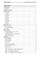
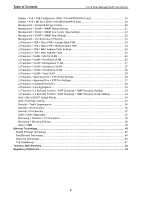
D-Link Smart Managed Switch User Manual Table of Contents Table of Contents ...i About This Guide ...1 Terms/Usage...1 Copyright and Trademarks ...1 1 Product Introduction ...2 DGS-1100-05V2...2 Front Panel ...2 Rear Panel...3 DGS-1100-05PDV2...3 Front Panel ...3 Rear Panel...4 DGS-1100-08V2 - D-Link DGS-1100-05V2 | User Manual 1.00 WW - Page 3
of Contents D-Link Smart Managed Switch User Manual System > PoE > PoE Configuration (DGS-1100-05PDV2/08PV2 only 18 System > PoE > PD Alive (DGS-1100-05PDV2/08PV2 > EEE ...39 Ethernet Technology ...40 Gigabit Ethernet Technology ...40 Fast Ethernet Technology ...40 Switching Technology ...40 PoE - D-Link DGS-1100-05V2 | User Manual 1.00 WW - Page 4
About This Guide D-Link Smart Managed Switch User Manual About This Guide This guide provides step-by-step instructions on how install the D-Link DGS-110005V2/05PDV2/08V2/08PV2 Smart Managed Switches, how to use the Web Utility, and how to perform webbased management functions. Note: The model you - D-Link DGS-1100-05V2 | User Manual 1.00 WW - Page 5
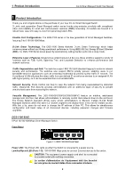
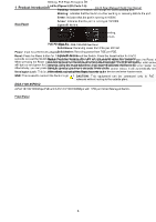
and firmware upgrades. DGS-1100-05V2 5-Port 10/100/1000Mbps Smart Managed Switch. Front Panel Figure 1.1 - DGS-1100-05V2 Front Panel Power LED: The Power LED lights up when the Switch is connected to a power source. Link/Act/Speed LED (Ports 1-5): 10/100/1000 Mbps ports to connect Ethernet devices - D-Link DGS-1100-05V2 | User Manual 1.00 WW - Page 6
Introduction Rear Panel D-Link Smart Managed Switch User Manual Figure 1.2 - DGS-1100-05V2 Rear Panel Power: Input for a 5V/1A AC adapter. Reset: Press the Reset button for 1 to 5 seconds to reboot the Switch. Press the Reset button for 6 to10 seconds to reset the Switch back to the default - D-Link DGS-1100-05V2 | User Manual 1.00 WW - Page 7
3af for DGS-1100-05PDV2. DGS-1100-08V2 8-Port 10/100/1000Mbps Smart Managed Switch. Front Panel Figure 1.5 - DGS-1100-08V2 Front Panel Power LED: The Power LED lights up when the Switch is connected to a power source. Link/Act/Speed LED (Ports 1-8): 10/100/1000 Mbps ports to connect Ethernet devices - D-Link DGS-1100-05V2 | User Manual 1.00 WW - Page 8
mode. Kensington Lock: This is used to attach a physical Kensington security lock. GND: This is used to connect the Switch to ground. DGS-1100-08PV2 8-Port 10/100/1000Mbps PoE Smart Managed Switch. Front Panel Figure 1.7 - DGS-1100-08PV2 Front Panel Power LED: The Power LED lights up when the - D-Link DGS-1100-05V2 | User Manual 1.00 WW - Page 9
to ground. NOTE: The power budget is 64 Watts for DGS-1100-08P. LED Indicators The Switches feature LED indicators for Power and Link/Act for each port. The following shows the LED indicators for the DGS-1100-05V2/05PDV2/08V2/08PV2 switches along with an explanation of each indicator. Location Per - D-Link DGS-1100-05V2 | User Manual 1.00 WW - Page 10
1 Product Introduction D-Link Smart Managed Switch User Manual LED Per PoE Port PoE Status LED Per PD Port (DGS-1100- PD Status 05PDV2 only) Solid Amber Indicates there is a 10/100 Mbps connection on this port. Blinking Amber Indicates data is being processed on this - D-Link DGS-1100-05V2 | User Manual 1.00 WW - Page 11
DGS-1100-05V2/05PDV2/08V2/08PV2 Smart Managed Switch One AC external power adapter Four rubber feet Wall-mount kit Quick Installation Guide CD (User manual Switch can be mounted on a wall. Two mounting slots are provided on the bottom of the switch for this purpose. Please refer to the instructions - D-Link DGS-1100-05V2 | User Manual 1.00 WW - Page 12
Hardware Installation D-Link Smart Managed Switch User Manual Step 2. Hook the mounting keyholes on the back of the Switch onto the screws to secure the device to the wall. Figure 2.2 - Wall mount installation Metal screw (M7 type; Length 16 mm, Number of screws *2) for DGS-1100-05V2/05PDV2/08V2 - D-Link DGS-1100-05V2 | User Manual 1.00 WW - Page 13
multiple D-Link Managed Switches. Please refer to the following installation instructions for the Web interface and the D-Link Network front panel of the Switch and connect the other end of Ethernet cable to the Ethernet port on the PC. Figure 3.1 - Connected Ethernet cable Accessing the Web- - D-Link DGS-1100-05V2 | User Manual 1.00 WW - Page 14
Started D-Link Smart Managed Switch User Manual Figure 3.2 -Enter the IP address 10.90.90.90 in the web browser NOTE: The Switch's factory default for detailed instructions. D-Link Network Assistant (DNA) D-Link Network Assistant (DNA) is a program that is used to discover switches which are in - D-Link DGS-1100-05V2 | User Manual 1.00 WW - Page 15
Configuration D-Link Smart Managed Switch User Manual 4 Configuration The features and functions of the D-Link Smart Managed Switch can be provides a quick and convenient way for accessing essential functions such as firmware upgrades and basic settings. Clicking on a section or subsection in the - D-Link DGS-1100-05V2 | User Manual 1.00 WW - Page 16
4 Configuration D-Link Smart Managed Switch User Manual Tool Bar > Save Menu The Save Menu provides basic functions such as Reset, Reset System, Reboot Device, Configuration Backup and Restore, Firmware Backup and Upgrade. Figure 4.4 - Tool Menu Reboot System This option provides a safe way - D-Link DGS-1100-05V2 | User Manual 1.00 WW - Page 17
D-Link Support Site will lead you to the D-Link website where you can find online resources such as updated firmware images; User Guide can offer an immediate reference for the feature definition or configuration guide. Figure 4.10 - Online Help Function Tree All configuration options of the switch - D-Link DGS-1100-05V2 | User Manual 1.00 WW - Page 18
4 Configuration D-Link Smart Managed Switch User Manual Figure 4.11 -Function Tree Device Information The Device Information provides an overview of the Switch, including essential information such as firmware and hardware information, and IP address. Figure 4.12 - Device Information System > - D-Link DGS-1100-05V2 | User Manual 1.00 WW - Page 19
4 Configuration D-Link Smart Managed Switch User Manual System Location Specify the system location of the Switch. System Contact Specify the system contact of the Switch. Web Session Timeout (60-36000) The Web Session Timeout controls the idle time-out period for security purposes, when - D-Link DGS-1100-05V2 | User Manual 1.00 WW - Page 20
Link Smart Managed Switch User Manual Ethernet frame size of 1536 bytes) of up to 9216 bytes (tagged). This function is disabled by default. Select Enabled then click Apply to turn on the jumbo frame support. Figure 4.16 - System > Port Configuration > Jumbo Frame System > PoE > PoE System (DGS-1100 - D-Link DGS-1100-05V2 | User Manual 1.00 WW - Page 21
Displays the percentage of system power supplied of the switch. Table 4.4 Click Apply to make the configurations take effect. System > PoE > PoE Configuration (DGS-1100-05PDV2/08PV2 only) The DGS-1100-05PDV2/08PV2 support Power over Ethernet (PoE) as defined by the IEEE specification. The PoE - D-Link DGS-1100-05V2 | User Manual 1.00 WW - Page 22
4 Configuration D-Link Smart Managed Switch User Manual 0 Default 1 Optional 2 Optional 3 Optional 4 This feature available in DGS-1100-08P only.) Legacy Support Specify to enable or disable detecting legacy PDs signal Power Limit This function allows you to manually set the port power - D-Link DGS-1100-05V2 | User Manual 1.00 WW - Page 23
4 Configuration D-Link Smart Managed Switch User Manual Click Apply to make the configurations take PD is still not powering on, please contact the vendor of your device for support. System > PoE > PD Alive (DGS-1100-05PDV2/08PV2 only) PD Alive function is a mechanism to detect PD host periodically - D-Link DGS-1100-05V2 | User Manual 1.00 WW - Page 24
Link Smart Managed Switch User Manual The fields that can be configured for Password Access Control are described below: Item Description Old Password Enter the old password of the Switch. New Password Enter the new password of the Switch and detect potential problems in the Switch or LAN. - D-Link DGS-1100-05V2 | User Manual 1.00 WW - Page 25
4 Configuration D-Link Smart Managed Switch User Manual Warmstart Check this feature to have client devices string is used like a password to give remote SNMP managers access to MIB objects in the Switch's SNMP agent. Table 4.9 Click Apply to create a new SNMP community. Management > SNMP > - D-Link DGS-1100-05V2 | User Manual 1.00 WW - Page 26
4 Configuration D-Link Smart Managed Switch User Manual Community String Specify the community string for the management host. Table 4.10 Click Apply to make the configurations take effect. Management > D-Link Discovery Protocol For devices that support the D-Link Discovery Protocol (DDP), this - D-Link DGS-1100-05V2 | User Manual 1.00 WW - Page 27
4 Configuration D-Link Smart Managed Switch User Manual L2 Features > FDB > Static FDB > Multicast Static FDB The Multicast Static FDB page allows user to view and configure the static multicast forwarding settings on the Switch. Figure 4.26 - L2 Features > FDB > Static FDB > Multicast Static FDB - D-Link DGS-1100-05V2 | User Manual 1.00 WW - Page 28
4 Configuration D-Link Smart Managed Switch User Manual L2 Features > FDB > MAC Address Table The MAC Address Table page allows user to view the entries listed in the MAC address table. Figure 4.28 - - D-Link DGS-1100-05V2 | User Manual 1.00 WW - Page 29
4 Configuration D-Link Smart Managed Switch User Manual The fields that can be configured for 802.1Q VLAN are described below: Item Description VID Enter the VID to be created. VLAN Name Enter - D-Link DGS-1100-05V2 | User Manual 1.00 WW - Page 30
4 Configuration D-Link Smart Managed Switch User Manual Figure 4.33 - L2 Features > VLAN > Port-Based VLAN VLAN The 802.1Q Management VLAN setting allows user to transfer management authority of the switch from the default VLAN to another VLAN. This allows for more flexible network management. By - D-Link DGS-1100-05V2 | User Manual 1.00 WW - Page 31
4 Configuration D-Link Smart Managed Switch User Manual Asymmetric VLAN State Specify to enable or disable the Asymmetric VLAN of the Switch. The default value is disabled. Table 4.18 Click Apply to make the configurations take effect. L2 Features > VLAN > Surveillance VLAN Surveillance VLAN is - D-Link DGS-1100-05V2 | User Manual 1.00 WW - Page 32
D-Link Smart Managed Switch User Manual User-defined MAC Settings Component Type Surveillance VLAN will automatically detect D-Link . Usually, VMS and VMS Clients are necessary components for an IP surveillance service. Description MAC-Address Enter a description for the component. Enter a MAC - D-Link DGS-1100-05V2 | User Manual 1.00 WW - Page 33
4 Configuration D-Link Smart Managed Switch User Manual the Voice VLAN rules. Table 4.20 Below is a list to create a new Voice VLAN. L2 Features > Spanning Tree > STP Global Settings The Switch implements two versions of the Spanning Tree Protocol: Rapid Spanning Tree Protocol (RSTP) as defined - D-Link DGS-1100-05V2 | User Manual 1.00 WW - Page 34
4 Configuration D-Link Smart Managed Switch User Manual and STP. STP Traps STP New Root Trap Select to enable or disable the STP new root trap option. STP Topology Change Select to enable - D-Link DGS-1100-05V2 | User Manual 1.00 WW - Page 35
4 Configuration D-Link Smart Managed Switch User Manual change to the forwarding state. In the Edge mode, the port will directly change to the spanning-tree forwarding state when a link-up occurs without waiting for the forward-time delay. If the interface receives a BPDU later, its operation - D-Link DGS-1100-05V2 | User Manual 1.00 WW - Page 36
configurations take effect. Click Delete to remove the Link Aggregation group. NOTE: Maximum number of ports in a Link Aggregation group is 4. DGS-1100-05V2/05PDV2 only supports 1 Link Aggregation group, and DGS1100-08V2/08PV2 supports up to 2 Link Aggregation groups. NOTE: Each combined port must - D-Link DGS-1100-05V2 | User Manual 1.00 WW - Page 37
Link Smart Managed Switch User Manual Figure 4.42 - L2 Features > L2 Multicast Control > IGMP Snooping > IGMP Snooping Settings The fields that can be configured for are described below: Item Description IGMP Snooping Specify to enable or disable the IGMP Snooping function of the Switch Service - D-Link DGS-1100-05V2 | User Manual 1.00 WW - Page 38
configured are described below: Item Description Global Settings Select QoS mode D-Link Smart Managed Switch allows the user to prioritize the traffic based on the 802.1p priority in the VLAN tag or the DSCP (Differentiated Services Code Point) priority in the IP header. Only one mechanism is - D-Link DGS-1100-05V2 | User Manual 1.00 WW - Page 39
4 Configuration D-Link Smart Managed Switch User Manual The fields that can be configured for Port Rate Limiting to distribute traffic flow from a single port to a group of ports on a single Switch. This method of segmenting the flow of traffic is similar to using VLANs to limit traffic - D-Link DGS-1100-05V2 | User Manual 1.00 WW - Page 40
4 Configuration D-Link Smart Managed Switch User Manual Storm Control Status Storm Control Threshold (8- > Cable Diagnostics The Cable Diagnostics is designed primarily for administrators and customer service representatives to quickly examine the quality of copper cables, recognize the cable - D-Link DGS-1100-05V2 | User Manual 1.00 WW - Page 41
4 Configuration D-Link Smart Managed Switch User Manual Select a port and then click the Test Now button to . Short in Cable means there is an unintended connection between two or more conductors in the Ethernet cable. Open in Cable means the wires of RJ45 cable may be broken or the other - D-Link DGS-1100-05V2 | User Manual 1.00 WW - Page 42
D-Link Smart Managed Switch User Manual Figure 4.52 - Monitoring > Mirroring Settings The fields that can be configured for Mirroring Settings are described below: Item Description Mirroring Settings Destination Frame Type Specify to enable or disable the mirroring function of the Switch - D-Link DGS-1100-05V2 | User Manual 1.00 WW - Page 43
Ethernet Technology D-Link Smart Managed Switch User Manual Ethernet Technology This chapter will describe the features of the D-Link Smart Managed Switch and provide some background information about Ethernet/Fast Ethernet/Gigabit Ethernet switching technology. Gigabit Ethernet Technology Gigabit - D-Link DGS-1100-05V2 | User Manual 1.00 WW - Page 44
Ethernet Technology D-Link Smart Managed Switch User Manual PoE Passthrough The DGS-1100-05PDV2 is a PoE passthrough switch that is powered through a Powered Device (PD) port (Port 5) and can also provide PoE power (Port 1~2) to connected devices. This means that power cords will - D-Link DGS-1100-05V2 | User Manual 1.00 WW - Page 45
Technical Specifications D-Link Smart Managed Switch User Manual Technical Specifications Key Components / Performance Switching Capacity DGS-1100-05V2/05PDV2: 10 Gbps DGS-1100-08V2/08PV2: 16 Gbps Max. Forwarding Rate DGS-1100-05V2/05PDV2: 7.4 Mpps DGS-1100-08V2/08PV2: 11.9 Mpps Forwarding - D-Link DGS-1100-05V2 | User Manual 1.00 WW - Page 46
Technical Specifications D-Link Smart Managed Switch User Manual Operation Temperature Storage Temperature Operation Humidity Storage Humidity EMI Certifications Safety Certifications 0 ~ 40 °C - 40 ~ 70 °C 0%~90% RH 0%~95% RH CE, FCC, ITE, RCM, VCCI, BSMI cUL, CB, BSMI 43 - D-Link DGS-1100-05V2 | User Manual 1.00 WW - Page 47
Link Smart Managed Switch User Manual Regulatory Statements CE Mark Warning: This is a Class B product. In a domestic environment, this product may cause radio interference, in which case the user may be required to take adequate measures. Power Usage (for DGS-1100 with the instructions, may cause - D-Link DGS-1100-05V2 | User Manual 1.00 WW - Page 48
Regulatory Statements D-Link Smart Managed Switch User Manual The following general safety guidelines are provided to help ensure your own personal safety and protect your product from potential damage. Remember to consult the product user instructions for more details. • Static electricity can be - D-Link DGS-1100-05V2 | User Manual 1.00 WW - Page 49
Regulatory Statements D-Link Smart Managed Switch User Manual • La electricidad estática puede resultar nociva para Para algunos productos con batería reemplazable por el usuario, lea y siga las instrucciones del manual de usuario. • No derrame comida o líquidos sobre el producto y nunca deje que - D-Link DGS-1100-05V2 | User Manual 1.00 WW - Page 50
Regulatory Statements D-Link Smart Managed Switch User Manual DISPOSING AND RECYCLING YOUR PRODUCT ENGLISH using recyclable, low toxic materials in both products and packaging. D-Link recommends that you always switch off or unplug your D-Link products when they are not in use. By doing so you - D-Link DGS-1100-05V2 | User Manual 1.00 WW - Page 51
Regulatory Statements D-Link Smart Managed Switch User Manual FRANÇAIS FR Ce symbole apposé sur le aidez à préserver l'environnement et à protéger la santé de l'homme. D-Link et l'environnement Chez D-Link, nous sommes conscients de l'impact de nos opérations et produits sur l'environnement et - D-Link DGS-1100-05V2 | User Manual 1.00 WW - Page 52
Regulatory Statements D-Link Smart Managed Switch User Manual D-Link cerca da sempre di ridurre l'impatto ambientale dei propri stabilimenti e dei propri prodotti. Allo scopo di ridurre al minimo tale impatto, D-Link progetta e realizza i propri prodotti in modo che rispettino il più possibile l' - D-Link DGS-1100-05V2 | User Manual 1.00 WW - Page 53
Regulatory Statements D-Link Smart Managed Switch User Manual ČESKY CZ Tento symbol na výrobku nebo Recyklací výrobku i obalu pomáháte chránit životní prostředí i lidské zdraví. D-Link a životní prostředí Ve společnosti D-Link jsme si vědomi vlivu našich provozů a výrobků na životní prostředí a - D-Link DGS-1100-05V2 | User Manual 1.00 WW - Page 54
Regulatory Statements D-Link Smart Managed Switch User Manual NORSK NO Dette symbolet på produktet eller på denne måde bidrager du til at beskytte miljøet og den menneskelige sundhed. D-Link og miljøet Hos D-Link forstår vi og bestræber os på at reducere enhver indvirkning, som vores aktiviteter - D-Link DGS-1100-05V2 | User Manual 1.00 WW - Page 55
D-Link Smart Managed Switch User Manual D-Link ja ympäristö D-Link ymmärtää ympäristönsuojelun tärkeyden ja on sitoutunut vähentämään tuotteistaan ja niiden valmistuksesta ympäristölle mahdollisesti aiheutuvia haittavaikutuksia. Nämä negatiiviset vaikutukset minimoidakseen D-Link suunnittelee - D-Link DGS-1100-05V2 | User Manual 1.00 WW - Page 56
-
 1
1 -
 2
2 -
 3
3 -
 4
4 -
 5
5 -
 6
6 -
 7
7 -
8
-
9
-
10
-
11
-
12
-
13
-
14
-
15
-
16
-
17
-
18
-
19
-
20
-
21
-
22
-
23
-
24
-
25
-
26
-
27
-
28
-
29
-
30
-
31
-
32
-
33
-
34
-
35
-
36
-
37
-
38
-
39
-
40
-
41
-
42
-
43
-
44
-
45
-
46
-
47
-
48
-
49
-
50
-
51
-
52
-
53
-
54
-
55
-
56
 |
 |
